

BMR Suspension TCC019 User Manual
TORQUE ARM RELOCATION CROSSMEMBERS
1982-1992 F-Body
Part Numbers: TCC015, TCC016, TCC017, TCC018, TCC019
Installation Notes:
• These instructions do not cover the transmission conversion process, only the specifics associated with our tubular cross-
members. Due to vehicle year variances as well as various exhaust and driveshaft configurations, this is not a step-by-step
installation guide.
• BMR Torque Arm Relocation Crossmembers are designed to work with BMR torque arms only. They are not compatible
with OE or other aftermarket torque arms.
Installation:
• Verify that you have the correct cross-member for your application before pro ceeding with the installation.
TCC015 – T5 manual TCC016 – M6 manual TCC017 – TH700R4 TCC018 – PG / TH350 TCC019 – TH400
• Torque Arm attachment:
1. With the transmission installed, mount the BMR crossmember to the frame using the
factory hardware. When using part number TCC015, replace the factory transmission
mount with the supplied polyurethane mount.
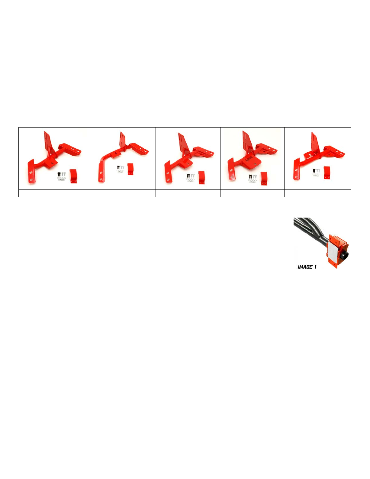
2. Position the supplied saddle over the torque arm bushing and insert the supplied alu minum
spacer plate behind the bushing as shown in Image 1 to the right.
3. The transmission being installed will dictate the torque arm mounting location on the
crossmember. IMPORTANT: For all transmissions except the T56 manual, the torque
arm mounts to the drivers side of the upright mounting plate, see Image below. When
installing a T56 manual transmission, the torque arm mounts to the passenger side of the
upright bracket. When bolting the saddle to the crossmember, the flat carriage bolts are used in the upper holes due
to minimal access room. See additional installation notes below if you are having clearance issues when mounting
the torque arm to the crossmember.
• On certain model years, the fuel lines have a large retainer mounted midway up the driveshaft tunnel. To properly position
the torque arm , it is necessary to remove this bracket.
• To provide additional clearance for large diameter driveshafts, the BMR torque arm crossmember has been designed to
position the torque arm away from the driveshaft. When using the upper mounting locations of the crossmember, it will be
necessary to clearance the driveshaft tunnel for torque arm clearance.
Adjustment:
To approximate the OE torque arm position, mount the torque arm in the middle mounting holes. Raising or lowering this mounting
location of the front torque arm mount changes the “instant center” height in the vehicle. There are too many variables (spring rate,
shock valving, ride height, front-to-rear weight bias, etc.) to recommend an ideal setting that works for every application so it is best to
start in the middle and take the car to the track for tuning. Ideal launch characteristics will produce minimal suspension squat. As a
general rule of thumb if the rear of the car squats, raise the torque arm mounting point; if the rear lifts too much (body separation),
lower the torque arm mounting point. Additionally take note that instant center can be moved front to rear by installing a set of rear
control arm relocation brackets. This effectively alters the imaginary intersect point of the torque arm and control arms. By
combining these few parts, it allows the user to have complete control of the vehicles instant center. For additional chassis tuning
tips, contact our Tech department at Tech@bmrfabrication.com or call 813-986-9302.
This product is an aftermarket accessory and not designed by the vehicles manufacturer for use on this vehicle. As such, Buyer
assumes all risk of any damage caused to the vehicle or person during installation or use of this product.
WWW.BMRFABRICATION.COM
 Loading...