

BMR Suspension TAS010 User Manual
TORQUE ARM CONVERSION INSTALLATION INSTRUCTIONS
TAS010 - 1968-1974 Nova 10 BOLT
Please take note before proceeding with this installation:
• This product may interfere with certain exhaust kits. Exhaust crossovers are not
compatible with this torque arm suspension. In some circumstances, it may be necessary
to fabricate a custom exhaust for proper clearance.
• While not necessary, a heavy duty cast aluminum differential cover is recommended with
this kit. These covers are more structural in nature than the stamped steel OE unit and
will distribute the load across the differential, further strengthening the assembly.
TOOLS REQUIRED:
3/8” and ½” drive ratchets
½”, 5/8” deep, 9/16”, ¾” deep, 15/16” and 1-1/8” sockets
Pry-bar
3/8” Allen wrench
ADDITIONAL ITEMS REQUIRED:
RTV gasket silicone
Gear oil
CROSS-MEMBER
INSTALLATION:
1) Lift the vehicle and support
with stands under the rocker
panel pinch seams (Do not
place stands under the
subframe).
2) Remove the exhaust system.
3) Using a 15/16” socket,
remove the rear two body
mount bolts.
4) Remove the OE rubber body
mount bushings. They are
composed of an upper and
lower bushing that
“sandwich” the subframe
together in the middle. NOTE: a pry-bar may be necessary to get the subframe low
enough to remove these bushings.
5) Once the OE bushings have been removed, inspect the subframe for rust damage. This is
a common area susceptible to rust and if the mounting point is compromised, it needs to
be repaired before proceeding with the installation.
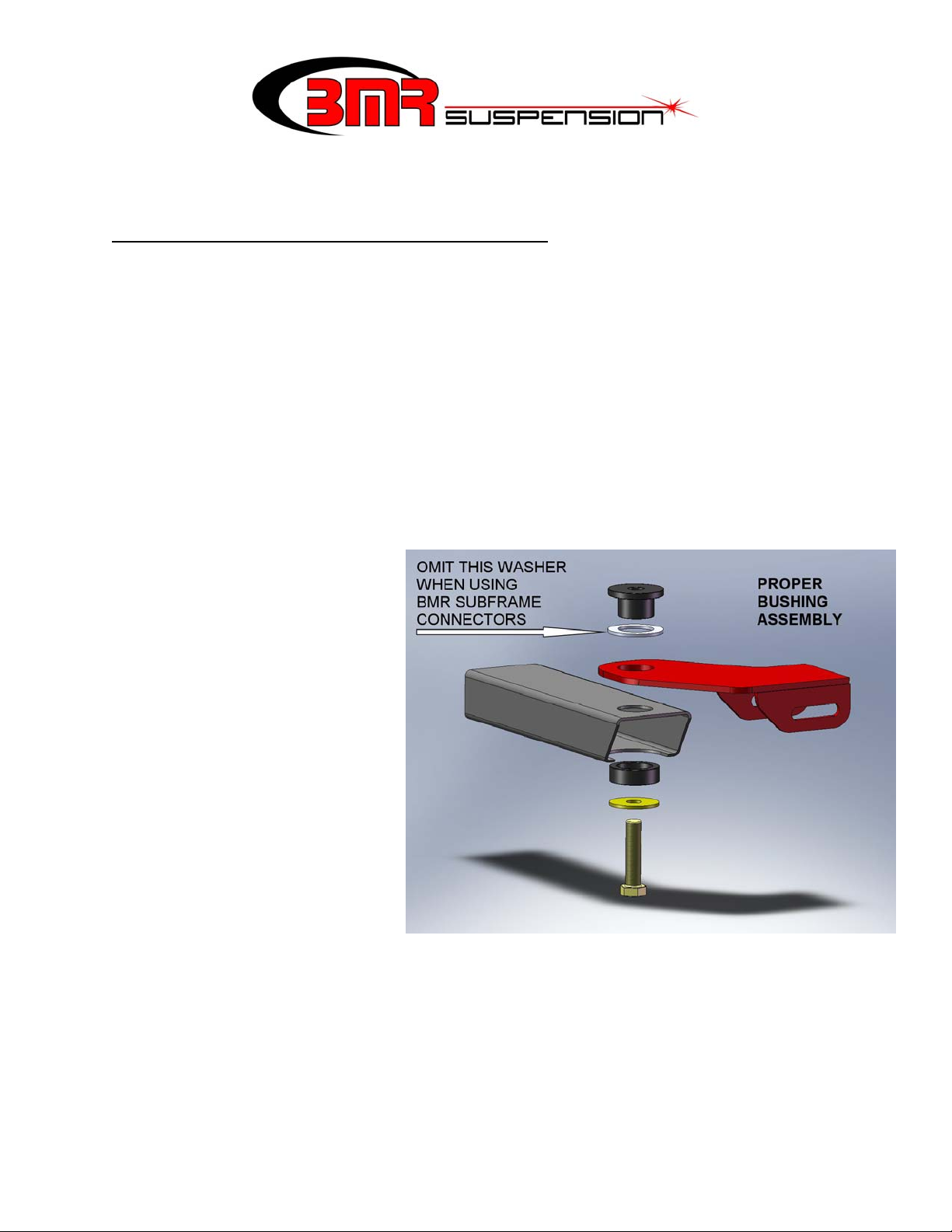
6) Begin with the driver’s side. Assemble the driver’s side frame mount, billet body mounts
and washer (if necessary) as shown in the image above. If you are using a subframe
connector that mounts around the body bushing, omit the supplied aluminum spacer
washer shown in Image 1 above.
1
CROSS-MEMBER INSTALLATION (Cont.)
7) Thread the supplied 5/8” bolt, washer and lock washer into the body and snug the bolt
just enough to allow the frame bracket to rotate around the axis of the bushing.
8) Repeat steps 4-7 for the passenger side. At this stage both mounts should be installed and
you can mount the cross-member. Lift the cross-member into place and insert the
supplied ½” x 4.5” bolts, (8) stainless washers, and nuts.
9) Tighten the body mount bolts to 150 ft/lbs.
10) Center the cross-member to the driveshaft then tighten the (4) cross-member bolts.
TORQUE ARM INSTALLATION INSTRUCTIONS:
1) Remove the differential drain plug or loosen the cover bolts to drain the gear oil from the
differential.
2) If it was not necessary to remove the cover previously, remove the 12 bolts from the
differential cover and remove the cover.
3) Using a gasket scraper, remove all
gasket material from the cover and the
differential.
4) Thread the four supplied 5/16” studs into
the differential at the four corners. All
studs should bottom out and should
thread in to the same depth. If not, run a
5/16-18 bottoming tap through the holes
in the differential.
5) Apply a thin bead of RTV Black or Grey
gasket silicone onto the differential
gasket mating surface. Install one of the
supplied gaskets.
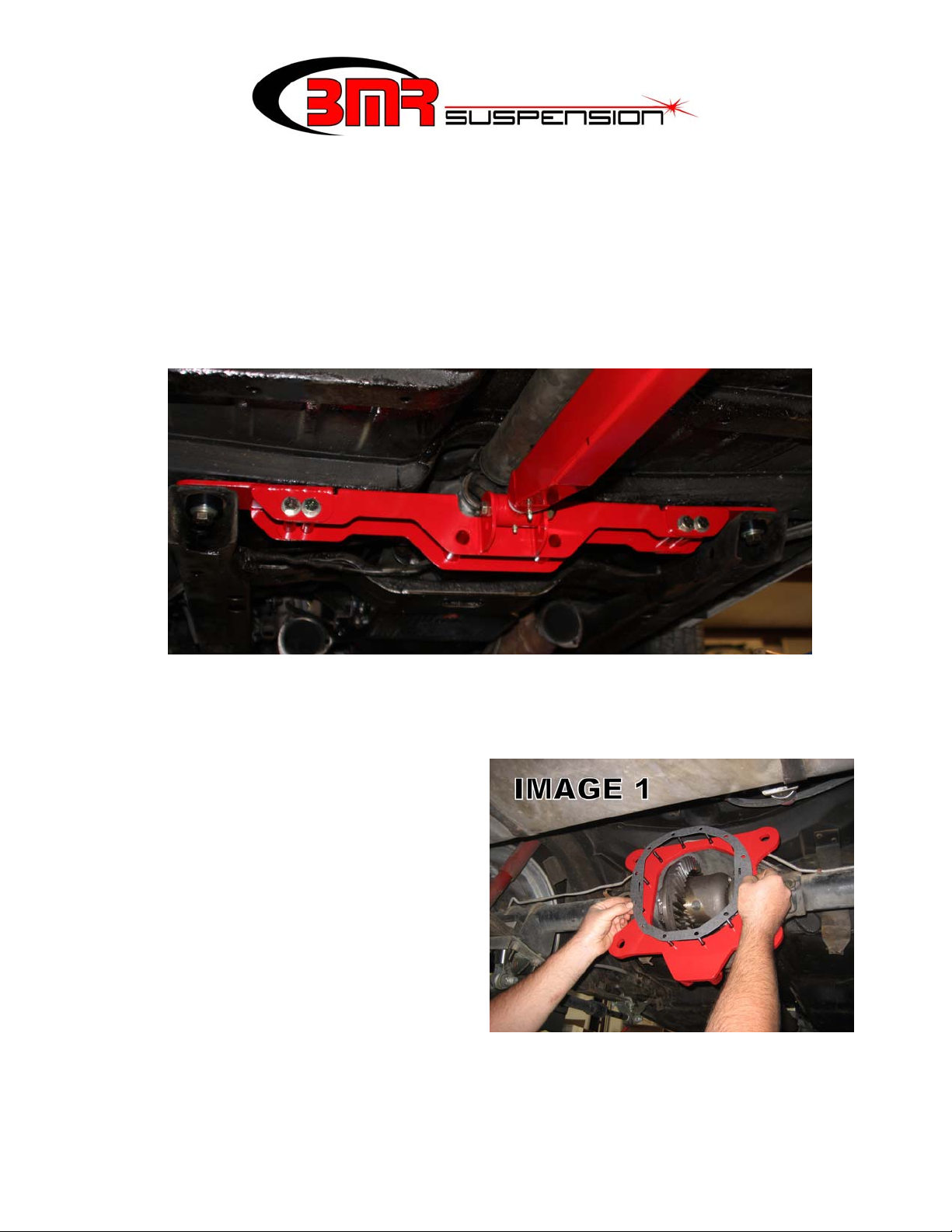
6) Apply another thin bead of RTV on the exposed gasket surface. Position the BMR torque
arm mounting plate onto the rear end with the torque arm mounting points facing forward
as in Image 1 above.
2
TORQUE ARM INSTALLATION INSTRUCTIONS (Cont.)
7) Apply another thin bead of RTV onto the BMR torque arm mounting plate at the gasket
mating surface then install the other
supplied gasket.
8) Apply another thin bead of RTV onto the
exposed gasket surface then re-install the
differential cover.
9) Place one of the supplied 5/16” washers
and 5/16” poly-lock nuts onto each stud
and then insert the (6) 5/16” bolts and
washers into the remaining holes. Tighten
all twelve in a star shaped pattern. Snug
each one first then torque them to 20-25
ft/lbs.
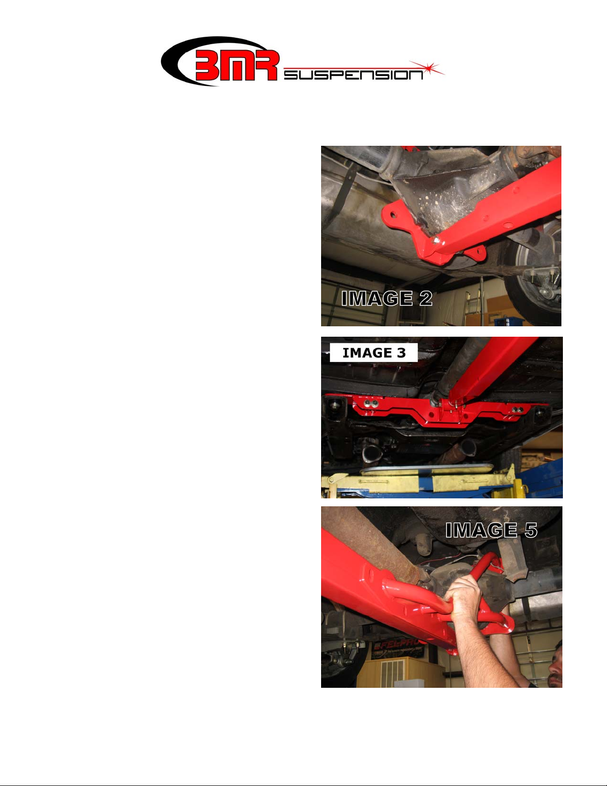
10) Mount the torque arm to the differential
mounting plate using one of the supplied
½” x 3.25” bolts. Place a stainless washer
under the nut and temporarily thread it
finger tight. (See Image 2)
11) Insert the front telescoping bushing into
the torque arm with the grease fitting
pointing downward.
12) Lift the front of the torque arm up until the
bushing hole lines up with the mount on
the torque arm cross-member. Insert the
supplied ½” x 4” bolt, nut and stainless
washer. Tighten to 90 ft/lbs. (Image 3)
13) Using either a 5/8” or ¾” deep socket,
slightly loosen the leaf spring mounts on
the rear end. They should be loose enough
to allow the rear end to rotate slightly.
14) Position one of the support braces up
against the torque arm as shown in Image
5. Place a lock washer over two of the
supplied ¾” x 2” bolts and thread them
into the support brace, through the BMR
differential mounting plate. Leave the
bolts loose.
3
TORQUE ARM INSTALLATION INSTRUCTIONS (Cont.)
15) Repeat step 18 for the other side.
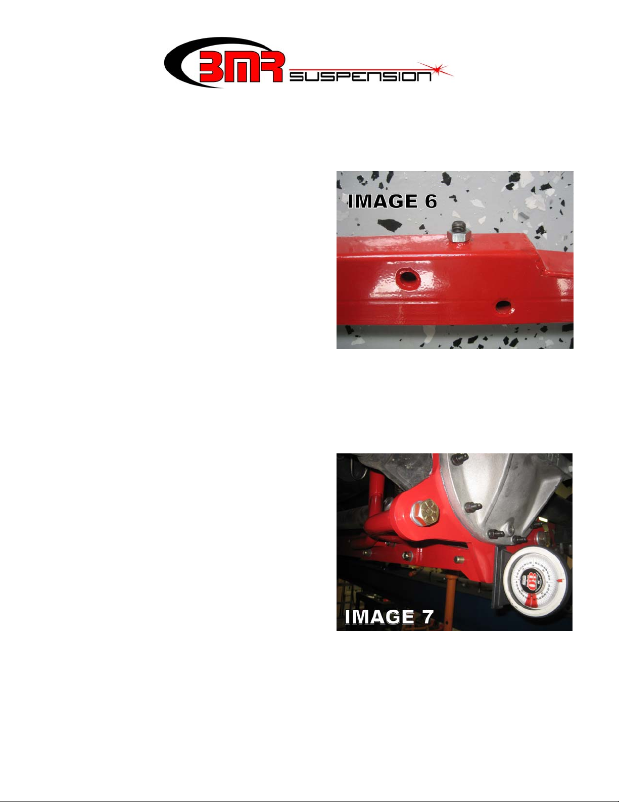
16) Loosen the jack screw from the bottom side of the torque arm using a 3/8” Allen
wrench.(Image 6) Loosen it as far as
possible to provide clearance between the
rear end and the torque arm. This will be
adjusted in a later step.
17) Place washers over the supplied ½” x 3.25”
bolts and insert them into the four holes on
the torque arm. It is typical for these holes
not to align properly and is necessary to use
a pry-bar to pivot the rear end until all four
bolts slide through. NOTE: this step is
somewhat difficult and it may seem that the
parts do not fit together however all
assemblies are pre-fit and tested before
shipping to insure proper fitment.
18) Once all four bolts are through the assembly, place another washer and a nut on each one
and finger-tighten them.
19) Using a 1-1/8” socket, tighten the four ¾” bolts on the rear of the differential mounting
plate to 100 ft/lbs.
20) The following step involves setting the driveline angle. While this process is actually
very simple, it is difficult to explain so we have provided detailed instructions and
examples below. Driveline angle is the difference between the pinion angle and the
driveshaft angle. Zero degrees means there
is no angle and the pinion and driveshaft are
straight as viewed from the side. If the
angle is negative, the driveshaft and the
rear-end will form a “V”. If it is positive,
the driveshaft and rear-end will form an
“upside down ^”. For street driving this
angle should be between 0 and -3 degrees to
promote long u-joint life.
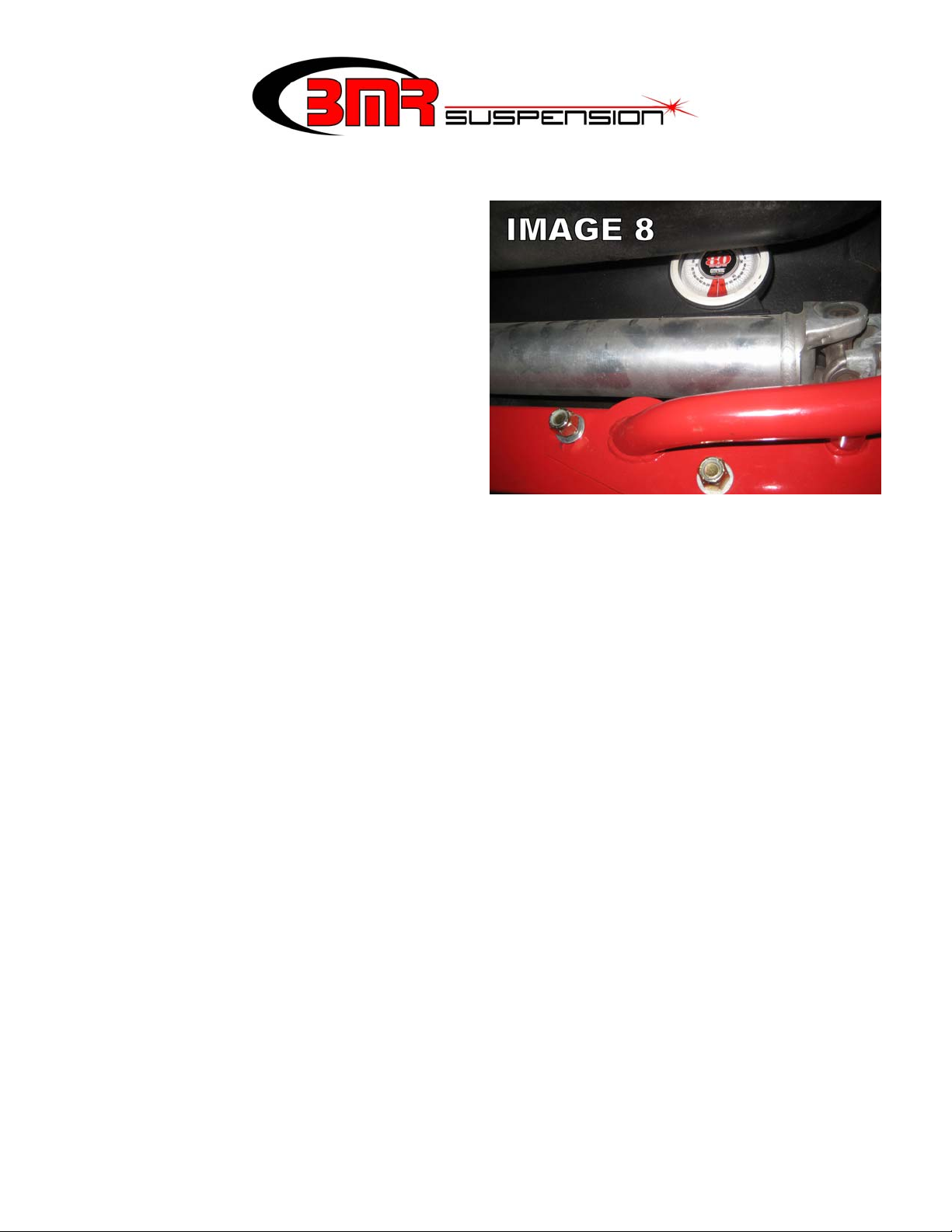
Begin by placing the supplied angle finder
on the rear BMR mounting plate as shown
in Image 7 and record the reading. Take
your reading from the drivers’ side of the
car. Since the rear cover is 90 degrees perpendicular to the pinion, this angle represents
the angle of the pinion gear minus 90 degrees. Now place the angle finder on the
driveshaft (Image 8) and record the reading from the drivers’ side of the car. This angle
represents the driveshaft angle. The goal angle to reach is a 2 degree difference between
the two recorded angles. For example, our test car used for these instructions had the
following readings:
4
TORQUE ARM INSTALLATION INSTRUCTIONS (Cont.)
The rear angle on the differential
mounting plate was 88 degrees. You
need to subtract 90 degrees from this to
get your pinion angle, resulting in -2.
The driveshaft angle just happened to be
at 0 degrees. The difference between
these two angles is -2, right where we
want to be. If your resulting angle is
anywhere between 0 and -3, it is an
acceptable angle. To adjust this angle
you can use the jack screw located at the
back of the torque arm to raise or lower
the pinion simply by turning the screw
(refer back to Image 6). The screw will
turn against the rear end, pushing it upward. If the angle is off excessively, use a pry-bar
to rotate the rear end until the angle is close enough to use the jack screw.
21) Once the driveline angle is set, tighten all 5 cross-bolts to 90 ft/lbs.
22) Make sure the jack screw is touching the differential housing and then tighten the jam-nut
located on the jack screw.
23) Re-tighten the leaf spring bolts.
24) Fill the differential with gear lube.
25) Grease both of the front grease fittings with a silicone or other synthetic based lube.
5
 Loading...