

BMR Suspension TAS005 User Manual
TAS005 TORQUE ARM CONVERSION INSTALLATION INSTRUCTIONS
1970-1981 Camaro and Firebird – Ford 9” rear
Please take note before proceeding with this installation:
• This product may interfere with certain exhaust kits. Exhaust crossovers are not
compatible with this torque arm suspension. In some circumstances, it may be necessary
to fabricate a custom exhaust to insure adequate clearance.
• A service lift, while not necessary, is recommended for this installation.
TOOLS REQUIRED:
3/8” and ½” drive ratchets 9/16”, ¾”, 15/16” wrenches
3/8”, 9/16”, ¾”, 15/16” and 1-1/8” sockets Rubber mallet
Pry-bar Drill
3/8” Allen wrench Step bit or ½” and ¾” drill bits
Jack stands Hydraulic Jack
Grease gun with synthetic lube Torque wrench
Welder (optional) Plumb bob and tape measure
CROSS-MEMBER INSTALLATION:
1) Lift the vehicle and support
with stands under the rocker
panel pinch seams (Do not
place stands under the
subframe).
2) Remove the exhaust system.
3) Using a 15/16” socket,
remove the rear two body
mount bolts.
4) Remove the OE rubber body
mount bushings. They are
composed of an upper and
lower bushing that
“sandwich” the subframe
together in the middle.
NOTE: it may be necessary
to use a pry-bar to lower the
subframe enough to remove
these bushings.
5) Once the OE bushings have been removed, inspect the subframe for rust damage. This is
a common area susceptible to rust and if the mounting point is compromised, it needs to
be repaired before proceeding with the installation.
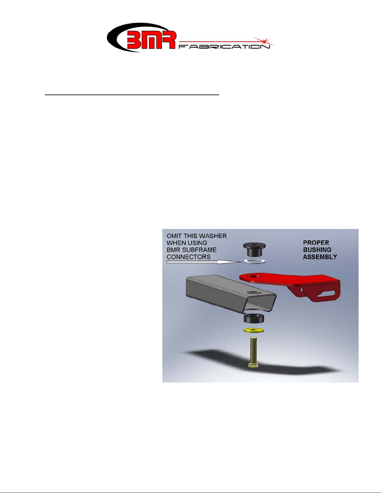
6) Begin with the driver’s side. Assemble the driver’s side frame mount, billet body mounts
and washer (if necessary) as shown in the image above. If you are using BMR subframe
connectors or any subframe connector that mounts around the body bushing, omit the
supplied aluminum spacer washer shown in the above image.
1
CROSS-MEMBER INSTALLATION (Cont.)
7) Thread the supplied bolt into the body and snug the bolt allowing the frame bracket to
rotate around the axis of the bushing.
8) Repeat steps 4-7 for the passenger side. At this stage both mounts should be installed and
you can mount the cross-member. Lift the cross-member into place and insert the
supplied ½” x 4.5” bolts, stainless washers, and nuts.
9) Tighten the body mount bolts to 150 ft/lbs.
10) Center the cross-member to the driveshaft then tighten the (4) cross-member bolts.
TORQUE ARM INSTALLATION:
1. Lift vehicle and support with stands under
the frame, allowing the rear end to hang.
2. Remove the rear wheels/tires.
3. If the vehicle has exhaust installed,
remove it at this time.
4. Remove the rear shocks using a 9/16”
socket.
5. While not necessary, the installation is
simpler if the fuel tank is removed. If you
do not wish to remove the fuel tank, skip
steps 6-8 and proceed to step 9.
6. Drain the tank using a drill pump or
siphon.
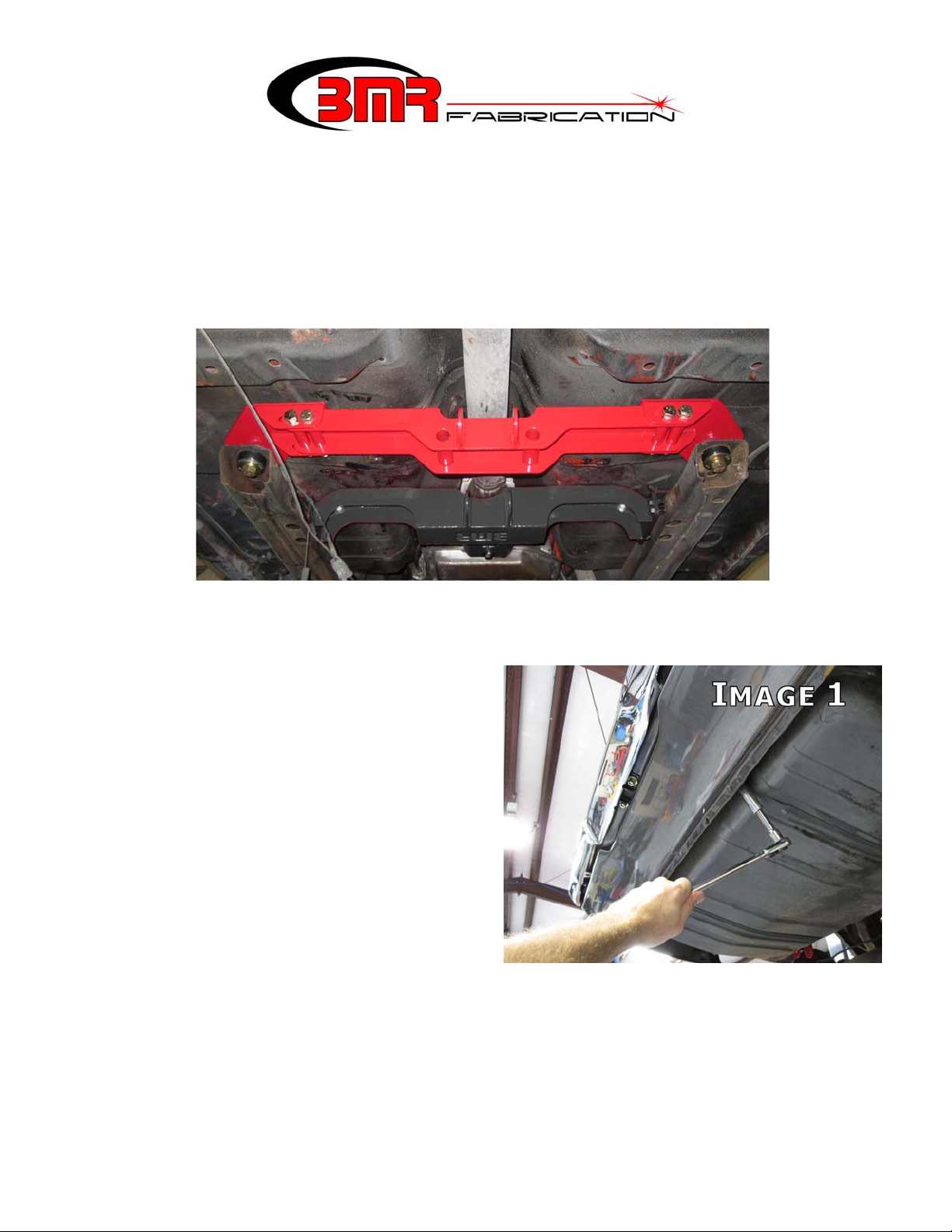
7. Support the tank and then remove the two
mounting nuts using a 9/16” deep socket.
Pull the tank support straps down, allowing the tank to be lowered. (Image 1)
8. Lower the tank far enough to access the fuel lines and electrical connectors. Disconnect
and cap the fuel lines. Lower and remove the fuel tank.
2
(CONTINUED)
9. Support the rear end with jack stands.
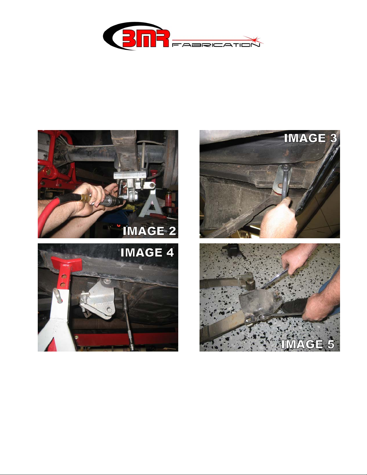
10. Using a 3/4” socket, remove the leaf spring U-bolts on the rear end. (Image 2)
NOTE: the image shown has aftermarket traction bars installed. Leaf spring mounts
may appear slightly different in nature.
11. Using a 5/8” socket, loosen and remove the rear leaf spring shackle bolts. Loosen the
upper shackle bolt at the frame and remove the shackles. (Image 3)
12. Using a 9/16” socket, remove the (3) bolts on the front spring mount of each leaf spring.
(Image 4) NOTE: the image shown had aftermarket traction bars installed. Front leaf
spring eye may appear slightly different in nature.
13. Once all bolts are removed, remove the leaf springs.
14. Remove the rear end and set aside.
15. Loosen the bolts and remove the front spring pockets. (Image 5)
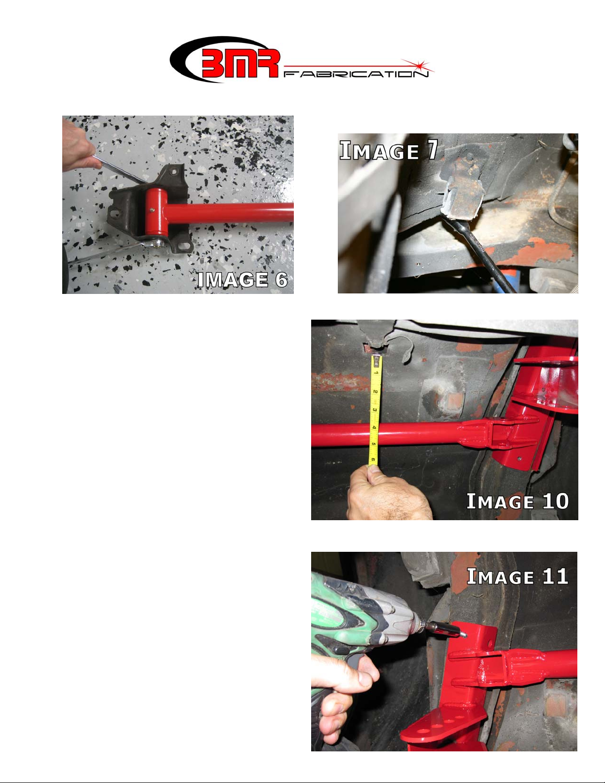
16. Install the BMR trailing arms into the leaf spring pockets as shown using the provided ½”
x 5” bolts. Thread a stainless washer under the nut then tighten to 80 ft/lbs. (Image 6)
17. Re-install the spring pockets with control arms into the body and leave bolts finger tight.
3
(CONTINUED)
18. The next few steps involve installation of the shock cross-member. Begin by removing
the factory muffler hangers located
above the rear end. (Image 7).
19. NOTE: Images 8 and 9 have been
omitted due to updated design.
20. The cross-member can be welded or
bolted into place. Locating the shock
cross-member properly is important and,
while it can be performed by one person,
it is much easier with a helper. Have a
helper hold the shock cross-member up
into place on the frame rails. Slide the
cross-member as far forward as it will
allow.
21. Use the fuel tank strap mounting
positions as a reference point to locate
the cross-member properly front-to-back
and to insure that the cross-member is mounted square in the body. As shown in Image
10, measure the distance from the relief
in the trunk pan to the main cross tube of
the cross-member. Vehicle production
variance prevents a “one measurement
fits all” figure
but the measurements should fall
somewhere between 3-7/8” to 4 1/16” when viewing the tape measure
from directly below. Re-position the
cross-member until the reading from
each strap mount relief is equal and falls
within the range listed above.
4
 Loading...