

TAS004 TORQUE ARM CONVERSION INSTALLATION INSTRUCTIONS
1970-1981 Camaro and Firebird – 12 bolt rear
Please take note before proceeding with this installation:
• This product may interfere with certain exhaust kits. Exhaust crossovers are not
compatible with this torque arm suspension. In some circumstances, it may be necessary
to fabricate a custom exhaust to insure adequate clearance.
• While not necessary, a heavy duty cast aluminum differential cover is recommended with
this kit. Cast covers are more structural in nature than the stamped steel OE unit and
will distribute the load across the differential, further strengthening the assembly.
• A service lift, while not necessary, is recommended for this installation.
TOOLS REQUIRED:
3/8” and ½” drive ratchets 9/16”, ¾”, 15/16” wrenches
3/8”, 9/16”, ¾”, 15/16” and 1-1/8” sockets Rubber mallet
Pry-bar Drill
3/8” Allen wrench Step bit or ½” and ¾” drill bits
Jack stands Hydraulic Jack
Grease gun with synthetic lube Torque wrench
Welder (optional) Plumb bob and tape measure
INSTALLATION:
This installation is the second part of the torque arm conversion process. It is assumed at this
point that the installer has already installed the BMR Torque Arm and Torque Arm crossmember using the appropriate instruction sheets. If you do not have these instruction sheets,
please contact BMR or download them from the BMR website before proceeding with the
following installation instructions.
1. Lift vehicle and support with stands under
the frame, allowing the rear end to hang.
2. Remove the rear wheels/tires.
3. If the vehicle has exhaust installed,
remove it at this time.
4. Remove the rear shocks using a 9/16”
socket.
5. While not necessary, the installation is
simpler if the fuel tank is removed. If you
do not wish to remove the fuel tank, skip
steps 6-8 and proceed to step 9.
6. Drain the tank using a drill pump or
siphon.
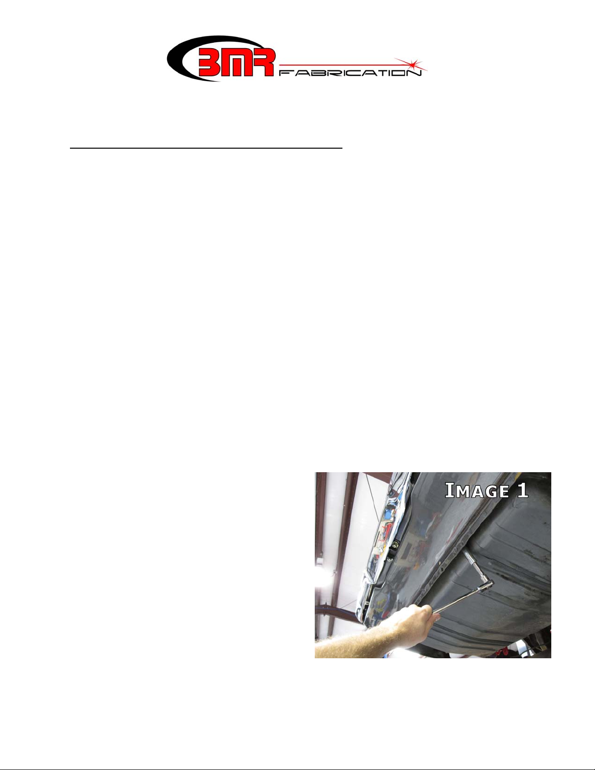
7. Support the tank and then remove the two
mounting nuts using a 9/16” deep socket.
Pull the tank support straps down, allowing the tank to be lowered. (Image 1)
8. Lower the tank far enough to access the fuel lines and electrical connectors. Disconnect
and cap the fuel lines. Lower and remove the fuel tank.
(CONTINUED)
1
9. Support the rear end with jack stands.
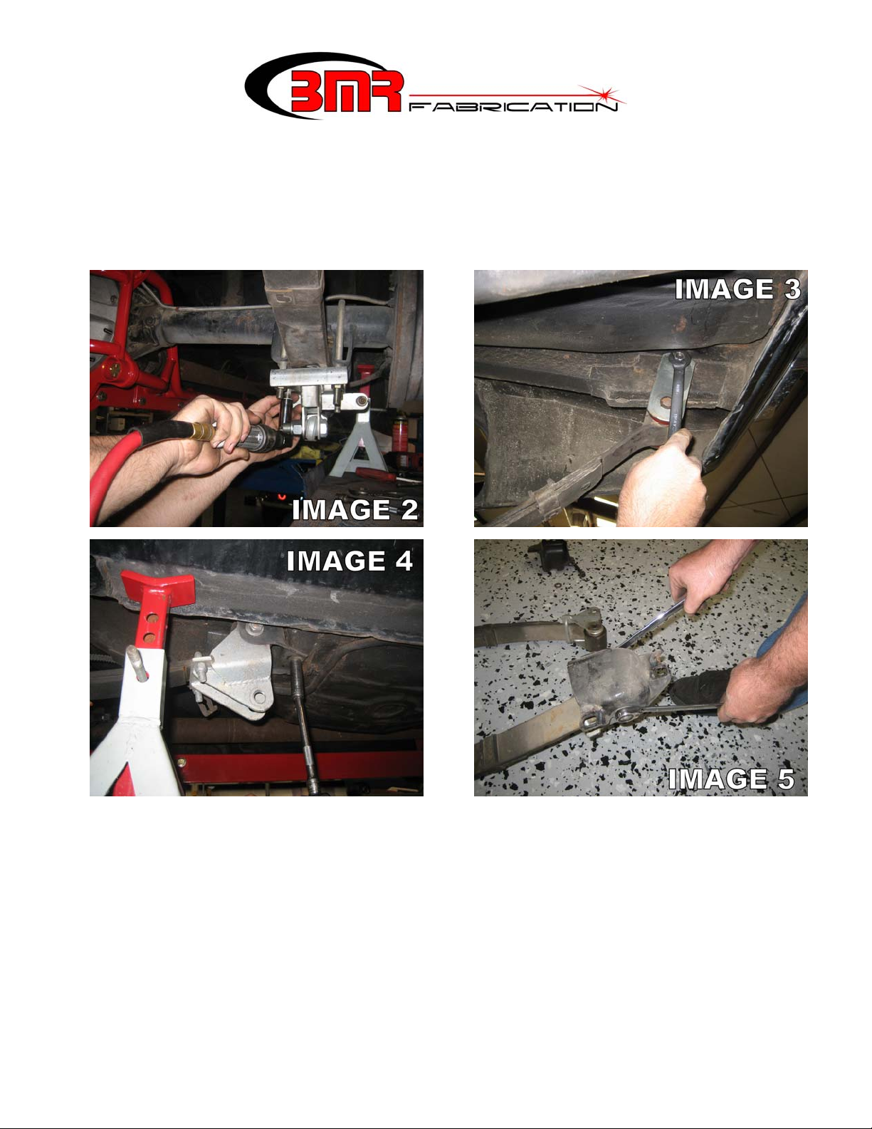
10. Using a 3/4” socket, remove the leaf spring U-bolts on the rear end. (Image 2)
NOTE: the image shown has aftermarket traction bars installed. Leaf spring mounts
may appear slightly different in nature.
11. Using a 5/8” socket, loosen and remove the rear leaf spring shackle bolts. Loosen the
upper shackle bolt at the frame and remove the shackles. (Image 3)
12. Using a 9/16” socket, remove the (3) bolts on the front spring mount of each leaf spring.
(Image 4) NOTE: the image shown had aftermarket traction bars installed. Front leaf
spring eye may appear slightly different in nature.
13. Once all bolts are removed, remove the leaf springs, leaving the rear end in its original
position.
14. Once the leaf springs have been removed, loosen the bolts and remove the front spring
pockets. (Image 5)
15. Install the BMR trailing arms into the leaf spring pockets as shown using the provided ½”
x 5” bolts. Thread a stainless washer under the nut then tighten to 80 ft/lbs. (Image 6)
16. Re-install the spring pockets into the body as shown in Image 7. Leave bolts finger tight.
(CONTINUED)
2
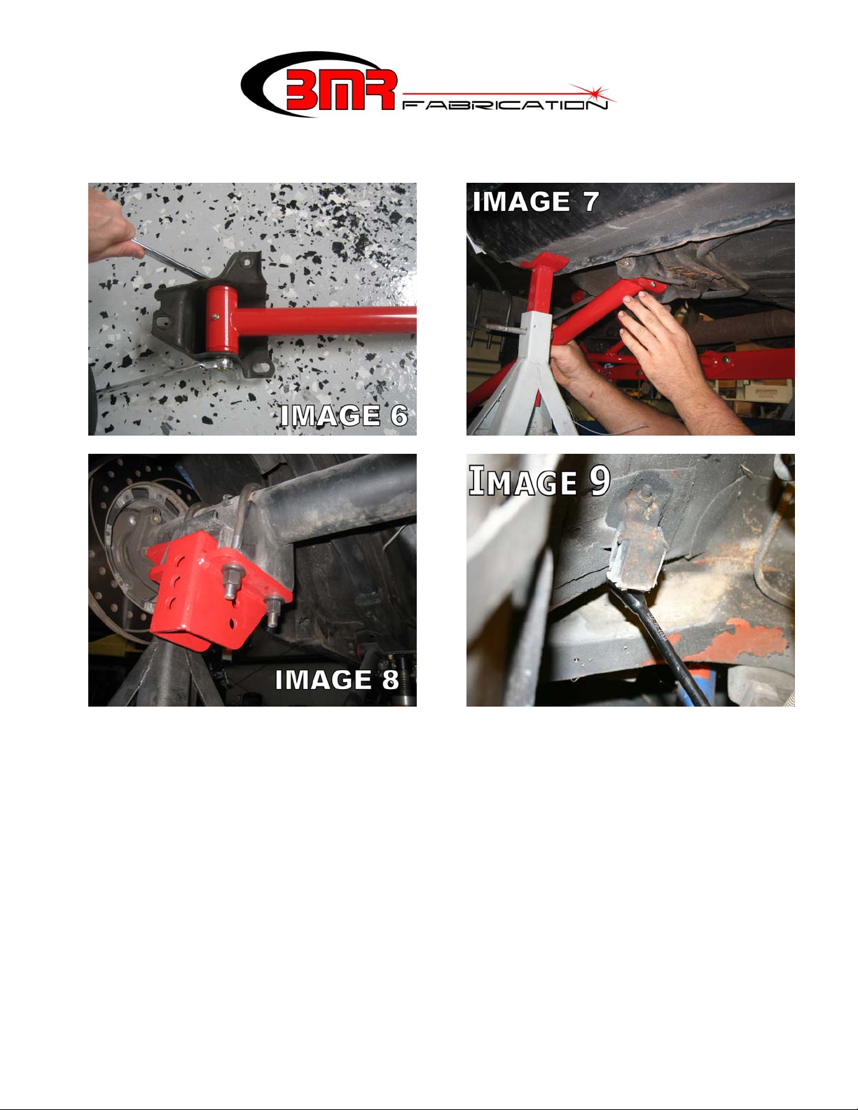
17. Install the BMR control arm mounts onto the axle using the supplied U-bolts. The open
portion of the mount should face forward as shown in Image 8. Tighten nuts to 90 ft/lbs.
18. Lift and insert the other end of the control arm into the axle brackets on the highest
mounting hole and insert the supplied ½” x 3.25” bolts. This connection should be left
loose until a later step. NOTE: it may be necessary to adjust the length of the control
arms to match the holes in the control arm mounts. It may also be necessary to move the
rear end forward or back to line the mounting holes up. If one trailing arm is adjusted,
duplicate this procedure on the other arm and verify that they are equal in length before
proceeding to the next step.
19. The next few steps involve installation of the shock cross-member. Begin by removing
the factory muffler hangers located above the rear end. (Image 9).
20. The cross-member can be welded or bolted into place. Locating the shock cross-member
properly is important and, while it can be performed by one person, it is much easier with
a helper. Have a helper hold the shock cross-member up into place on the frame rails.
Slide the cross-member as far forward as it will allow.
(CONTINUED)
3
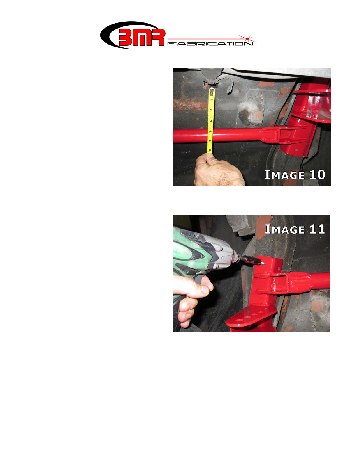
21. Use the fuel tank strap mounting
positions as a reference point to
locate the cross-member properly
front-to-back and to insure that the
cross-member is mounted square in
the body. As shown in Image 10,
measure the distance from the relief
in the trunk pan to the main cross
tube of the cross-member. Vehicle
production variance prevents a “one
measurement fits all” figure
but the measurements should fall
somewhere between 3-7/8” to 4 1/16” when viewing the tape
measure from directly below.
Re-position the cross- member until
the reading from each strap mount relief is equal and falls within the range listed above.
22. Once properly positioned, locate the
provided sheet metal screws in the
hardware pack. As shown in Image
11, screw the cross-member into
each frame rail to hold it into
position for the upcoming steps.
NOTE: the cross-member should
draw up tight against the frame rail.
Any floor pan deformations that
prevent the cross-member from
fitting flush against the frame rail
should be adjusted using a pry-bar
or rubber mallet.
23. At this step the cross-member may be welded to the subframe or bolted. If bolting is
preferred, proceed to step 24. If welding is preferred, remove the cross-member and prep
it for welding by grinding the powdercoat off at the weld points. Remove all paint,
undercoating and scale from the weld area on the subframe then re-install the cross-
member. Weld a full 2” bead vertically on each end of the plate and at least 4 inches of
weld horizontally on each side. Wire brush and paint the weld area with rust preventive
paint. Proceed to step 30.
(CONTINUED)
4
 Loading...