

TAS002 TORQUE ARM CONVERSION INSTALLATION INSTRUCTIONS
1967-1969 Camaro and Firebird – Ford 9”
Please take note before proceeding with this installation:
• This product may interfere with certain exhaust kits. Exhaust crossovers are not
compatible with this torque arm suspension. In most circumstances, it may be necessary
to fabricate a custom exhaust to insure adequate clearance.
• A service lift, while not necessary, is recommended for this installation.
TOOLS REQUIRED:
3/8” and ½” drive ratchets 9/16”, ¾” wrenches
3/8”, 9/16”, ¾” and 1-1/8” sockets Rubber mallet
Pry-bar Drill
3/8” Allen wrench Step bit or ½” and ¾” drill bits
Jack stands Hydraulic Jack
Grease gun with synthetic lube Torque wrench
Vise grips Plumb bob and tape measure
CROSS-MEMBER INSTALLATION:
1) Lift the vehicle and support
with stands under the rocker
panel pinch seams (Do not
place stands under the
subframe).
2) Remove the exhaust system.
3) Using a 15/16” socket,
remove the rear two body
mount bolts.
4) Remove the OE rubber body
mount bushings. They are
composed of an upper and
lower bushing that
“sandwich” the subframe
together in the middle.
NOTE: it may be necessary
to use a pry-bar to lower the
subframe enough to remove
these bushings.
5) Once the OE bushings have been removed, inspect the subframe for rust damage. This is
a common area susceptible to rust and if the mounting point is compromised, it needs to
be repaired before proceeding with the installation.
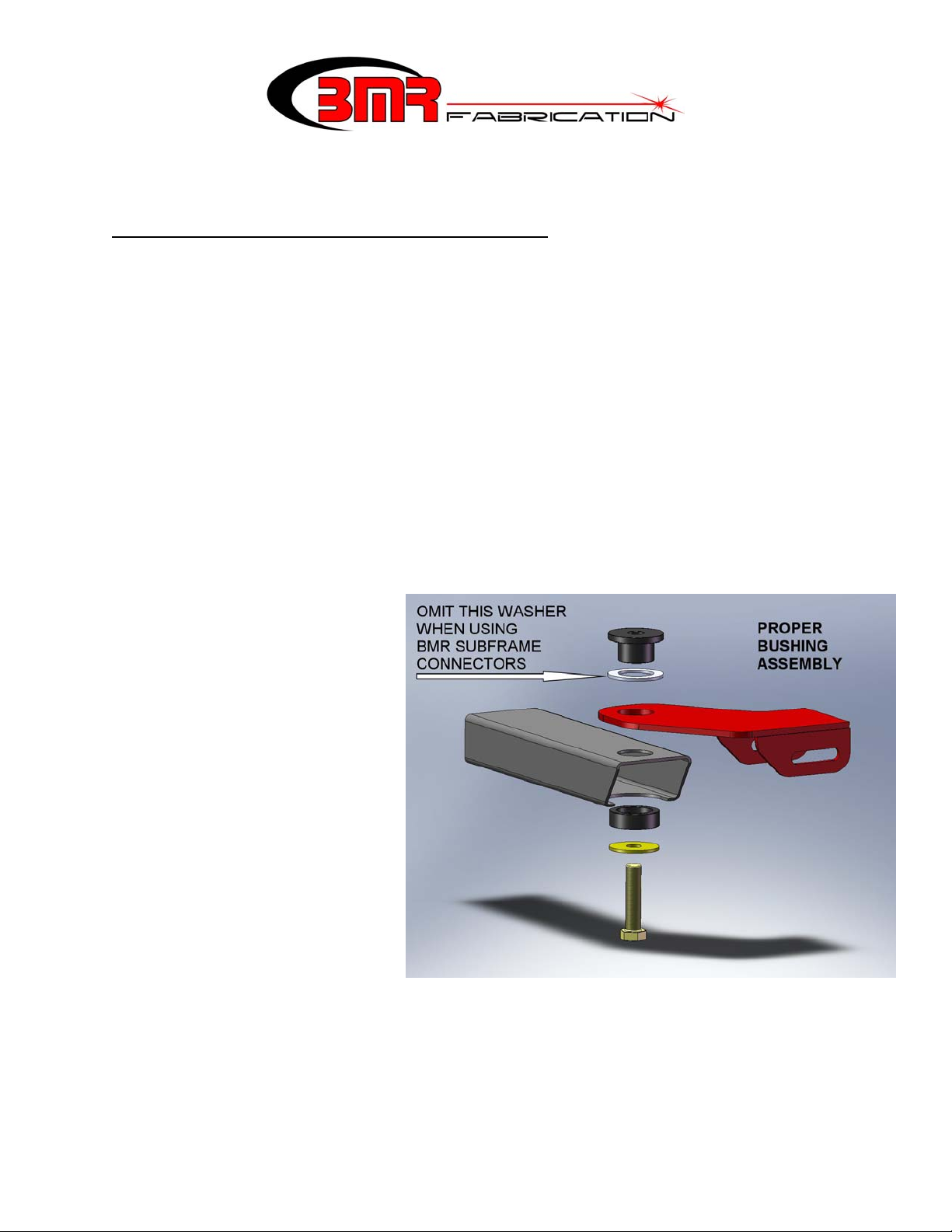
6) Begin with the driver’s side. Assemble the driver’s side frame mount, billet body mounts
and washer (if necessary) as shown in the image above. If you are using BMR subframe
connectors or any subframe connector that mounts around the body bushing, omit the
supplied aluminum spacer washer shown in the above image.
1
CROSS-MEMBER INSTALLATION (Cont.)
7) Thread the supplied bolt into the body and snug the bolt allowing the frame bracket to
rotate around the axis of the bushing.
8) Repeat steps 4-7 for the passenger side. At this stage both mounts should be installed and
you can mount the cross-member. Lift the cross-member into place and insert the
supplied ½” x 4.5” bolts, stainless washers, and nuts.
9) Tighten the body mount bolts to 150 ft/lbs.
10) Center the cross-member to the driveshaft then tighten the (4) cross-member bolts.
TORQUE ARM INSTALLATION:
- The first part of this installation involves the removal of the exhaust, fuel tank, leaf springs and
rear axle. If these items have already been removed, you may proceed to step 18.
1. Lift vehicle and support with stands
under the frame, allowing the rear end to
hang.
2. Remove the rear wheels/tires.
3. If the vehicle has exhaust installed,
remove it at this time.
4. Remove the rear shocks. Using the OE
shock bolts, bolt the supplied BMR
shock plates over the factory shock
holes.
5. In order to remove the rear leaf spring
bolts, it is necessary to remove the fuel
tank. Drain the tank using a drill pump
or siphon.
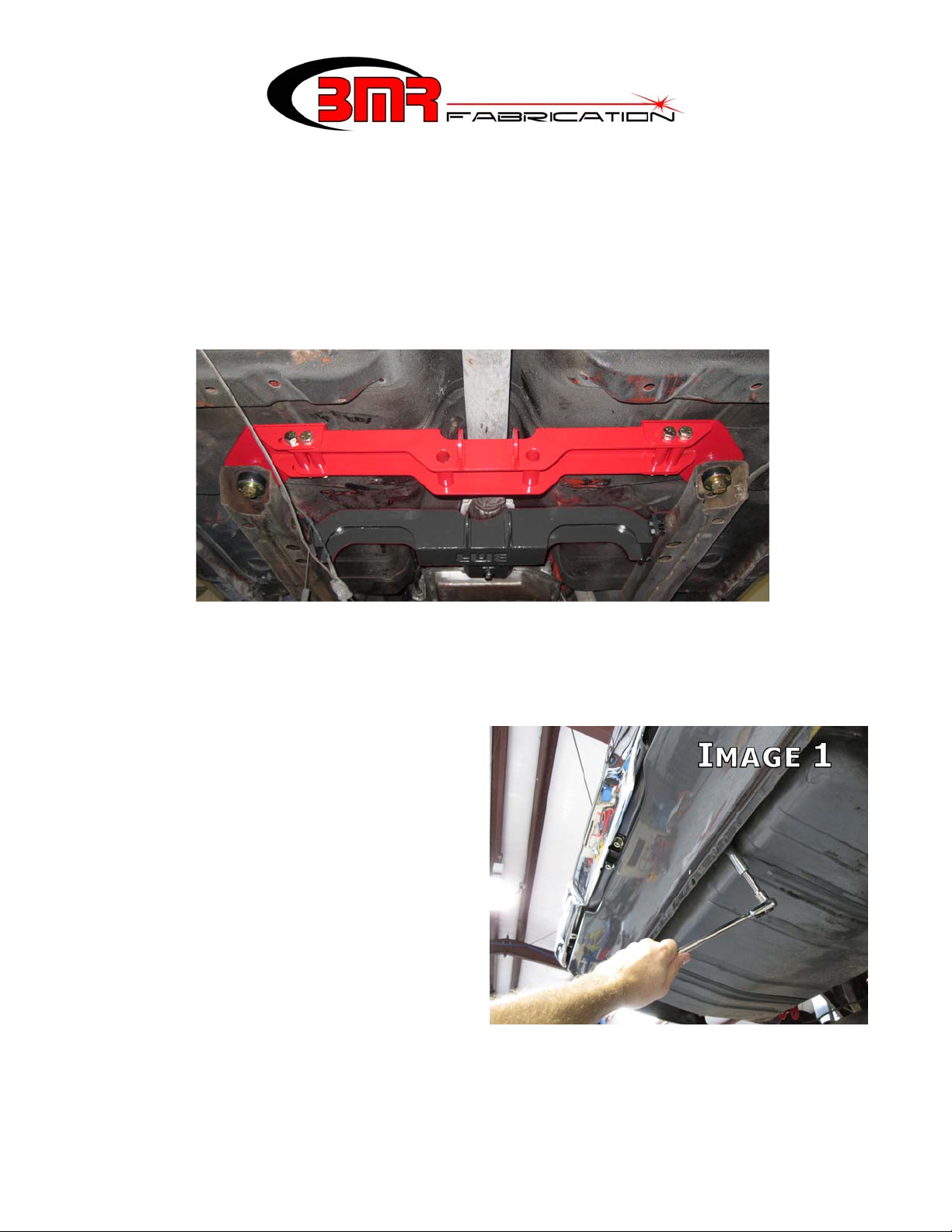
6. Support the tank and then remove the
two mounting nuts using a 9/16” deep socket. Pull the tank support straps down,
allowing the tank to be lowered. (Image 1)
7. Lower the tank far enough to access the fuel lines and electrical connectors. Disconnect
and cap the fuel lines. Lower and remove the fuel tank.
2
(CONTINUED)
8. Using a 7/16” wrench, remove the u-joint caps from the rear u-joint. Disconnect the
driveshaft from the rear end and either remove the driveshaft or tie it up out of the way.
9. Using a pair of vise grips, clamp the rubber brake hose above the axle. This will prevent
brake fluid loss when the hose is disconnected from the rear end.
10. Using a ½” wrench, disconnect the brake lines from the brake hose.
11. Support the rear end with jack stands.
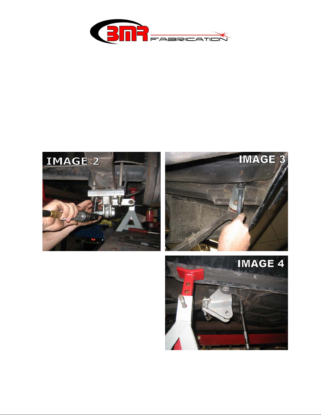
12. Using a 3/4” socket, remove the leaf spring U-bolts on the rear end. (Image 2)
NOTE: the image shown has aftermarket traction bars installed. Factory leaf spring
mounts may appear slightly different in nature.
13. Using a 5/8” socket, loosen and remove the rear leaf spring shackle bolts. Loosen the
upper shackle bolt at the frame and remove the shackles. (Image 3)
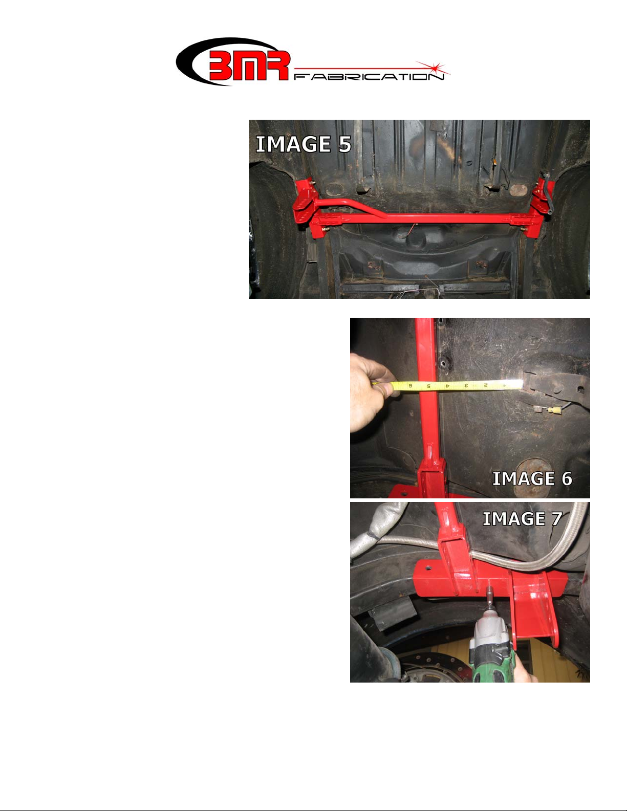
14. Using a 9/16” socket, remove the (3)
bolts on the front spring mount of each
leaf spring. (Image 4) NOTE: the image
shown had aftermarket traction bars
installed. Front leaf spring eye may
appear slightly different in nature.
15. Once all bolts are removed, remove the
leaf springs.
16. Remove the rear axle.
17. With everything removed there should
be access to the entire rear floor pan and
axle relief. Remove all muffler hangers
and any additional un-needed brackets
that might interfere with the following installation.
18. The first item to install is the shock cross member. This step can be performed by one
person but is much simpler with a helper. Have a helper hold the shock cross-member up
into place as shown in Image 5 on the next page.
3
(CONTINUED)
19. Use the fuel tank strap
mounting positions as a
reference point to locate
the cross-member
properly forward to back
and to insure that the
cross-member is mounted
square in the body. As
shown in Image 6,
measure the distance
from the relief in the
trunk pan to the main
cross tube of the cross-member. Vehicle production variance prevents a “one
measurement fits all” figure but the
measurements should fall somewhere between
4-3/8” to 4-9/16”. Re-position the crossmember until the reading from each strap
mount relief is equal and falls within the range
listed above.
20. Once properly positioned, locate the provided
sheet metal screws in the hardware pack. As
shown in Image 7, screw the cross-member
into each frame rail to hold it into position for
the upcoming steps. NOTE: the cross-
member should draw up tight against the
frame rail. Any floor pan deformations that
prevent the cross-member from fitting flush
against the frame rail should be adjusted
using a pry-bar or rubber mallet.
21. At this step the cross-member may be welded
to the subframe or bolted. If bolting is
preferred, proceed to step 22. If welding is
preferred, remove the cross-member and prep
it for welding by grinding the powdercoat off
at the weld points. Remove all paint,
undercoating and scale from the weld area on
the subframe then re-install the cross-member.
Weld a full 2” bead vertically on each end of
the plate and at least 4 inches of weld
horizontally on each side. Wire brush and
paint the weld area with rust preventive paint. Proceed to step 28.
22. If bolting the cross-member into place, position the provided frame reinforcement plate
as shown in Image 8 on the next page. Mark the frame at the center of the slot using a
grease pencil or paint marker.
4
 Loading...