

LOWERING SPRINGS FOR 2010-PRESENT CAMARO
Part #’s SP019, SP020, SP021, SP022, SP023, SP024, SP025, SP052, SP053, SP054
Required Tools:
Hydraulic jack and jack stands
Spring compressor (optional)
Wrenches: 7mm, 10mm, 15mm, 18mm, 24mm
Sockets: 15mm, 18mm, 24mm
Front Installation:
1. Lift vehicle and safely support it on stands. Remove
the wheel and tire assemblies.
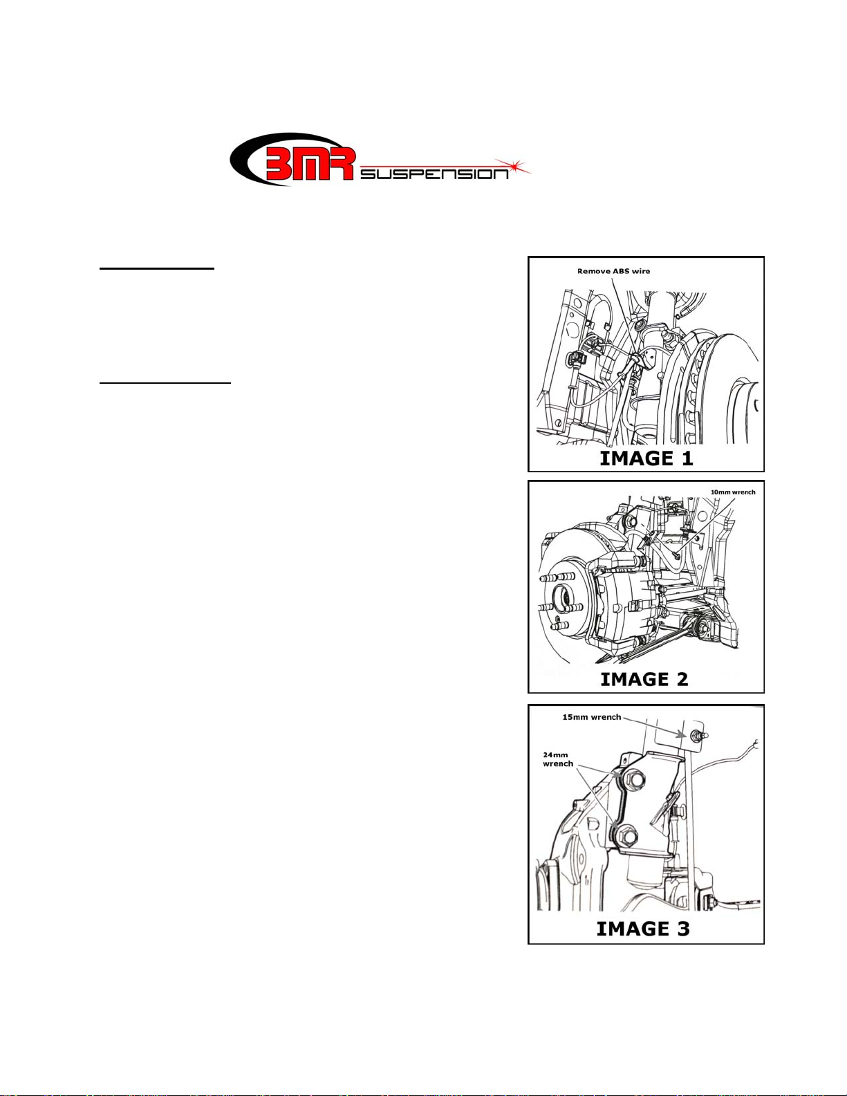
2. Locate the ABS line where it attaches to the strut.
Slide the line out of the bracket as illustrated in
IMAGE 1.
3. Using a 10mm wrench or socket, remove the brake
line retainer bolt where it attaches to the strut. See
IMAGE 2 for reference.
4. Un-bolt the sway bar end link from the strut using a
15mm wrench on the nut with a 7mm wrench in the
center to hold the shaft. See IMAGE 3 for reference.
5. Using a permanent market, grease pencil, or paint pen
mark the strut and spindle along their mating surface.
This mark will be used later during reassembly.
6. Using a 24mm wrench and socket, remove the (2)
large bolts that retain the strut to the spindle. See
IMAGE 3 for reference.
LOWERING SPRINGS FOR 2010-PRESENT CAMARO (Cont.)
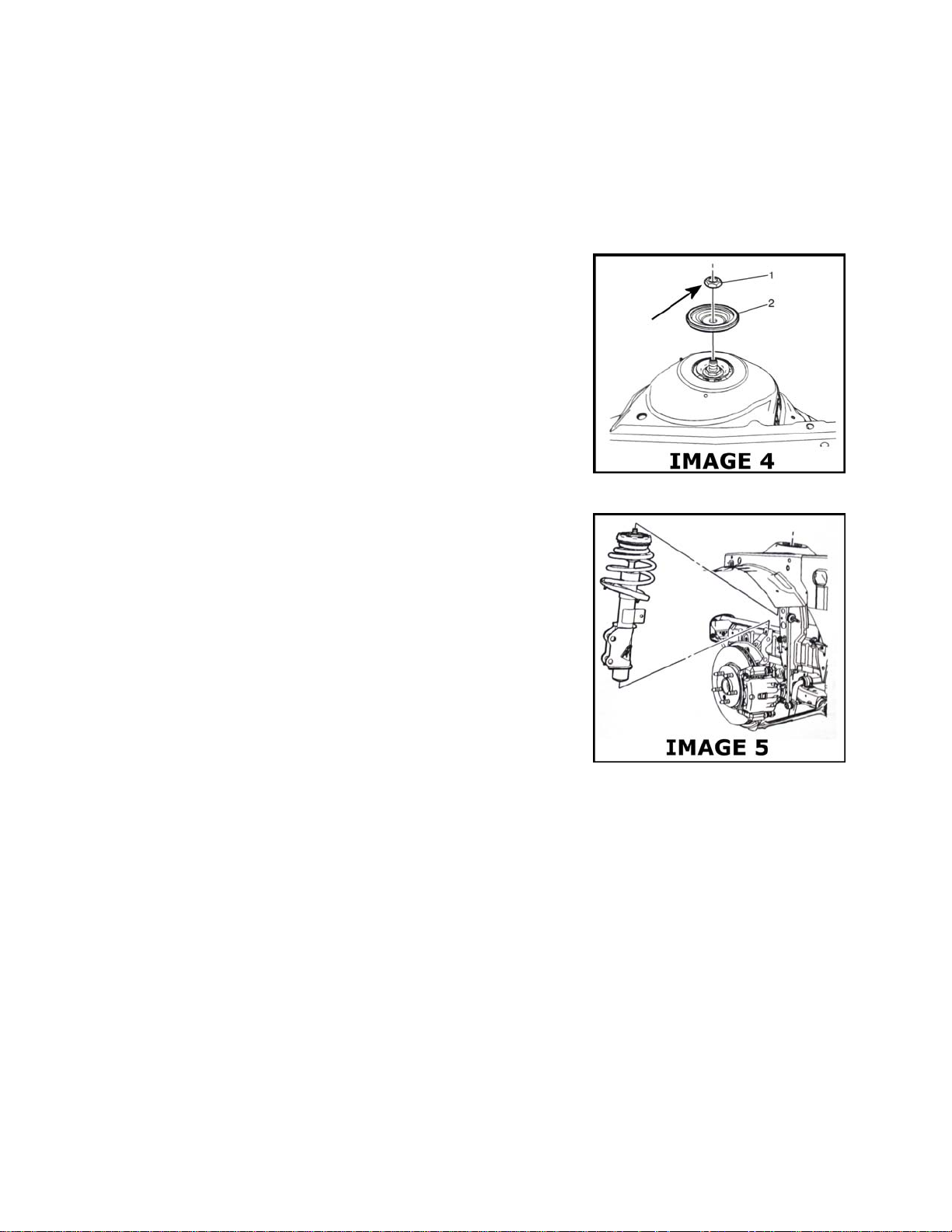
7. Open the hood and unscrew the plastic caps on top of
the strut retainer nuts.
8. Remove the upper strut nuts (item 1 in Image 4) and
strut retainers (item 2 in Image 4) using a 24mm
socket. See IMAGE 4 for reference. NOTE: Do not
remove the nut located under the strut retainer.
9. The strut should easily come out of the strut tower at
this point. If it does not, it may require a rubber mallet
to knock it loose from the tower. Remove the entire
strut/spring assembly as shown in IMAGE 5 on the
following page.
10. The next step is removing the spring from the strut. Using a spring compressor,
compress the spring to relieve tension from the upper mount. See IMAGE 6 on the next
page for reference. With the spring compressed, remove the upper strut nut using a
24mm socket.
11. Remove the individual assembly components and the OE spring as illustrated in IMAGE
6 on the following page. Place the BMR spring onto the strut and then replace each
component in the proper order as shown in IMAGE 6 on the following page. (NOTE: it
does not require a spring compressor to re-install the springs).
12. Index the spring to fit the upper and lower spring seats then tighten the upper strut nut to
52 ft/lbs.
13. Re-install the strut/spring assembly into the strut tower, placing the upper strut retainer
and nut onto the shaft to hold the assembly in place.
 Loading...