

BMR Suspension SFC013 User Manual
SUBFRAME CONNECTORS
SFC013 – 2008-Present Pontiac G8
Please read the following important information before proceeding with this installation.
• It is recommended to perform this installation on a 4 post service lift with the suspension loaded. It is
possible to use drive-on ramps as long as the full weight of the vehicle is resting on the wheels/tires and
the suspension is fully loaded. Two post lifts or floor jacks are not recommended for two reasons: they
do not load the suspension and they support the
vehicle in the same area that the subframe
connectors attach, preventing access to the
installation area.
Required Tools:
• 3/8” ratchet
• 15mm socket
• 3/8” Allen wrench or Allen socket
Installation Procedure:
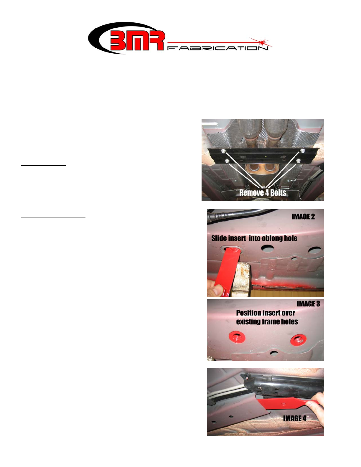
1. Lift vehicle.
2. Using a 15mm socket, remove the four bolts that
secure the OE driveshaft tunnel brace and remove
the brace.
3. Locate the 2 sets of frame inserts provided with your
BMR Subframe Connectors. The smaller of the two
fits the rear frame rails and the larger fits the front
rails. As shown in Image 2 to the right, slide the
smaller insert up through the oblong frame hole and
into the frame rail. It should fall rearward, then can
be positioned over the existing holes as in Image 3.
4. Slide the larger front frame inserts into the front rails
and position them over the existing frame holes as in
Image 4 to the right.
5. Choose a side and hold a subframe connector up into
place as shown in the image on the following page.
Insert the supplied Allen bolts and washers. Install
all six subframe connector bolts (four ½” Allen
bolts, two 10mm bolts) but do not tighten any of
them until all six bolts are partially threaded in.
NOTE: a screwdriver or tapered alignment dowel
may be used to line up the bolt holes.
1
6. Once all bolts are inserted, tighten the four Allen bolts to 45 ft/lbs.
7. Remove the 10mm tunnel brace bolts installed in the previous step.
8. Repeat steps 5-6 for the other subframe connector.
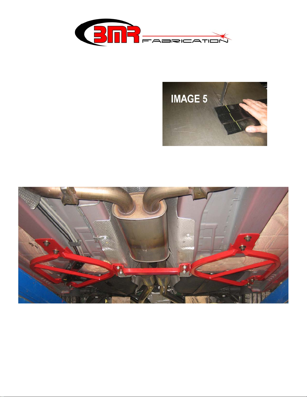
9. If re-using the factory tunnel brace, it is necessary to modify the brace for re-installation. Begin by
measuring 2” from each end and marking the tunnel brace for cutting. As shown in Image 5, cut along
the previous mark using a bandsaw, hacksaw,
or cut-off wheel. Re-install tunnel brace over
the subframe connectors and thread the 10mm
bolts back into place. Tighten bolts to 45
ft/lbs. NOTE: BMR heavy duty tunnel brace
shown below is highly recommended to take
full advantage of the subframe connectors.
When using this brace, no modifications are
necessary.
10. Lower vehicle.
Image below shown with optional BMR tunnel brace installed.
This product is an aftermarket accessory and not designed by the vehicles manufacturer for use on this vehicle. As such,
Buyer assumes all risk of any caused to the vehicle/person during installation or use of this product.
2
 Loading...