

BOXED SUBFRAME CONNECTORS – THIRD GEN. F-BODY
Part # SFC009
NOTE: Although this installation can be performed with a hydraulic jack and stands, a drive-on 4-post service lift is
recommended.
1. Lift vehicle and support. If you are not using a drive-on lift, the vehicle must be
supported with the suspension loaded. This can be accomplished by driving the front
wheels onto ramps and then placing the rear axle on jack stands.
2. Since this installation involves removal of the front control arm bolts and the car is
being supported by the rear end, it is important to do one side at a time (DO NOT
REMOVE BOTH REAR CONTROL ARM BOLTS WITH THE VEHICLE
SUPPORTED BY THE REAREND). Start by removing the drivers’ side control
arm bolt using an 18mm socket and wrench.
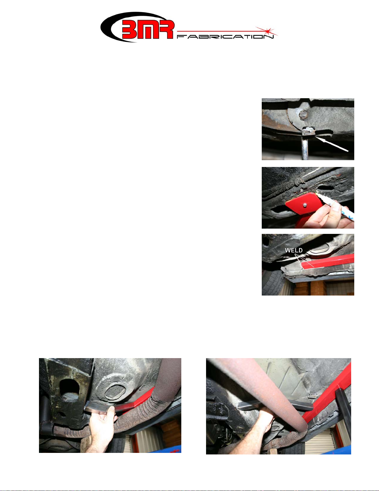
3. Install the drivers’ side sub-frame connector over the control arm mount and insert
the supplied bolt. Note: Some vehicle years had tabs in the mount area that prevent
the rear sub-frame connector bracket from fitting the mount. In these instances use a
crescent wrench or pliers to bend the tab as shown in the image above.
4. Once the rear of the Subframe connector is mounted, lift the front up and mate it to
the frame. Trace the front mounting plate onto the frame of the car using a paint
marker or similar marking tool. Trace the rear brackets as well then remove the subframe connector.
5. Grind the marked areas down to bare metal to prepare for welding. Do the same to
the sub-frame connector then re-install the sub-frame connector. Using a sheet metal
screw to secure the front of the sub-frame connector will simplify the welding
procedure. See image to the right.
6. Weld a full bead around the perimeter of the front and rear Subframe connector
plates taking care not to burn the control arm bushings in the rear.
7. Wire brush and paint the welded areas then tighten the control arm bolt to 100 ft/lbs.
8. Remove the passenger side front control arm bolt.
9. Install the passenger side sub-frame connector over the mount with the front of the
Subframe connector butted against the front frame extension as shown in the image
to the right. NOTE: In most cases it is necessary to lower the exhaust in order to
gain proper access for welding.
10. Trace the front and rear weld areas with a paint marker then remove the sub-frame connector and grind the traced areas to
bare metal. Prep the sub-frame connector also by removing the powdercoat at the weld areas.
11. Reinstall the sub-frame connector and weld the front and rear as shown in the image above.
12. Temporarily reinstall the exhaust (if removed earlier) in preparation for welding in the additional frame reinforcements.
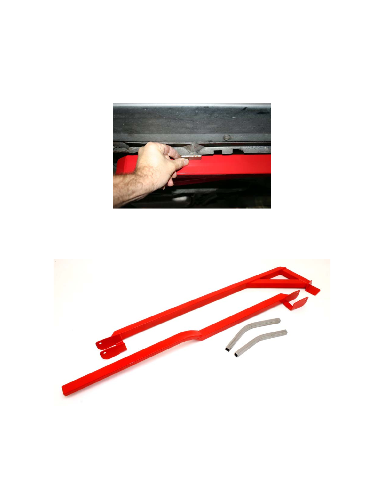
Due to the vast amount of aftermarket headers and exhaust systems available for this vehicle and the production variances associated
with them, BMR provides cut-to-length frame reinforcement tubes for the passenger side. It is necessary to fit these tubes around your
specific exhaust for proper clearance and positioning.
PAGE1
PAGE 2
13. Begin by holding one of the tubes up into the approximate position and start trimming the ends a little a t a time until you get
a good fit from the sub-frame connector to the inner frame rail. Try to stagger the tubes on the frame rail providing as much
exhaust clearance as possible. See images to the right for examples.
14. Once the two frame reinforcements have been properly fit, grind the sub-frame and the sub-frame connector at the weld
points and weld into place.
15. Wire brush and paint all weld points and re-install the exhaust if previously removed.
16. Tighten the control arm bolt to 100 ft/lbs.
17. Lower vehicle.
BMR Subframe connectors ship with additional reinforcement plates that may be welded in if desired. They are designed to join the
factory pinch welds on the rocker panels to the Subframe Connectors. The reinforcement plates are not necessary for light duty street
applications but are recommended for aggressive road racing, high horsepower drag raci ng a p pl i cati on s or whe n using the BMR Trak
Pak or Xtreme Duty torque arms with weld-in cross-member. See image below for installation example.
WWW.BMRFABRICATION.COM
This product is an aftermarket accessory and not designed by the vehicles manufacturer for use on this vehicle. As such, buyer
assumes all risk of any damage caused to the vehicle/person during installation or use of this product.
PAGE 2
 Loading...