

Please read the following important information before proceeding with this installation.
• It is recommended to perform this installation on a 4 post service lift with the suspension loaded.
•
Tools required:
o Pry-bar
o Rubber mallet
o MIG welder
o Sawzall or Cut-off wheel
o ¾” wrench
o ¾” and 15/16” sockets
o Drill with ½” bit
Installation:
HEAVY DUTY BOXED SUBFRAME CONNECTORS
SFC006 – 1967-1969 Camaro and Firebird
Two post lifts or floor jacks cannot be used because it is necessary to separate the body from the
frame during the installation.
This installation does not account for brake and fuel lines that may need relocation due to
interference. Please have all the materials necessary to perform modifications to these items
before proceeding.
1. Before raising the vehicle it is necessary
to remove the lower portion of the rear
seat and the front seats to gain access to
the floor pan area. The front seats unbolt
using a ½” or 9/16” socket depending on
the year the vehicle was manufactured.
The rear lower seat can be removed by
pushing in on the front of the seat and
lifting upward at the same time. There is
a seat retainer on both the driver’s side
and the passenger side lower seat that must be unfastened to lift the seat upward. Once released, remove
the seat and place aside.
2. Pull up the carpet and insulation from the rear foot well to gain access to this area.
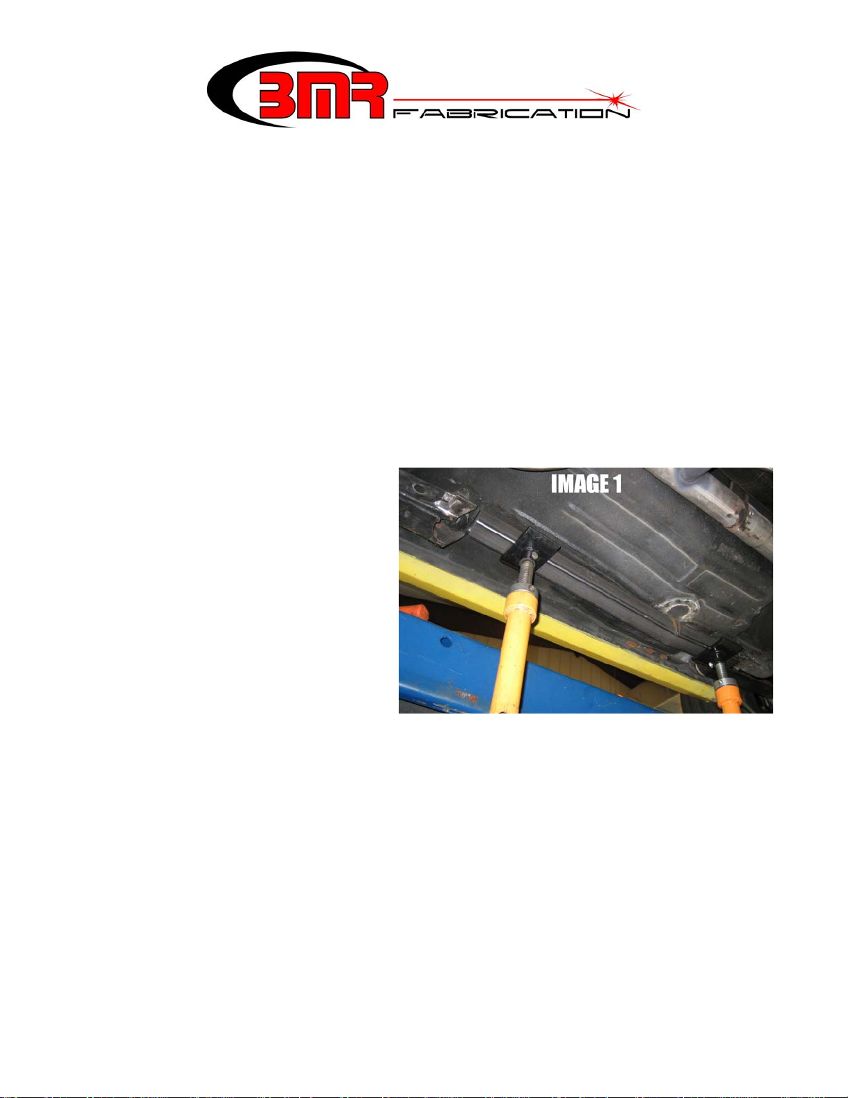
3. Lift the vehicle. Position one of the subframe connectors up against the floor as shown in Image 1. The
subframe connector should be centered to the front subframe and the rear subframe.
4. Once properly positioned, trace the subframe connector on the floor pan with a grease pencil or paint
marker. This will be your cut-line.
5. SEE NOTES BELOW BEFORE PROCEEDING: Using a Sawzall, body saw, or cut-off wheel carefully
cut on the inside of the lines and remove the cut portion.
NOTE: make your cuts smaller than needed, it is always easier to widen the hole with a second cut than to
make the hole too large and have a big gap to weld.
1
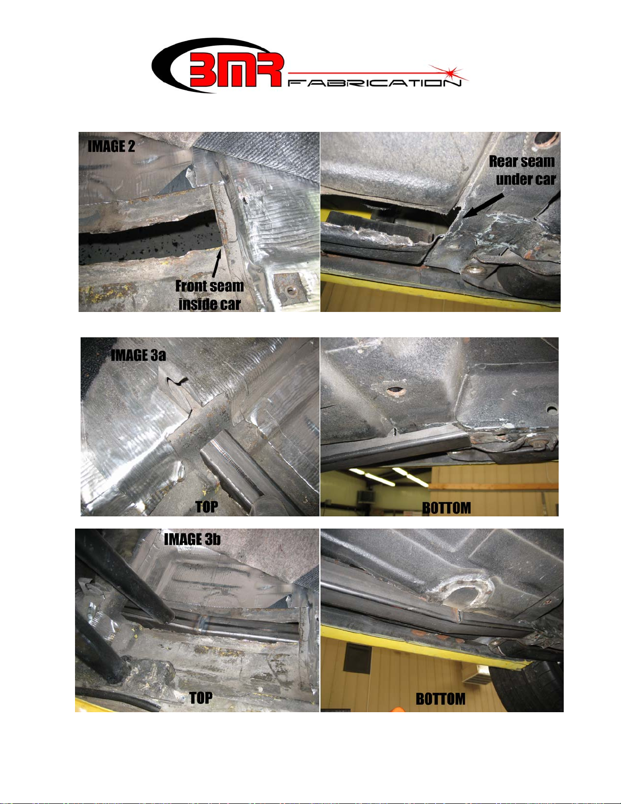
NOTE: do not cut the entire length of the foot well. Stop the cuts at the body seams as shown in Image 2
below. The rear body seam is only visible from underneath the car while the front body seam is only visible
from inside the car.
6. Test-fit the subframe connector up into the slot. It should slide rearward, up against the rear subframe as
shown in Image 3a and 3b below. Once properly fit, remove the subframe connector.
2
 Loading...