

a
Please read the following important information before proceeding with this installation.
• It is recommended to perform this installation on a 4 post service lift with the suspension loaded.
•
• While it is not necessary, to get the most out of your BMR subframe connectors it is highly
Tools required:
o Pry-bar
o Rubber mallet
o 9/16” socket
o 15/16”, ¾” socket
o ¾” wrench
o Drill with ½” bit
HEAVY DUTY BOXED SUBFRAME CONNECTORS
SFC005 – 1967-1969 Camaro and Firebird
Two post lifts or floor jacks cannot be used because it is necessary to separate the body from the
frame during the installation.
This installation does not account for brake and fuel lines that may need relocation due to
interference. Please have all the materials necessary to perform modifications to these items
before proceeding.
recommended to install a set of BMR’s Delrin Body Mount Bushings to further reduce chassis
flex in the vehicle.
Installation:
1. Before raising the vehicle it is necessary to remove the lower
portion of the rear seat to gain access to the floor pan area
under the seat. This can be accomplished by pushing in on
the front of the seat and lifting upward at the same time.
There is a seat retainer on both the driver’s side and the
passenger side that must be unfastened to lift the seat
upward. Once released, remove the seat and place aside.
2. Choose a side to begin then locate the rear-most body mount
bushing on the front subframe. Using a 15/16” socket,
remove this bolt. Loosen the next bolt forward also but do
not remove it. The subframe should separate from the body.
3. Using a pry-bar, pry the subframe down until the factory
body mount bushing can be removed. The bushing is a twopiece design, one portion on top of the subframe and one
below.
NOTE: depending on the condition of the vehicle, this area is subject to rust and scale. Before proceeding,
inspect the area for damage and repair, if necessary.
b
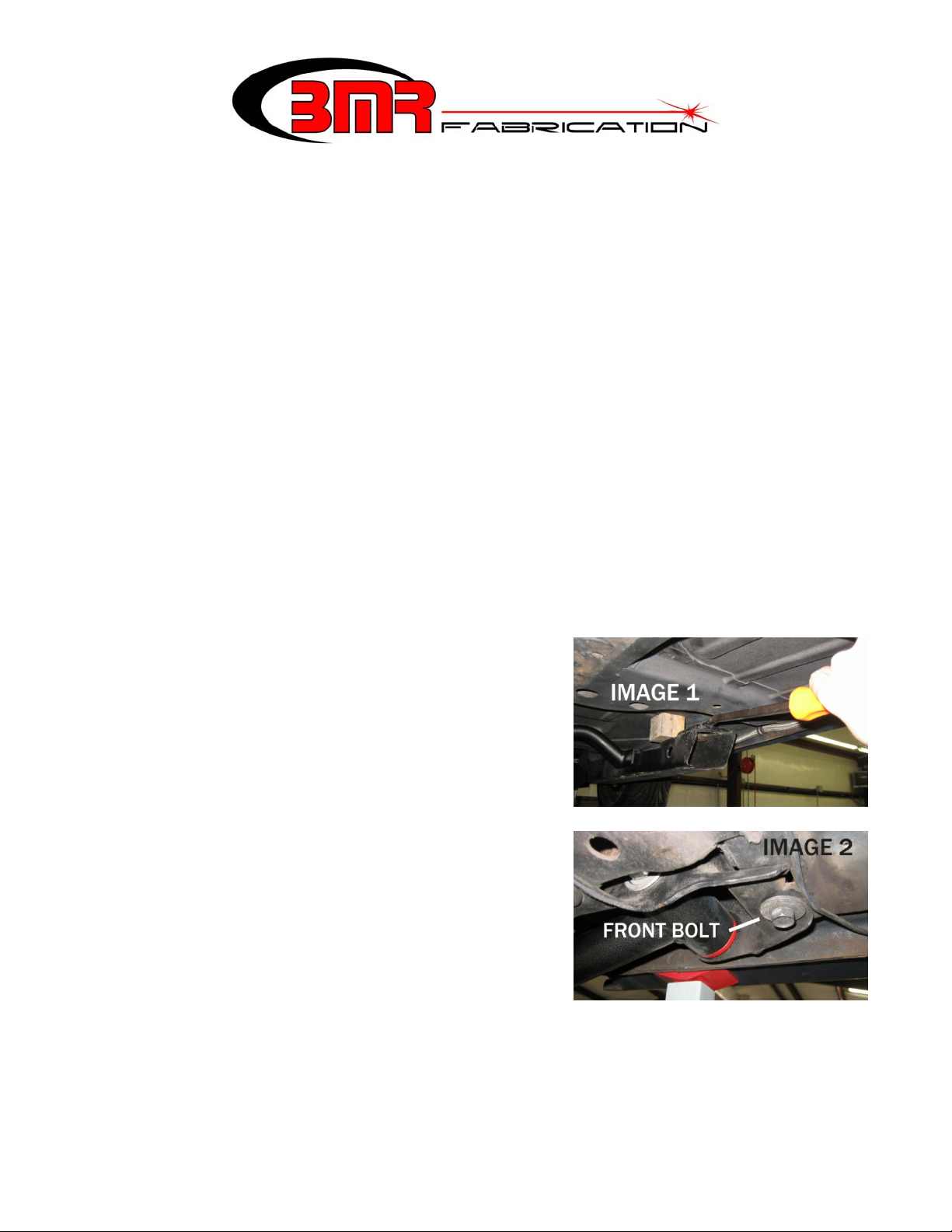
4. Using a pry-bar, pry downward on the subframe connector and insert a block of wood as shown in Image
1. Lift the appropriate subframe connector into place and slide it over the rear of the subframe. Insert the
mount bushing from the top.
5. Remove the block of wood, allowing the subframe to return to its normal location.
6. Using a 9/16” socket, remove the front bolt from the leaf spring mount. (See Image 2)
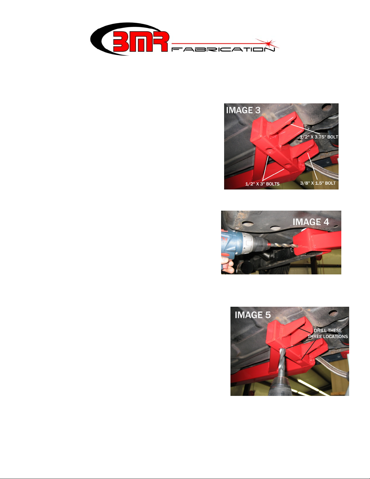
7. Lift the rear of the subframe connector up until it lines up
with this bolt hole as shown in Image 3 below. Insert the
3/8” x 1.5” bolt, washer and lock washer into the hole and
loosely tighten.
8. Insert the lower portion of the body mount bushing on the
front and insert the supplied new bolt and washer. Loosely
tighten until the subframe is drawn back up against the floor
pan. NOTE: If possible, use a jack to raise the subframe.
This will prevent excess stress on the threads of the body
mount bolt and nut.
9. Using the holes in the front subframe connector box as a drill
guide, drill through the factory subframe with a ½” drill bit.
See Image 4. It may be necessary to remove the exhaust or use a 90 degree drill to gain access to the
inside drill area.
10. Insert the ½” x 1” bolts, washers and nuts into the holes and
tighten to 110 ft/lbs.
11. Using the remaining rear holes in the back of the subframe
connector as drill guides, drill up through the floor pan
using the ½” drill bit. See Image 5.
12. Inspect the area around this mounting location for gaps
between the subframe connector and floor pan. Due to
production variance, age, vehicle damage, etc., it may be
necessary to insert a shim washer into these areas before
installing the mounting bolts. BMR supplies 8 shim washers for use in these locations.
13. Insert the bolts from the top using the appropriate sizes illustrated in Image 3. NOTE: it may be
necessary to pull the carpet back to gain access to these holes.
14. Once the bolts are inserted, install a washer and nut on each
bolt then tighten to 110 ft/lbs.
15. Tighten the 3/8” bolt to 25 ft/lbs.
16. Tighten both front body mount bolts to 180 ft/lbs.
17. Repeat steps 2-16 for the other side.
18. Re-install the rear seat.
19. Lower vehicle.
This product is an aftermarket accessory and not designed by the vehicles manufacturer for use on this vehicle.
As such, Buyer assumes all risk of any caused to the vehicle/person during installation or use of this product.
WWW.BMRSUSPENSION.COM
 Loading...