

BMR Suspension SB042 User Manual
SB042 INSTALLATION INSTRUCTIONS
REQUIRED TOOLS:
Jack and jack stands
13mm, 15mm, 18mm, 19mm, 9/16”, ¾” sockets and wrenches
5/16” Allen wrench
Pry bar
INSTALLATION:
1. Lift vehicle and safely support with stands
under the frame. It may also help the
installation to position the jack under the rear
end and lift it slightly to remove some of the
load off the control arm bolts.
2. If working on jack stands, remove both rear
wheels/tires to gain better access to the work
area. NOTE: the installation pictured was done
on a 2-post service lift and the wheels/tires
were left installed throughout the installation
process.
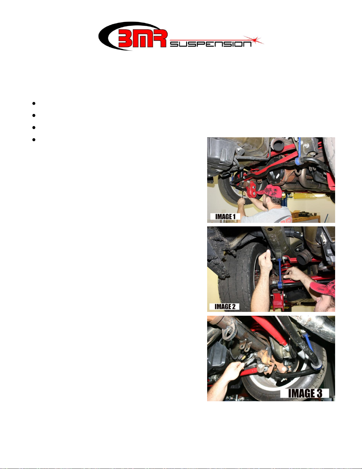
3. Using a 13mm socket, un-bolt the outer sway
bar mounting bushings as shown in IMAGE 1.
4. Using a 15mm socket, un-bolt the sway bar
end links as shown in IMAGE 2.
5. Remove the factory sway bar.
6. Starting with the drivers’ side of the car,
remove the control arm bolt at the axle using
an 18mm wrench or socket.
7. Directly above the control arm bolt is the axle
damper weight that must also be removed for this installation. Remove it using a 15mm
socket or wrench as shown in IMAGE 3.
1
SB042 INSTALLATION INSTRUCTIONS
CONTINUED
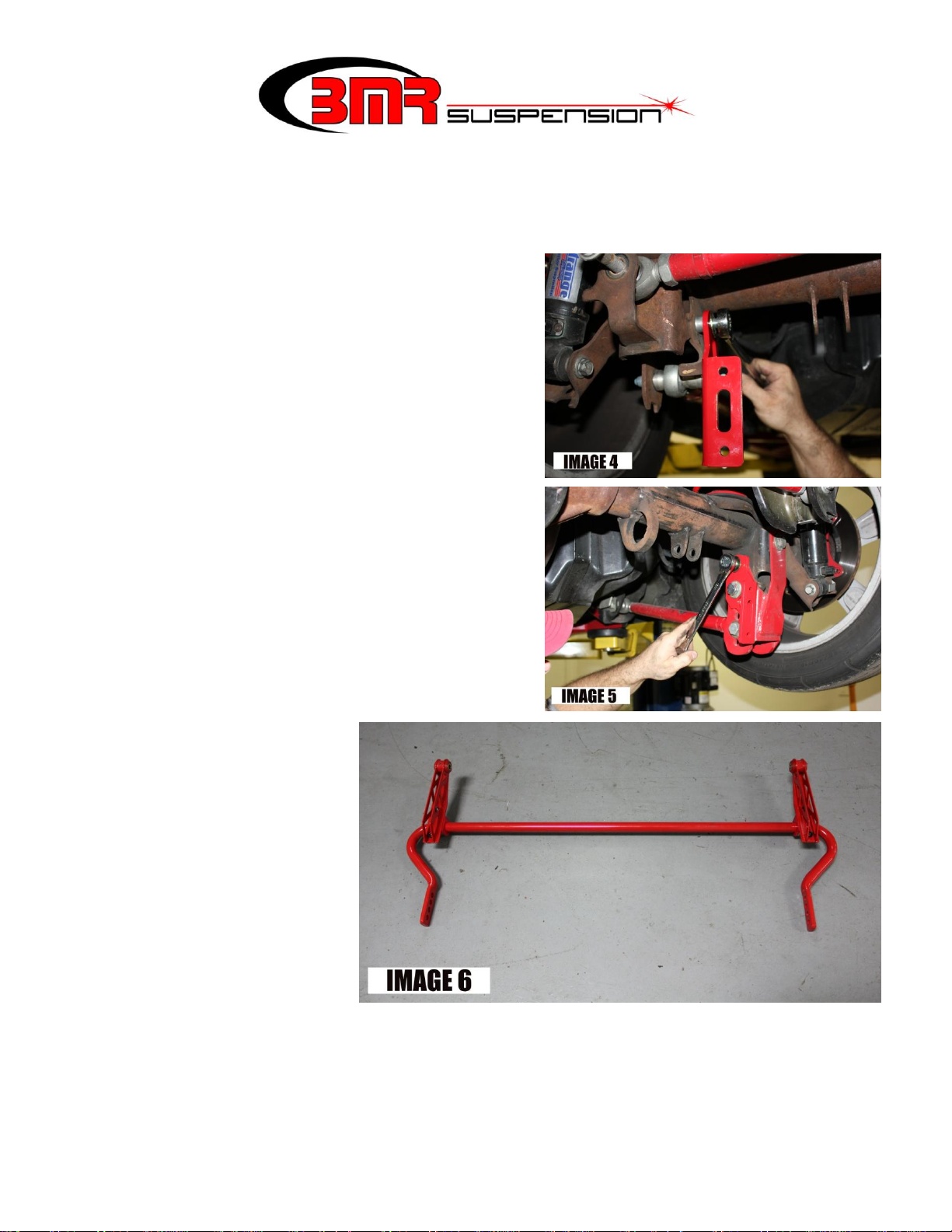
8. Install the BMR mounting bracket as shown in
IMAGES 4. If you have BMR CAB005Control
Arm Relocation brackets already installed on
your vehicle, you can simply bolt the bracket in
place using the hardware that was provided
with your Control Arm Relocation brackets
(See images on final page of instructions). If
you do not have BMR Control Arm Relocation
brackets installed on your vehicle, bolt the
BMR sway bar bracket to your axle using the
supplied 12mm x 30mm bolt, washer, and
spacer as shown in IMAGE 4.
9. Once the bracket is installed, tighten the
control arm bolt to 129 ft/lbs. and the damper
bolt to 45 ft/lbs.
10. Proceed to the passenger
side and install the BMR
supplied bracket as
shown in IMAGE 5. This
side does not require a
spacer. Tighten to 129
ft/lbs.
11. Using the provided 1”
Energy Suspension
bushings, connect the
BMR end links to the BMR sway bar as shown in IMAGE 6. Use the provided 3/8” Allen
bolts, nuts, and washers for this connection.
2
 Loading...