

SB030 SWAY BAR KIT
FRONT SWAY BAR INSTALLATION
SB016 – 2010-2012 CHEVROLET CAMARO
NOTE: Due to the elevated height necessary for removing and installing the sway bar on this particular application, it is
recommended to perform this installation on a 2 post service lift to get adequate height.
RECOMMENDED TOOLS:
10mm, 15mm, 18mm wrench 3/8” drive ratchet w/13mm socket 6mm Allen wrench
INSTALLATION:
1. Lift vehicle and remove both front wheels/tires.
2. If you do not have a ZL1, skip this step and proceed to step 3. On the ZL1,
you will need to remove the plastic panel that covers the bottom of the engine
compartment. Remove the 14 bolts using a 10mm socket then remove the
panel to gain access to the sway bar.
3. Using a 15mm wrench (18mm for the 2012-newer), remove the nuts on the
outer sway bar links. (IMAGE 1)
4. Access the frame mounts through the wheel wells as shown. Using a 13mm
socket, remove the two bolts that retain the mounting bushings. (IMAGE 2)
5. Using an 18mm socket, loosen the (2) motor mount nuts as shown in IMAGE
3. Place a block of wood under the oil pan and lift the motor approximately 2
inches to make room for the sway bar removal.
6. Begin working the sway bar out by rotating it up and
around the tie rod on the drivers’ side of the car,
pushing and rotating the bar towards the passenger side.
The sway bar can be pulled through from the passenger
side by rotating and twisting it around any obstacles. In
order to get the sway bar completely out, the bar must
be rotated downward in the last step. (IMAGE 4)
1
FRONT SWAY BAR INSTALLATION (Continued)
SB016 – 2010-2012 CHEVROLET CAMARO
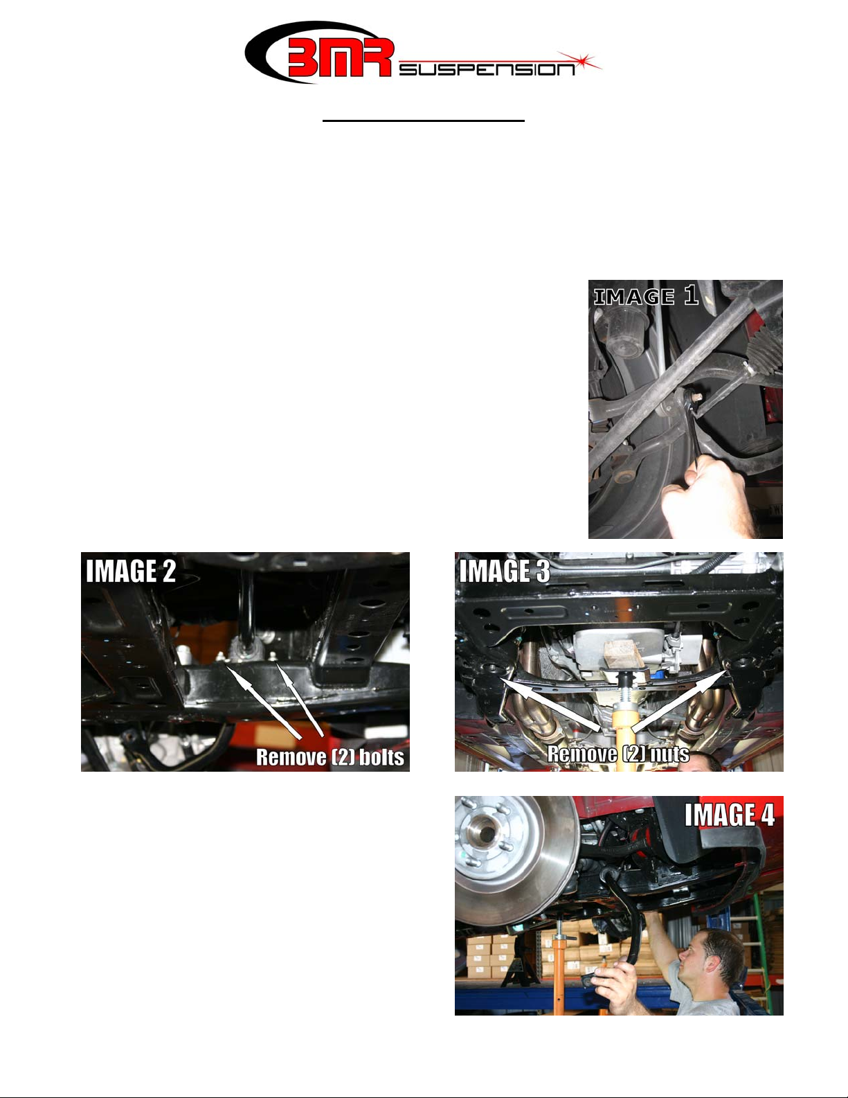
7. Begin sliding the BMR sway bar in from the
passenger side the same way the OE bar was removed.
Rotate and slide the bar in a spiral pattern until it gets
to the drivers side. (IMAGE 5)
8. Grease the inside of the BMR polyurethane bushings.
Position the bushings over the straight section of the
sway bar. The bushings go to the outside of the
welded thrust washers on the sway bar.
9. Place the provided bushing saddle over the
polyurethane bushings and thread the OE nuts into
place. Tighten.
10. Connect the outer end links to the sway bar and
tighten.
11. Lower the engine and re-tighten the mounting nuts.
12. Grease the fittings on the sway bar mounting bushings until grease is visible protruding from the bushing.
13. If you have a ZL1, re-install the underbody plastic covers.
14. Re-install wheels, tires and lower vehicle.
2

REAR SWAY BAR INSTALLATION
SB017 – 2010-2011 CHEVROLET CAMARO
RECOMMENDED TOOLS:
15mm wrench
13mm socket
3/8” drive ratchet
5mm Allen wrench
INSTALLATION:
1. Lift the vehicle and safely support it under the frame
rails.
2. Using a 15mm wrench or socket, remove the nuts
from the sway bar end links. (IMAGE 1) NOTE: A
5mm Allen wrench may be necessary to prevent the
center stud of the end link from spinning while
removing this nut.
3. Using a 13mm socket, remove the bolts that hold the
sway bar to the rear suspension cradle. (IMAGE 1)
4. Remove the rear sway bar. NOTE: Most exhausts will
allow the swaybar to be removed without lowering the
exhaust. Sometimes it is possible to remove a wheel
and slide the swaybar out from the side.
5. Slide the provided polyurethane bushings over the
swaybar on the outside of the thrust washers as shown
in IMAGE 2.
6. Position the BMR sway bar into place and install the
provided saddles over the bushings. Insert the OE
bolts and hand-tighten.
7. Insert the end links into the desired sway bar hole and
tighten both nuts. See following page for swaybar hole
recommendations.
8. Tighten the mounting bushings to 15 ft/lbs.
9. Lube both bushings with a synthetic bushing lube.
10. Lower vehicle.
FRONT BAR RATES
Furthest hole (farthest away from main portion of bar) 98% stiffer than OE front bar
Middle hole 146% stiffer than OE front bar
Closest hole (closest to main portion of bar) 214% stiffer than OE front bar
REAR BAR RATES
Furthest hole (farthest away from main portion of bar) 100% stiffer than OE rear bar
Middle hole 175% stiffer than OE rear bar
Closest hole (closest to main portion of bar) 300% stiffer than OE rear bar
WWW.BMRSUSPENSION.COM
This product is an aftermarket accessory and not designed by the vehicles manufacturer for use on this vehicle. As such, buyer assumes all risk of any damage caused to vehicle/person during installation or use of this product.
3
 Loading...