

SB035 INSTALLATION INSTRUCTIONS
TOOLS REQUIRED:
Wrenches – 9/16”, 11/16”, 8mm, 19mm
Sockets – 9/16”
3/8” drive ratchet
Electric drill with 3/8” drill bit
INSTALLATION:
1. Lift rear of vehicle and support with jack stands under the frame rails.
2. Remove factory rear sway bar, if equipped.
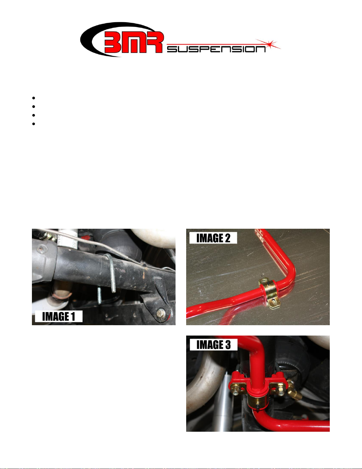
3. Position the two supplied U-bolts over the axle as shown in IMAGE 1.
4. Lube the inside of the polyurethane bushings with the supplied grease then position the bushings
over the sway bar on the outside of the thrust washers as shown in IMAGE 2.
5. Place the bushing saddles over the bushings as shown in IMAGE 2.
6. Using a helper or a stand to hold one side, lift the sway bar up into position. Place one of the
supplied axle brackets over the U-bolt on the axle and then connect the sway bar bushing saddle
to the U-bolt, “sandwiching” the axle bracket between the bushing and the axle.
7. Repeat for the other side. The mount should look like IMAGE 3 when connected properly.
8. Measure side-to-side to make sure the
sway bar is properly centered. Also,
viewing from directly underneath the
axle, verify that the sway bar is on the
centerline of the axle and the brackets
are not crooked.
9. Once the sway bar is properly
positioned, tighten all (4) nuts on the Ubolts using a 9/16” socket.
1
SB035 INSTALLATION INSTRUCTIONS (Cont.)
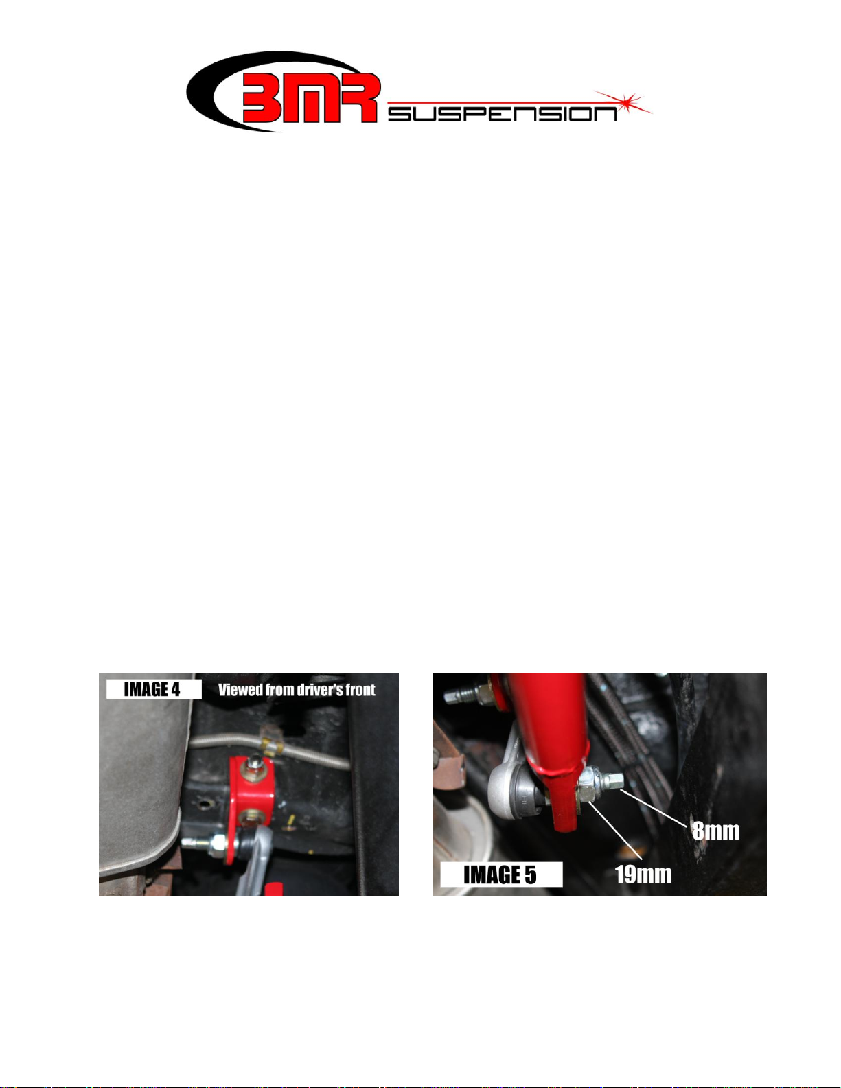
10. Now it is necessary to load the axle in order to properly position and connect the end link
mounting brackets. Lift up the rear end until the axle is approximately at ride height relative to
the body.
11. Position an end link in the middle hole of the sway bar on the inside of the bar and tighten the
nut using a 8mm wrench to hold the stud and a 19mm wrench to tighten the nuts.
12. Connect the correct frame bracket to the other end of the end link using IMAGE 4 as an
example.
13. Rotate the bar upwards until the end link bracket sits flush on the frame. The end link should be
as vertical as possible to insure that the sway bar works properly with no bind. NOTE: Some
exhaust systems may have an exhaust hanger mounted in this area. It will be necessary to modify
the hanger to provide proper clearance for the end link mounting bracket.
14. Once the sway bar bracket is in the proper position, either trace the bracket with a marker or
trace the bolt holes for drilling. Duplicate steps 11-13 for the other side.
15. Lower the sway bar and drill (4) 3/8” holes on your previous marks.
16. Mount the sway bar brackets to the frame using the supplied 3/8” x 1” Grade 8 bolts, nuts, and
flat washers. NOTE: Make sure when you mount the frame brackets that the horizontal bolt goes
in from the rear of the car pointing forward and the vertical bolt faces upward with the nut on
top. If the bolts are not inserted in these positions, the end link will not have sufficient clearance
on the mounting bracket. NOTE: Always put the flat washer on the slotted portion of the
bracket. The finished installation of the bracket should look like IMAGE 4.
17. Rotate the bar upward and connect the end links to the brackets. Tighten the end links using a
8mm wrench to hold the stud and a 19mm wrench to tighten the nuts. (IMAGE 5)
18. Pump approximately 5-8 pumps of grease into the grease fittings on the sway bar bushings then
lower the vehicle.
2
 Loading...