

KM018, KM020 TUBULAR K-MEMBER INSTALLATION INSTRUCTIONS
2011-Present Ford Mustang, GT500
Please take a moment to verify contents of this package before proceeding with the installation. It is the sole responsibility
of the Purchaser to inventory these contents before vehicle disassembly. BMR Suspension will not be held responsible for
additional labor time, service lift charges, etc. that may occur due to missing items.
INSTALLATION:
1. Lift vehicle and safely secure using stands under the frame rails. Remove both front wheels/tires.
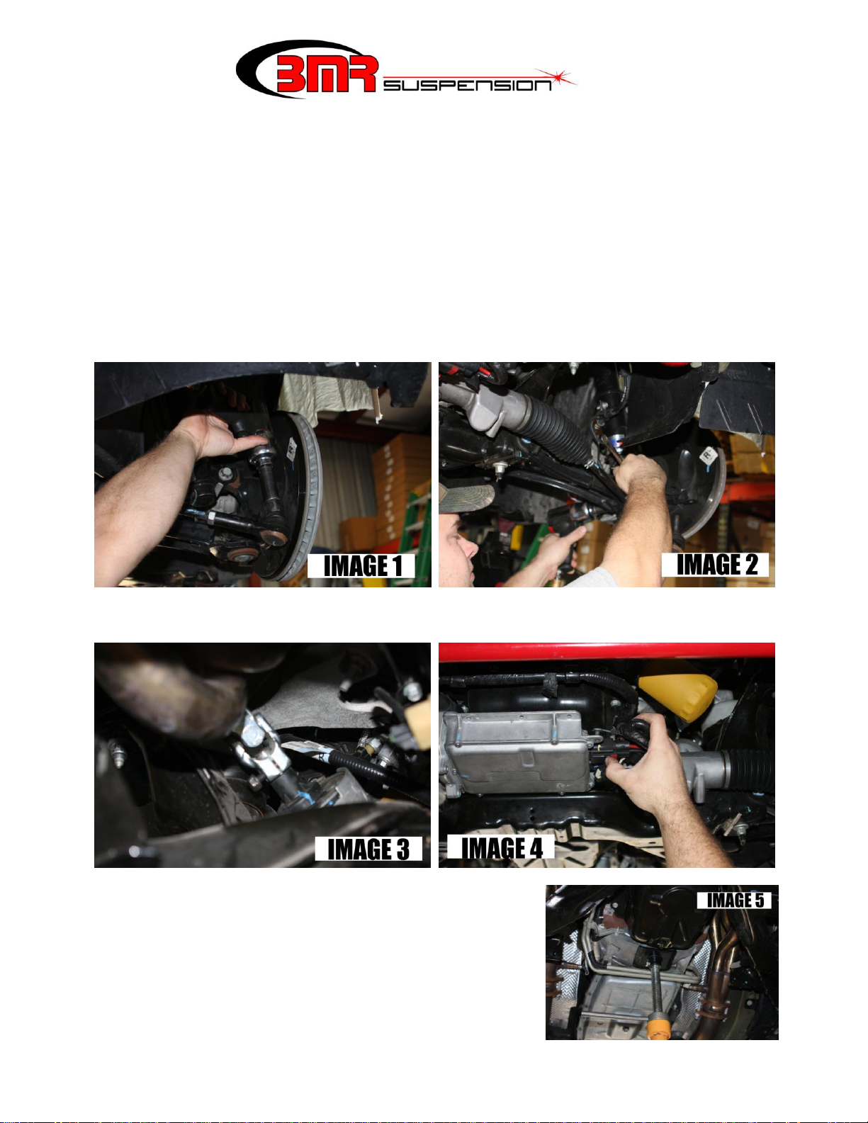
2. Using an 18mm deep socket, loosen the outer tie rod end nuts and knock them loose from the
spindles with a brass hammer. (IMAGE 1)
3. Loosen and remove the A-arms’ ball joint cross-bolts using a 15mm wrench and an 18mm socket.
Knock or pry the ball joint loose from the spindle. (IMAGE 2)
4. Remove the front steering shaft bolt using a 13mm socket or wrench. (IMAGE 3)
5. Unplug the wires from the front of the rack and pinion as shown in IMAGE 4.
6. Using a 15mm socket with an extra long extension, remove
both motor mount nuts from the top.
7. Support the motor and transmission in preparation for
removal of the K-member and A-arms. It is recommended
to place a stand under the transmission bellhousing as shown
in IMAGE 5 to the right.
8. Using an 18mm socket, remove all 8 K-member bolts and
lower the K-member/A-arm/Rack assembly.

KM018, KM020 TUBULAR K-MEMBER INSTALLATION INSTRUCTIONS
(Continued)
9. Using an 18mm socket, remove the (3) bolts that connect the rack and pinion to the OE K-member.
(IMAGE 6)
10. Using the provided 12mm x 130mm bolts, nuts, and washers, bolt the rack to the BMR K-member
using a 19mm wrench and socket. Insert the provided 14mm x 100mm bolt, nut, and washers into
the rear mount of the rack and tighten using a 22mm wrench and socket. (IMAGE 7)
11. If you are re-using the OE A-arms, remove all 4 rear A-arm bolts from the OE K-member using a 21mm
deep socket. Using an 18mm socket,
remove both front A-arm bolts then
remove the A-arms.
12. Install the BMR K-member onto the
car using the factory mounting
hardware. Tighten all 8 K-member
mounting bolts to 85 ft/lbs. using an
18mm socket. Lower jack and
remove.
13. Locate the BMR motor mount
hardware and install it as shown in
IMAGE 8. NOTE: The assembly is
shown with the K-member out of the
car for illustrative purposes only.
Line up the motor stands with the
mounting bushings on the K-member. It may be necessary to shift the K-member or the motor slightly
to get the holes lined up. Once lined up, position the other polyurethane bushings and supplied 2”
washers on the bottom of the K-member mounting bracket and insert the supplied 3/8” bolt. The
bushings should “sandwich” the K- member mount when installed correctly. Tighten the bushing
mounting bolts to approximately 15 ft/lbs. using a 9/16” wrench and 9/16” socket.
14. Re-attach the tie rod ends to the spindle and tighten using the 18mm deep socket.
15. Plug the electrical connectors back into the rack and pinion.
16. Re-install the steering shaft and tighten using a 13mm socket.
CONTINUED
 Loading...