

LS1 TUBULAR K-MEMBER INSTALLATION
PART # KM019, KM019-1
Required Tools:
Jack and Jack stands or Service Lift
Wrenches: 8mm, 10mm, 11mm, 13mm, 18mm
Sockets: 10mm, 13mm, 18mm, 21mm, 15/16”
Various ratchet extensions and universal joints
Brass Hammer or Pickle Fork
Installation Procedure:
1. Using an 8mm wrench, remove the positive cable on the battery.
2. Using a 15mm wrench, loosen the serpentine belt tensioner and remove the belt from the alternator.
3. Lift car so that the factory K-Member is at least 18” from the ground. Support car with jack stands under frame rails.
4. Remove wheels/tires.
5. Using a 13mm socket and wrench, remove the front sway bar.
6. Using an 18mm wrench, remove both power steering lines and cap hoses to prevent fluid loss.
7. Using a 13mm and a 15mm socket, remove all three (3) bolts holding the alternator in place, unplug wiring harness, and
remove the alternator. This is necessary in order to access the factory motor mount bolt.
8. Support the motor with a jack and block of wood under the oil pan.
9. Using a 13mm socket and wrench, remove the drivers’ side motor mount bolt.
10. Using an 18mm socket and wrench, remove the two (2) bolts holding the starter in place. Starter may be removed completely
or it may hang, suspended by the battery cable.
11. Using a 13mm socket, remove all four (4) bolts holding the passenger side motor mount to the motor. This will require a
combination of extensions and flexible u-joints in order to access all of the bolts.
12. Remove the cotter pins from both outer tie rod ends. Using an 18 mm wrench loosen both castle nuts until the nut is flush
with the top of the stud. Using a brass hammer, tap the castle nut until the tie rod breaks loose from the spindle. This may
also be accomplished by using a pickle fork, if available.
13. Using a 15mm wrench and 18mm socket, loosen both the rack
and pinion mounting bolts. It is not possible to remove the
driver’s side bolt until the K-member is lowered.
14. Using an 11mm wrench, remove the steering shaft bolt
located directly above the rack and pinion.
15. Using a 10mm socket, remove all four (4) brake line retaining
tab bolts that attach to the side of the K-member.
16. Using a 21mm socket and wrench, remove the lower A-arm
mounting bolts for both the drivers’ and passengers’ side.
17. Using an 18 mm socket, remove all six (6) K-member
mounting bolts.
18. Lower K-member enough to remove the drivers’ side rack and pinion bolt. Remove the rack and pinion assembly.
19. At this point it may be necessary to utilize a second person. While holding the A-arm assemblies out of the way, lower the
K-member out of the car. Take care not to damage any brake lines or starter wiring harness when removing the K-Member.
It is not necessary to remove the brake lines while performing this install.
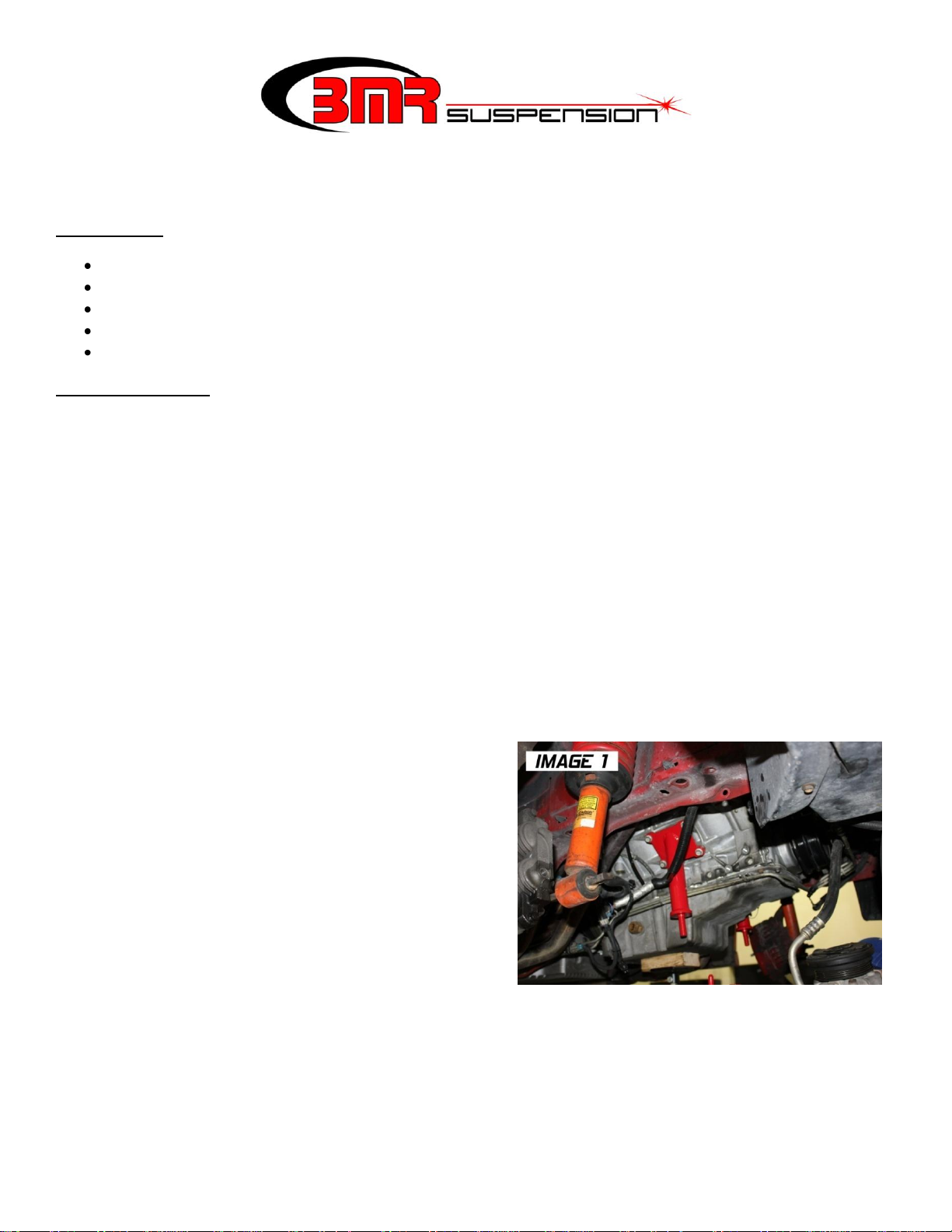
20. Bolt the BMR engine stands onto the motor as shown in IMAGE 1. Leave the bolts finger tight to allow some movement in
the stand. NOTE: The longer stand is intended for the drivers’ side. If header clearance is a problem, the engine stands may
be swapped to shift the motor ½” towards the other side.
CONTINUED

NOTE: For the manual rack version,
disregard the OE rack re-installation
steps and refer to the installation
instructions from the appropriate rack
conversion kit.
LS1 TUBULAR K-MEMBER INSTALLATION
PART # KM019 (CONTINUED)
21. If retaining the OE power rack and pinion, mount the rack to the K-member. Tighten the bolts to 80 ft/lbs.
22. Position one of the BMR polyurethane motor mount bushings onto each mount of the BMR K-member then lift the K-
member up into the car (IMAGE 2). This will require aligning multiple points while holding the weight of the K-member at
the same time so again, additional help will be required. Install and tighten all six (6) bolts.
23. Install the remaining two polyurethane motor mount
bushings on the bottom side of the motor stands along
with the provided washers and nuts. Lower the weight of
the motor onto the K-member then tighten the motor
stand nuts using a 15/16” socket. Tighten until the
polyurethane bushings just start to bulge. When
assembled correctly, the motor mount bushings should
look like IMAGE 3.
24. Reinstall the alternator. Reinstall the serpentine belt.
25. Attach the steering shaft to the rack and pinion and
tighten the bolt. There is an additional 11mm bolt at the
top of the steering shaft that may also be loosened to
allow steering shaft length adjustment, if necessary.
26. Reconnect both power steering lines and tighten.
27. Insert all four A-arm mounting bolts. If vehicle must be driven to an alignment shop, roughly center all mounting points in
the adjustment slots and tighten all four (4) bolts. If vehicle is at an alignment shop, leave loose until installation is complete.
28. Insert tie rods into spindles and tighten both castle nuts. Insert new cotter pins.
29. Reinstall starter.
30. Slightly bend the factory brake lines to conform to the new K-member and then zip-tie them into place.
31. Bend the ends of the brake lines in such a way that the mounting brackets line up with the brake line mounting tabs on the K-
member. You may also have to cut the OE brackets and re-bend them in order to fit properly. Insert bolts and tighten. Once
connected, the brake lines should look similar to IMAGE 4 below.
32. Re install sway bar.
33. Lower vehicle and reconnect battery.
34. Take vehicle to a reputable alignment shop to align the front suspension.
WWW.BMRSUSPENSION.COM
This product is an aftermarket accessory and not designed by the vehicles manufacturer for use on this vehicle. As such, buyer
assumes all risk of any damage caused to the vehicle/person during installation / use of this product.
 Loading...