

Please take a moment to verify contents of this package before proceeding with the installation. It is the sole responsibility of the
Purchaser to inventory these contents before vehicle disassembly. BMR Suspension will not be held responsible for additional
labor time, service lift charges, etc. that may occur due to missing items.
TUBULAR K-MEMBER INSTALLATION INSTRUCTIONS – 2005-2010 MUSTANG
Part #’s KM009, KM010, KM011
INSTALLATION:
1. Lift vehicle and support with stands positioned under the frame rails. Remove both front wheels/tires.
2. Using a 18mm deep socket, loosen both outer tie rod ends. Knock both tie rods loose from the spindles.
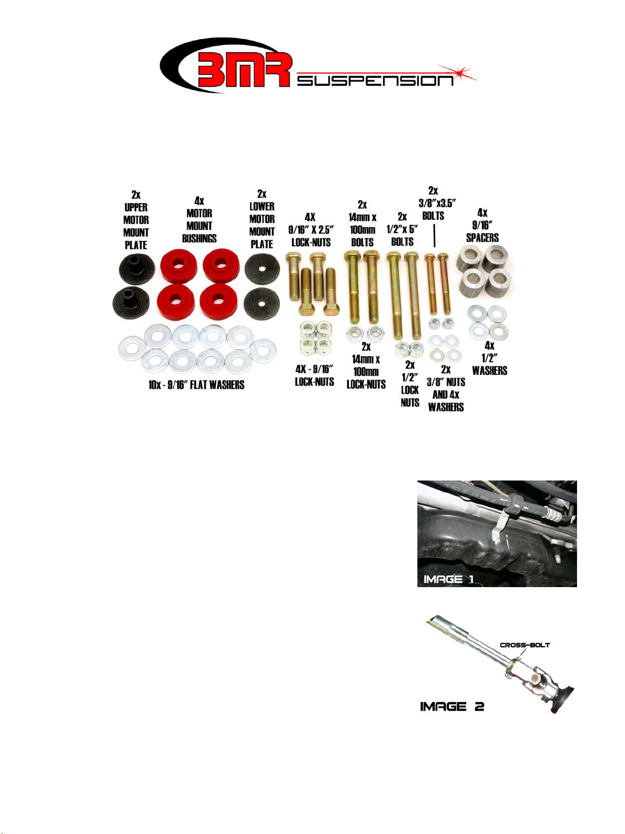
3. Remove the power steering line retainer located in the center of the rack.
This requires a 8mm wrench. See Image1.
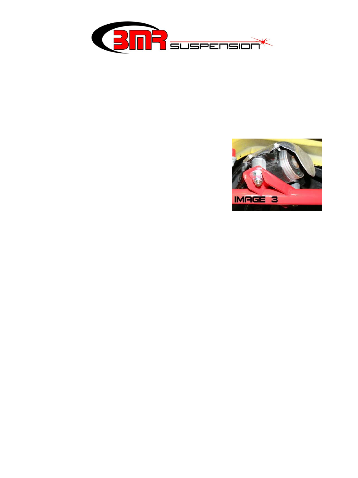
4. Using a 18mm socket, remove both rack mounting bolts. Mark a line on
the steering shaft at the front connection point to insure proper re-assembly
location. Remove the front steering shaft bolt using a 13mm socket or
wrench (See Image 2). Leave both power steering lines attached but move
the rack out of the way to gain access to the front A-arm bolts.
5. Remove all 4 rear A-arm bolts using a 21mm deep socket. Using a 18mm
socket, remove both front A-arm bolts.
6. Loosen and remove the A-arms’ ball joint cross-bolts using a 15mm wrench and a 18mm socket. Knock or pry
the ball joint loose from the spindle. NOTE: It is not possible to remove the A-arms until the K-member is
lowered.
7. Using a 15mm socket with an extra long extension, remove both motor
mount nuts from the top.
8. Support the motor from below with a block of wood on a hydraulic jack.
Lift motor slightly.
9. Using a 18mm socket, remove all 8 K-member bolts and lower the
K-member/A-arm assembly.
10. Insert one of the polyurethane motor mount bushings and sleeve into both motor mounts stands on the K-
member and lift the K-member up into place. Insert all 8 mounting bolts but do not tighten.
11. Line up the motor stands with the mounting bushings on the K-member. It may be necessary to shift the K-
member or the motor slightly to get the holes lined up. Once lined up, position the other polyurethane bushings
and supplied 2” washers on the bottom of the K-member mounting bracket and insert the supplied 3/8” bolt. The
bushings should “sandwich” the K- member mount when installed correctly. Tighten the bushing mounting bolts
to approximately 15 ft/lbs. using a 9/16” wrench and 9/16” socket.
12. Tighten all 8 K-member mounting bolts to 85 ft/lbs. using a 18mm socket. Lower jack and remove.
13. Install the A-arms using the supplied aluminum spacers and hardware (See Image 3). Tighten the front A-arm
bolts to 126 ft/lbs. using a 22mm wrench and socket. Tighten the rear to 110 ft/lbs. using a 13/16” wrench and a
7/8” socket.
14. Insert the ball joint into the spindle and insert the cross-bolt. Tighten to
40 ft/lbs. using a 15mm wrench and 18mm socket.
15. Using the supplied bolts and washers, mount the rack to the K-member.
When installing, verify that the steering shaft is positioned according to
the previous mark. Tighten both mounting bolts to 85 ft/lbs. using a ¾”
wrench and socket. Tighten steering shaft cross-bolt to 20 ft/lbs.
16. Mount both outer tie rods to the spindles and tighten to 85 ft/lbs. using a
18mm socket.
17. Re-install wheels/tires, double-check all mounting bolts and lower
vehicle.
18. Due to production tolerance, an alignment is recommended after this installation.
This product is an aftermarket accessory and not designed by the vehicles manufacturer for use on this vehicle. As
such, buyer assumes all risk of any damage caused to the vehicle/person during installation or use of this product.
 Loading...