

TUBULAR K-MEMBER AND A-ARM INSTALLATION INSTRUCTIONS
Part #’s: AA007, AA007K, AA008, KM006, KM006-1, KM007, KM007-1, KM008, KM008-1
While it is possible to perform this installation in the driveway, we consider it to be a moderate-to-difficult install. Professional
installation with a 4-post service lift is highly recommended.
• NOTE: This installation requires the removal of coil springs. Improper spring removal techniques can result in severe
injury or death. If you do not have experience in this area or feel uncomfortable with this installation, an experienced
technician is recommended.
• NOTE: If you are using our LS1 tubular K-member (Part #KM008, KM008-1) it is assumed that the original engine has
been previously removed and it is up to the installer to modify these instructions accordingly.
• NOTE: These particular K-members are not compatible with factory A-arms. Before proceeding with this installation, verify
that you have the correct part numbers for your application.
INSTALLATION:
1. Disconnect battery.
2. Lift vehicle and support with stands under the frame rails. Vehicle needs to be supported high enough to lower and install the
K-member. Remove both front tires.
3. Remove both cotter pins on the outer tie rod ends and loosen the castle nuts with a 19mm wrench. Knock the tie rod loose
and swing both tie rods out of the way.
4. Using a 13mm wrench and 13mm socket, remove both outer sway bar links and swing the sway bar down, out of the way.
5. Remove the cotter pin on the lower ball joint and loosen the castle nut using a 15/16” wrench. Loosen the nut until it is flu sh
with the top of the ball joint stud. DO NOT REMOVE NUT.
6. Using a pickle fork, break the ball joint loose from the spindle. Position a hydraulic jack under the A-arm and release tension
from the castle nut. Remove nut and carefully lower the A-arm, releasing spring tension slowly.
7. Using a large pry-bar, carefully pop the spring out of the A-arm pocket. Remove spring.
8. Repeat steps 5-7 on the other side.
9. Locate the brake lines in the outer wheel wells (See Image 1). Place a catch can and rags under the connection and loosen the
lines with a 12mm wrench. Using the same wrench, remove the two brake lines at the rear of the proportioning valve (See
Image 2). There is also one retainer that holds the rear brake line to the K-member. It is located directly below the master
cylinder and proportioning valve. Remove this retainer using a 10mm socket.
10. Using a 16mm wrench and an 18mm socket, remove both motor mount cross bolts.
11. Support the motor with a hydraulic jack or stand. Verify that the motor is stable before proceeding.
12. Remove all six K-member bolts using an 18mm socket. Using a 15mm socket, remove the front K-member triangular
supports that bolt to the frame rails.
13. Before lowering the K-member/A-arm assembly, make sure that all brake lines
have sufficient room to lower with the K-member. It may be necessary to bend
the brake lines slightly to simplify removing the K-member. Lower the Kmember/A-arm assembly slowly being careful not to damage any of the brake
lines.
14. Using a 14mm socket, remove the factory motor mount “clamshells” and install
the BMR/Moroso clamshells (See Image 3).
15. Before installing the BMR K-member, it is necessary to determine which A-
arms you will be using. If using the factory springs, it is necessary to use BMR
A-arms (PART #AA008) and BMR Upper Spring Pockets (PART #USP001). If converting to a coil-over spring setup, it is
necessary to use the BMR A-arm Kit (PART #AA007K) or equivalent.
PAGE 1
TUBULAR K-MEMBER AND A-ARM INSTALLATION INSTRUCTIONS (CONT.)
16. If installing traditional springs, please proceed to step 17 below. If installing the BMR coil-
over setup or equivalent, it is necessary to use the 4 provided aluminum shim washers when
installing the K-member. Position one washer under each of the front 4 main K-member bolts
and install the K-member. Use the factory bolts in all locations except the middle, use the
provided bolt in this location. Install all bolts but do not tighten. Proceed to step 19.
17. When installing traditional springs, it is necessary to also use BMR upper spring mounts (Part
#USP001). These mounts are particular to each side of the car and install in between the Kmember and the frame, essentially “sandwiching” the mount.
18. Position the mounts on top of the K-member in such a way that the spring seats angle outward.
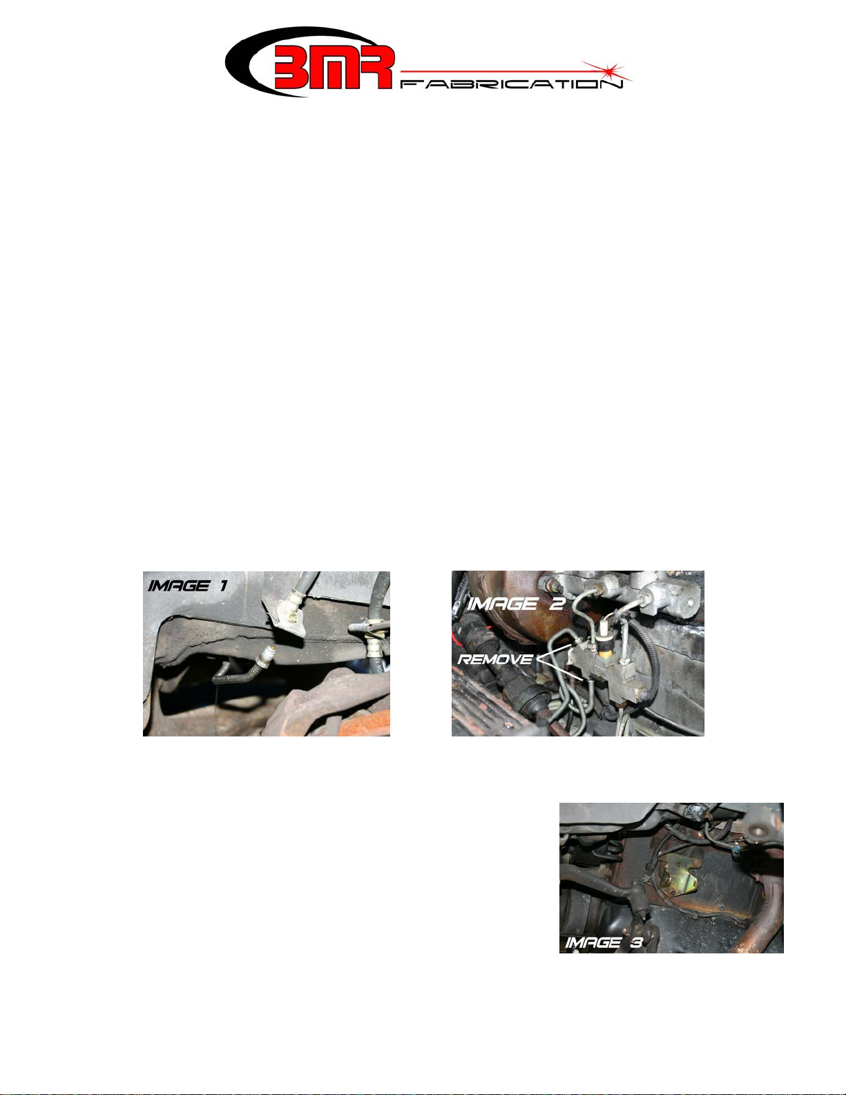
Install the K-member (See Image 4). Use the factory bolts in all locations except the middle,
use the provided bolt in this location. Install all bolts but do not tighten.
19. Line up the motor mount holes and insert the cross-bolts. It may be necessary to lift or lower
the motor in order to line up the mounting holes. Tighten both cross-bolts. Tighten all 6 Kmember bolts and torque to 130 ft/lbs.
A-ARM INSTALLATION FOR TRADITIONAL SPRINGS:
1. Lube the polyurethane bushings using the appropriate grease and install both A-
arms into the K-member. The sway bar mounts should point towards the front of
the car. Insert the provided mounting bolts and nuts but do not tighten.
2. Swing the A-arm up and position a hydraulic jack underneath the A-arm. Lift the
spring up and position it onto the upper spring pocket, allowing the bottom of the
spring to rest on the A-arm pocket. Using a long pry-bar, pry the spring until it
pops into position in the spring pocket. NOTE: It may be necessary to lift the A-
arm in order to get the spring pocket at the correct angle for the spring to pop into
place. With the spring in position, the end of the spring should butt up against the
stop in the spring cup.
3. Once the spring is seated properly in the cup, carefully lift the A-arm until the ball
joint seats into the spindle. Install the castle nut and tighten. Insert a new cotter
pin.
4. Repeat steps 1-3 for the other side.
5. Re-install the tie rod ends onto the spindles, tighten, and install new cotter pins.
6. Re-install the sway bar end links.
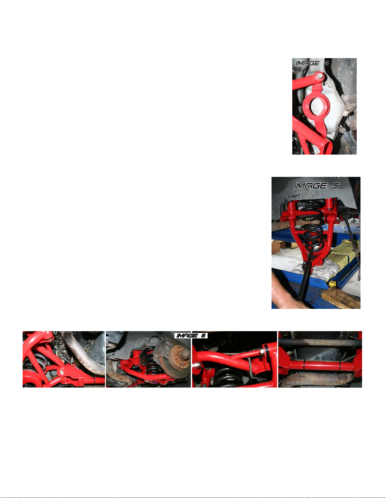
7. Remove the brake lines from the original K-member. With some slight
adjustment to the brake lines, they are compatible with the BMR K-member. Reinstall the lines, mimicking their position on the stock K-member. Use the supplied zip-ties to hold the brake lines in
place. See Image 6 below for brake line routing.
8. Tighten all fittings and bleed the system.
9. Re-install both front tires and lower the car.
10. Tighten the A-arm bolts with the car lowered. Grease all fittings in the A-arms until grease protrudes from the bushings.
11. Grease both lower ball joints until grease protrudes from the dust boot.
12. Double-check all bolts for tightness. Double check all brake lines for clearance.
13. Connect battery and have suspension aligned.
PAGE 2

TUBULAR K-MEMBER AND A-ARM INSTALLATION INSTRUCTIONS
A-ARM INSTALLATION FOR COIL-OVER SPRINGS:
1. Lube the polyurethane bushings using the appropriate grease and install both A-arms into the K-
member. Insert the provided mounting bolts and nuts but do not tighten.
2. Using a 13/16” socket, remove the main nut that holds the strut into the upper strut bushing.
Remove the entire strut and brake assembly.
3. Using a marker or scribe, mark the upper strut mounts in relation to the strut tower. This will
make it easier to get the alignment close when re-assembling the car. Using a 13mm socket,
remove the 3 nuts retaining the mount to the strut tower.
4. Position the BMR upper spring mount under the strut mount, re-insert the 3 bolt flange and re-
install the nuts. Do not tighten at this time.
5. Slide the BMR spring collar over the strut with the protruding tab facing downward. This tab
should be positioned inside the strut mounting flange (See Image 7) and is necessary to prevent
the collar from turning. NOTE: Some struts have a ring attached to the top of the strut that prevents the BMR spring collar
from fitting. In this case, it is necessary to replace the strut with a different unit or
remove the ring with a hammer and chisel (See Image 8).
6. With the collar is positioned on the strut, slide the BMR lower spring seat over the
collar as in Image 7. Install one set of needle bearings on the spring seat then slide the
spring over the collar.
7. Lift the entire assembly up until the strut shaft protrudes through the upper strut
bushing and the spring seats on the upper spring seat. Install the main nut to hold the
strut in place. Do not tighten yet.
8. Lift the A-arm up until the ball joint seats into the spindle. Install the castle nut and
tighten. Insert a new cotter pin.
9. Repeat steps 3-8 for the other side.
10. Re-install the tie rod ends onto the spindles, tighten, and install new cotter pins.
11. Re-install the sway bar end links.
12. Remove the brake lines from the original K-member. With some slight adjustment to the brake lines, they are compatible
with the BMR K-member. Re-install the lines, mimicking their position on the stock K-member. Use the supplied zip-ties to
hold the brake lines in place. See Image 6 on page 2 for brake line routing.
13. Tighten all fittings and bleed the system.
14. Using the supplied spanner wrench, adjust the lower spring seat to approximately the middle of the adjuster. Tighten the jam
nut against the collar.
15. Re-install both front tires and lower the car.
16. Tighten the A-arm bolts with the car lowered. Grease all fittings in the A-arms until grease protrudes from the bushings.
17. Grease both lower ball joints until grease protrudes from the dust boot.
18. Bounce the car a few times to allow the suspension to settle. If the car is too high or too low, remove tires and adjust the
spring height accordingly.
19. Double-check all bolts for tightness. Double check all brake lines for clearance.
20. Connect battery and have suspension aligned.
WWW.BMRFABRICATION.COM
This product is an aftermarket accessory and not designed by the vehicles manufacturer for use on this vehicle. As such, buyer
assumes all risk of any damage caused to the vehicle/person during installa tion or use of this product.
Page 3
(CONT.)
 Loading...