


1
COIL-OVER CONVERSION KIT INSTALLATION
CCK002 – 1964-1972 A-BODY
NOTE: Do not use bushing-type coil-overs with this setup, use only bearing-type coil-overs with ½” ID bearings.
INSTALLATION:
1. Safely support the vehicle. Remove the upper and lower A-arms and remaining front suspension to gain access to
the upper A-arm mount.
2. Using a cut-off wheel or plasma cutter, cut off the upper shock mount as shown in IMAGE 1 and 2. The
removed portion should look similar to the piece shown in IMAGE 3.
3. Smooth the remaining weld and contour the upper A-arm bracket using a sanding disc. The frame should appear
similar to IMAGE 4 when finished.
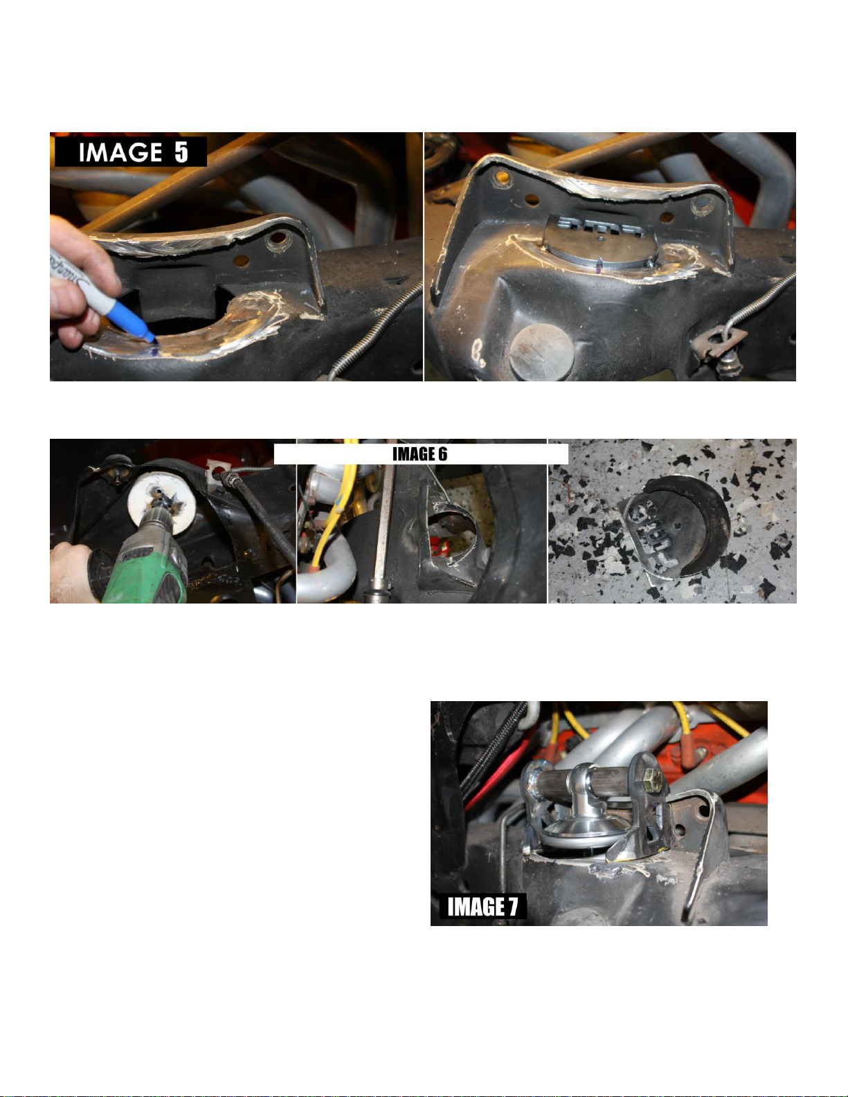
4. Once the upper shock mount is removed, it will expose a hole in the frame that extends into the spring pocket.
Find the center of the hole with a tape measure then mark it as shown in IMAGE 5 on the following page.
5. As shown in IMAGE 5, lay the drill template into the spring pocket and line up the relief in the template with the
previous mark.
6. Weld the drill template into place with 2-3 tack welds.
CONTINUED
2
COIL-OVER CONVERSION KIT INSTALLATION
CCK002 – 1964-1972 A-BODY
7. Chuck a 4” bi-metallic hole saw into a drill and cut out the top of the frame using the drill template to locate the
hole saw. The finished cut should look similar to IMAGE 6. De-bur the opening.
8. Properly positioning the upper shock perch requires an assembled coil-over and lower A-arm. In the images
shown below, we used a Viking coil-over with a lower shock T-bar. This allows the shock to bolt to the lower Aarm without any modifications. Most coil-over shocks can be ordered this way or you can buy T-bar adapters
from quality coil-over manufacturers such as AFCO, QA1, and Viking.
NOTE: Most coil-overs will have an upper mount that is somewhere between 1”- 1.5” wide. Your BMR coilover brackets will easily accommodate this range.
9. Bolt the lower A-arm in place then bolt the BMR
coil-over brackets to the upper mount of your coilover as shown in IMAGE 7. Position the coil-over
assembly into the frame and mount to the lower Aarm. Insure that the coil-over is centered in the
hole then position the coil-over brackets until they
fit with minimal weld gap as shown in IMAGE 7.
(NOTE: frame contours and OE welds vary slightly
and may require trimming of the bracket to get the
best fit. Also, varying widths of different brand
coil-overs will position the brackets differently,
requiring slight trimming to compensate.
10. Once the assembly is properly positioned and
centered in the opening, tack-weld the brackets into place.
CONTINUED
 Loading...