

Page 1

BATTERY MANAGEMENT TECHNOLOGY
THAT POWERS YOUR ADVENTURES.
BM PRO - 19 Henderson Road, Knoxeld 3180, Victoria, Australia
Phone +61 3 9763 0962 | Fax +61 3 9763 8789
Email [email protected] | Web www.teambmpro.com
OWNER’S MANUAL
Drifter
Page 2

2
CONTENTS
Introduction 3
Safety Precautions 3
Accessories 4
Other Required Items 5
About Drifter 5
Names and Functions of Parts 6
Operation 7
Description of Display Elements 7
Description of Switches and Buttons 8
USB Charger 9
Clock Setting 9
Advanced Conguration 10
Enabling Parameter Set-up Mode 10
New Battery Installation 12
Capacity Learning 12
Connectors 13
Installing the Drifter 14
Personnel 14
Installation Environment 14
Mounting 14
Battery Shunt Wiring 16
Water Tank Level Wiring 17
Servicing 22
Specications 22
After-sales Service 22
Repairs and After-sales Service 22
Warranty Terms and Conditions 23
Copyright © Setec 2014
Disclaimer
Setec makes no claim as to the accuracy or suitability of the information contained in this manual. Setec accepts no liability for
any loss or damage, which may occur as a result of improper or unsafe use of its products. Warranty is only valid if the unit has
not been modied by the customer and has not been misused.
Page 3
3
INTRODUCTION
SAFETY PRECAUTIONS
Please read the Safety Precautions carefully before installing the power supply. Be sure to
observe all precautions without fail.
After completing installation, conduct a trial operation to check for faults.
Failure to follow these instructions properly may result
in personal injury or loss of life.
Ensure that there is good ventilation from the battery area.
This appliance is not intended for use by young children or inrm persons
without supervision. Young children should be supervised to ensure that they
do not play with the appliance.
Batteries are electrically alive at all times and must be treated with extreme
caution. They can supply high short circuit currents, even if they appear
damaged.
Take care that dropping or touching of metal objects onto the battery cell
does not cause short circuits.
Remove any personal metal adornment such as a chain, watch or ring, which
could cause short circuits and personal injury.
Failure to observe these instructions properly may
result in property damage or personal injury, which
may be serious depending on the circumstances.
Refer to the installation section before operating. Correct installation is
the most critical factor in ensuring the safe use of the product. If every
consideration of these instructions has been satised the product will be safe
to operate.
Ensure that cable connections to batteries have the correct polarity and are
protected against accidental short circuit.
Ensure that the shrouding supplied with the battery is tted to the terminals.
Before servicing a battery, disconnect the power supply from the mains
supply.
Do not charge non-rechargeable batteries. Charging a non-rechargeable
battery may result in the battery catching re or possible explosion.
Do not allow water or other liquids to enter the installation area.
WARNING
CAUTION
Page 4
4
ACCESSORIES
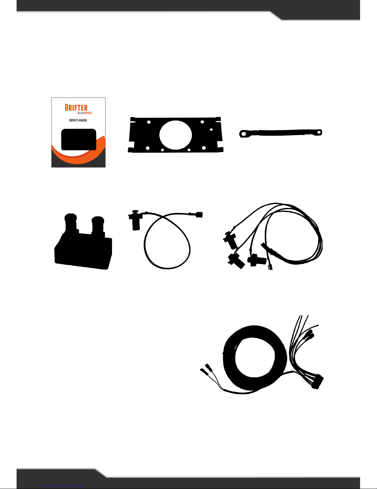
The following accessories are provided with the retail pack for this product.
Manual
Mounting bracket
Current shunt
Three-bung water level sensor
(Qty 2)
Battery neg cable
Single-bung water level sensor
(Qty 2)
Manual
Mounting bracket
Battery neg cable
OWNER’S MANUAL
Drifter
Manual
Current shunt
Mounting bracket
Single-bung water level sensor
(x2)
Battery shunt cable 9m
Three-bung water level sensor
(x2)
Remote shutdown cable 9m
Battery neg cable
Page 5

5
OTHER REQUIRED ITEMS
› Two sets of cables for connecting between the Drifter and the water tanks
› QC terminals or similar for the above cable.
ABOUT THE DRIFTER
Designed specically for caravan applications, the Drifter is a display unit that monitors water
tank levels and the 12 V battery charge state. Its backlit LCD presents information such as:
› Battery voltage
› Current owing in (charging)
› Current owing out (discharging)
› Estimated battery charge status and the estimated time to discharge
› Level indication of up to 4 water tanks including 1 waste water indicator
› Time (digital clock) with am/pm
› Water pump status
› Battery on/off status
Features also include:
› Back-light which can be set as a night light
› USB charger
› Water pump (on/off switch)
› Battery (on/off switch)
Page 6
6
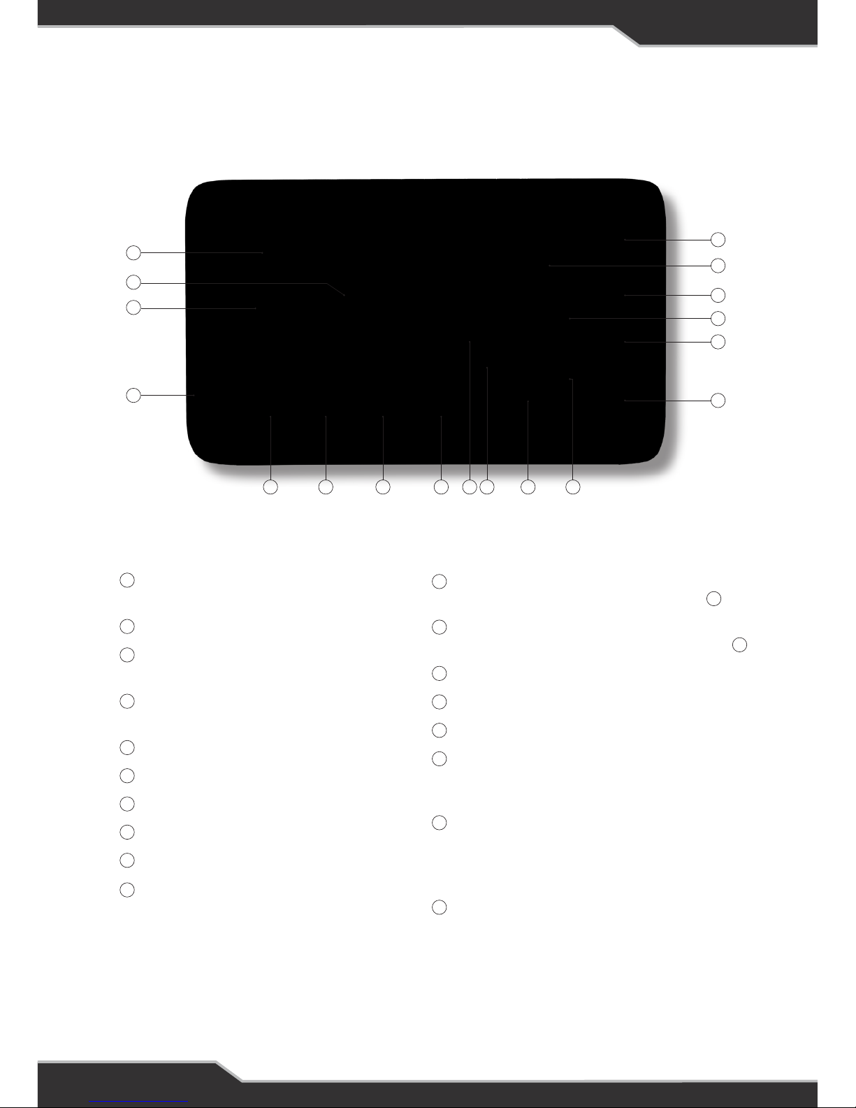
NAMES AND FUNCTION OF PARTS
Clock display
Current time in 12 hour mode
Battery charge state
Battery time remaining
while discharging at current discharge rate
USB charger
Generic 0.9 Amp USB charger
Water level in tank 1
Water level in tank 2
Water level in tank 3 (if tted)
Level in waste water tank (if tted)
Battery current
Warning annunciator
Displays if battery voltage is low
Switch status annunciator
Displays if battery is isolated by switch
Switch status annunciator
Displays if water pump is off due to switch
Battery voltage
Water pump switch
Back-light button
Home button
Home button is used for Setup functions and
parameter changes
Battery isolate switch
When paired with a compatible power supply,
this switch will isolate the battery fr
om the
loads
Ambient temperature
Ambient temperature in °C / °F
14
14
6
7
13
5
18
12
11
4
17
17
10
3
16
9
2
15
8
1
Figure 1: Names and functions
6 75
4
1039
2
1
8
14
13
18
12 11
17
16
15
Page 7

7
OPERATION
In normal power-on mode the unit displays the Home screen. The various display elements of
the Home screen are described below.
DESCRIPTION OF DISPLAY ELEMENTS
Clock
This displays the time of day in 12-hour mode with AM/PM indication. To set the clock, refer to
Clock Setting on page 9.
Temperature
This displays the ambient or room temperature. The temperature sensor is located in the
bottom left corner of the unit.
Time Remaining
This is the time remaining in the battery if it continues to discharge at the current rate.
› If the remaining time is 2 hours or less, the display shows the remaining time in minutes.
› If the remaining time is greater than 2 hours, the display shows the remaining time in hours.
› If the remaining time is greater than 199 hours, the display shows “>199 HRS”.
› If the battery is charging, the display is blank.
Charge State
This is a multi-segmented bar graph showing the state of charge of the battery. Above the bar
graph is displayed the word “CHARGING” or “DISCHARGING” according to the charging state
of the battery. .
Amps
This shows the charging current into the battery or the discharging current from the battery. To
determine if it is a charging or discharging current it is necessary to refer to the Charge State
indicator to the left of this eld.
Volts
This displays the battery voltage.
Fresh Water Tanks
These indicate the approximate water level in each of the tanks.
If a tank is not installed that tank indicator will always show empty (no level segments will be
shown).
When full, all level segments are shown.
When empty, the bottom level segment ashes and the other segments are not shown.
Note: If the pump switch is off, the water level displays are not updated; they continue to show
the levels from the last time the pump switch was on.
1
18
13
3
2
9
5 6 7
Page 8

8
Waste Water Tank
This indicates the approximate level in the waste water tank.
If the tank is not installed the indicator will always show full (all level segments will be shown).
When full, all level segments are shown and ashing.
When empty, only the bottom level segment is shown.
Note: If the pump switch is off, the display is not updated; it continues to show the level from
the last time the pump switch was on.
Battery Volts Low
This indicator shows when the battery voltage is at or below 11.0 Volts.
This is user settable, refer to Advanced Conguration section.
Battery Off
This indicator is displayed when switch is in the off position
Water Pump Off
This indicator is displayed when the water pump switch is in the off position.
DESCRIPTION OF SWITCHES AND BUTTONS
Battery Switch
Note: The Drifter is designed to interface with Setec power supplies. The functionality
described below assumes the Drifter has been correctly connected to such a power supply.
The Battery Switch is used to disconnect the battery from the loads.
In the off position the battery will not power the loads and “BATTERY OFF” is displayed.
In the on position no battery annunciator is shown and the battery will power the loads if no
mains power is connected.
Note: This switch also enables/disables the USB charging port
Home Button
The Home button is used
› in entering setup modes
› in changing settings
› to turn on the Back-light
Its usage is described in the relevant sections.
Back-light button
The Back-light button is primarily used to enable the back-light. It is also used in entering setup
modes and in changing settings.
10
11
17
16
15
17
11
14
12
8
Page 9

9
Back-light Functionality
Turn on back-light temporarily:
Press either the Home or Back-light button.
The back-light will automatically turn off after 30 seconds.
Turn on back-light Permanently:
With the back-light off, press and hold the Back-light button until the back-light blinks
(approximately three seconds).
Turn off back-light:
Press the Back-light button. This cancels both temporary and permanent back-light display.
Water Pump Switch
This switch controls power to the water pump.
In the up position the pump is off and the display shows “WATER PUMP OFF”
In the down position the pump is powered and the display does not show any water pump
annunciator.
USB CHARGER
A standard USB-style charger is integrated into the DRIFTER. Charge current is limited to 0.9A.
CLOCK SETTING
1. Ensure the display is in normal mode (not in any setting mode).
2. Press and hold the Home button for at least 5 seconds. The minute digits will start
ashing, the “TIME” annunciator will be displayed, and all other non-relevant display
segments are turned off.
3. Pressing the Home button will now toggle between setting the hour digits and minute
digits.
4. To increment the ashing digits, press the Back-light button.
5. To exit the Clock Setting mode, do not press any button for at least 15 seconds. When
the display returns to its normal appearance, it means setup mode has been exited.
14
4
12
Page 10

10
ADVANCED CONFIGURATION
These parameters are factory set.
Unless you are changing batteries or changing the number of water tanks, there is no
need to enter this mode.
ENABLING PARAMETER SETUP MODE
1. Ensure the display is in normal mode (not in any setting mode)
2. Press and hold the Home and Back-light buttons for at least 5 seconds.
When Parameter Setup Mode is entered:
› The “SETUP” annunciator is on (near the AM/PM indicators)
› The temperature digits show the parameter number
› The clock digits show the parameter value
› All other LCD segments are off.
3. Pressing the Home button displays the next parameter and its value. If the last parameter
is displayed, pressing the Home button displays the rst parameter. The available
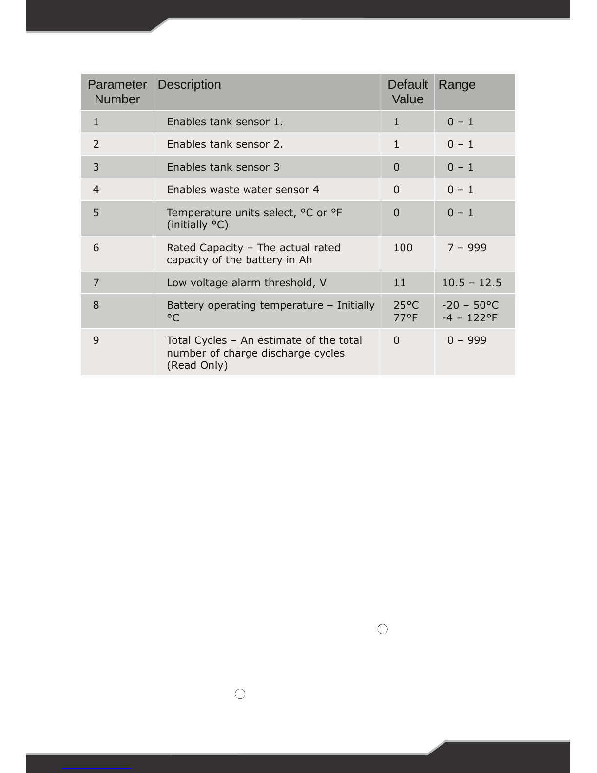
parameters are shown in Table 1: Setup Parameters.
4. To increment the parameter value, press the Back-light button.
› Incrementing past the maximum value causes the lowest value to be selected.
› For some parameters holding pressed the Back-Light button will force a fast or slow
increment of it’s value.
5. To exit the Parameter Setting mode, do not press any button for at least 15 seconds.
When the display returns to its normal appearance, it means setup mode has been exited.
Page 11
11
Parameter
Number
Description Default
Value
Range
1 Enables tank sensor 1. 1 0 – 1
2 Enables tank sensor 2. 1 0 – 1
3 Enables tank sensor 3 0 0 – 1
4 Enables waste water sensor 4 0 0 – 1
5 Temperature units select, °C or °F
(initially °C)
0 0 – 1
6 Rated Capacity – The actual rated
capacity of the battery in Ah
100 7 – 999
7 Low voltage alarm threshold, V 11 10.5 – 12.5
8 Battery operating temperature – Initially
°C
25°C
77°F
-20 – 50°C
-4 – 122°F
9 Total Cycles – An estimate of the total
number of charge discharge cycles
(Read Only)
0 0 – 999
Table 1: Setup Parameters
Tank Sensors
If a tank sensor is enabled but no tank sensor is connected, the tank level will be shown as
either full or empty, depending on whether the pump switch is on or off. By disabling the
sensor the tank level is always shown empty.
Temperature Units Select
This parameter sets the temperature units to either °C or °F. Setting it to a 1 will convert the
temperature to °F. Default units is °C.
Rated Capacity
This is the actual capacity of the battery in Amp-hours. When a new battery is tted, set this
to the nominal battery capacity (as marked on the battery); doing this will assist the software in
determining the actual capacity.
Low Voltage Alarm Threshold
This threshold sets the voltage at which the low voltage indicator starts blinking.
This is user settable and is used to indicate the desired low voltage.
Battery Operating Threshold
This is the typical operating temperature of the battery. This helps improve the accuracy of the
predicted time remaining readout . This can either be in °C or °F depending on parameter 5.
10
3
Page 12

12
NEW BATTERY INSTALLATION
The Drifter unit is a smart battery monitor in that it is able to learn the actual battery capacity
and thus provide more accurate “Time Remaining” feedback to the user. When an existing
battery is replaced by a new one, the capacity of the new one is likely to be much higher.
Fitting a new battery and doing nothing else will result in the “Time remaining” display initially
being quite inaccurate. As the battery is charged and discharged during normal use, the Drifter
unit will learn the battery capacity of the new battery.
CAPACITY LEARNING
This procedure should only be used when an existing battery has been replaced with a new
battery.
The general method the Drifter uses to learn the battery capacity is to measure the Amp-hours
required to atten a fully charged battery. The detailed process we recommend is as follows:
1. Enter the Setup Mode and view the Battery Capacity parameter. It should be set to the
manufacturer’s rated capacity for that battery. e.g. 100 Ah
2. Dis-connect all power to the Drifter for 5 seconds and then re-connect.
This allows for the Drifter to reset all counters for the new battery capacity therefore learning
the battery faster.
3. Charge the battery until the State of Charge reads 100%. Then further charge the battery for
24hrs.
4. Stop charging the battery. i.e. remove the 240V power.
5. Switch on loads (e.g. lights, TV etc.) until the battery is being discharged at 10% – 20%
capacity rate.
e.g. If you have a 100 Ah battery, 10% of 100 is 10, 20% of 100 is 20.
So, adjust the loads until the battery current reads between 10A and 20A.
Note: When discharged at the 20% rate, the discharge time will be approximately 5 hours.
At the 10% rate, the discharge time will be approximately 10 hours.
6. Wait until the battery voltage reaches 10.5 V.
If you are using the Drifter with a Setec power supply, this will not damage the battery. These
power supplies have a low voltage disconnect which protects the battery from discharging
to a damaging level. With these products the at battery state will be indicated by the battery
current dropping to zero and there being no power to lights etc.
If using a power supply without a low voltage cutout, you must monitor the battery voltage
and, when it reaches 10.5 V, turn off the loads.
When the loads are turned off, or when the low-voltage disconnect has been activated, the
battery voltage will increase slightly—this is normal.
7. Repeat steps 2 to 5 once or twice more.
8. The capacity-learning process is now complete.
The above process allows the Drifter to gure out what full and empty is and calculate the
actual capacity of the battery tted. If for any reason step 6 is not done, steps 1 to 5 MUST be
done to get a reasonable state of charge reading.
9
13
Page 13
13
CONNECTORS
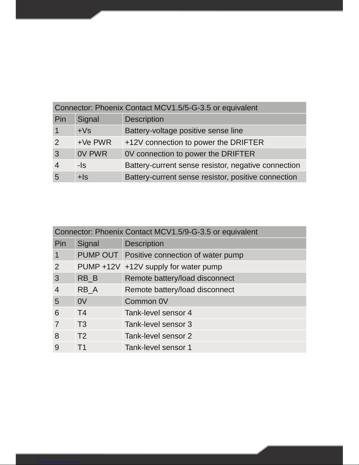
At the rear of the DRIFTER are two connectors. The connector type and pin functions are
dened in Tables 2 and 3 below.
dropping to zero and there being no power to lights etc.
If using a power supply without a low voltage cutout, you must monitor the
battery voltage and, when it reaches 10.5 V, turn off the loads.
When the loads are turned off, or when the low-voltage disconnect has been
activated, the battery voltage will increase slightly—this is normal.
Connector: Phoenix Contact MCV1.5/5-G-3.5 or equivalent
Pin Signal Description
1 +Vs Battery-voltage positive sense line
2 +Ve PWR +12V connection to power the DRIFTER
3 0V PWR 0V connection to power the DRIFTER
4 -Is Battery-current sense resistor, negative connection
5 +Is Battery-current sense resistor, positive connection
Table 2: 5-way Connector
Connector: Phoenix Contact MCV1.5/9-G-3.5 or equivalent
Pin Signal Description
1 PUMP OUT Positive connection of water pump
2 PUMP +12V +12V supply for water pump
3 RB_B Remote battery/load disconnect
4 RB_A Remote battery/load disconnect
5 0V Common 0V
6 T4 Tank-level sensor 4
7 T3 Tank-level sensor 3
8 T2 Tank-level sensor 2
9 T1 Tank-level sensor 1
13
Table 2: 5-way Connector
Table 3: 9-way Connector
Note: The digit ‘1’ is moulded into the rear of the Drifter case beside each connector, indicating
the location of pin 1.
dropping to zero and there being no power to lights etc.
If using a power supply without a low voltage cutout, you must monitor the
battery voltage and, when it reaches 10.5 V, turn off the loads.
When the loads are turned off, or when the low-voltage disconnect has been
activated, the battery voltage will increase slightly—this is normal.
Connector: Phoenix Contact MCV1.5/5-G-3.5 or equivalent
Pin Signal Description
1 +Vs Battery-voltage positive sense line
2 +Ve PWR +12V connection to power the DRIFTER
3 0V PWR 0V connection to power the DRIFTER
4 -Is Battery-current sense resistor, negative connection
5 +Is Battery-current sense resistor, positive connection
13
Page 14
14
INSTALLING THE DRIFTER
PERSONNEL
Installation is to be carried out only by suitably qualied personnel.
INSTALLATION ENVIRONMENT
The Drifter should be located indoors where it will not be subject to water or other liquid spills
or splashes.
In addition, for the temperature display to be usefully accurate, the Drifter should be located
where it will not be subject to hot or cold drafts, e.g. above a kettle is an undesirable location
from both a moisture and temperature perspective.
MOUNTING
The Drifter is supplied with a mounting bracket for attaching to the wall.
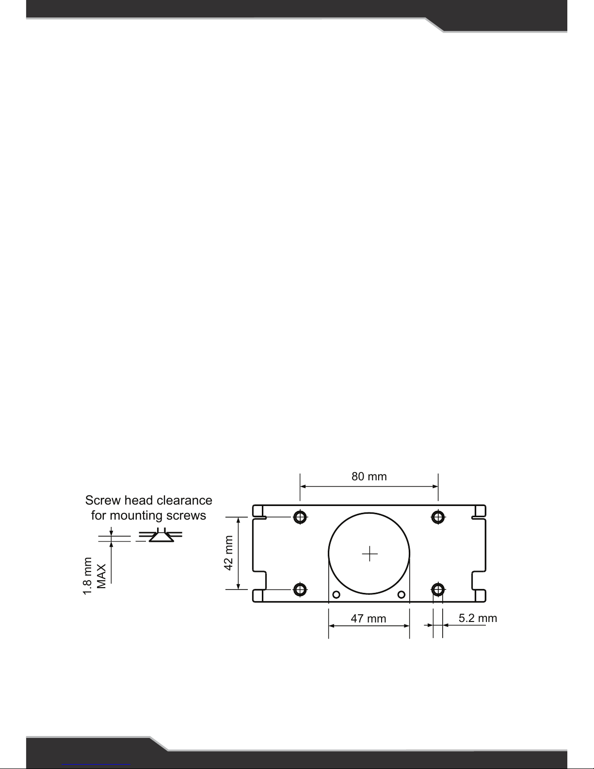
› Mounting screws should not be proud of the bracket by more than 1.8mm in order to
allow the Drifter to t on the bracket.
› The access hole to the wall cavity must be similarly sized to that in the bracket to provide
clearance for the connectors at the back of the Drifter.
› See Figure 1 for details.
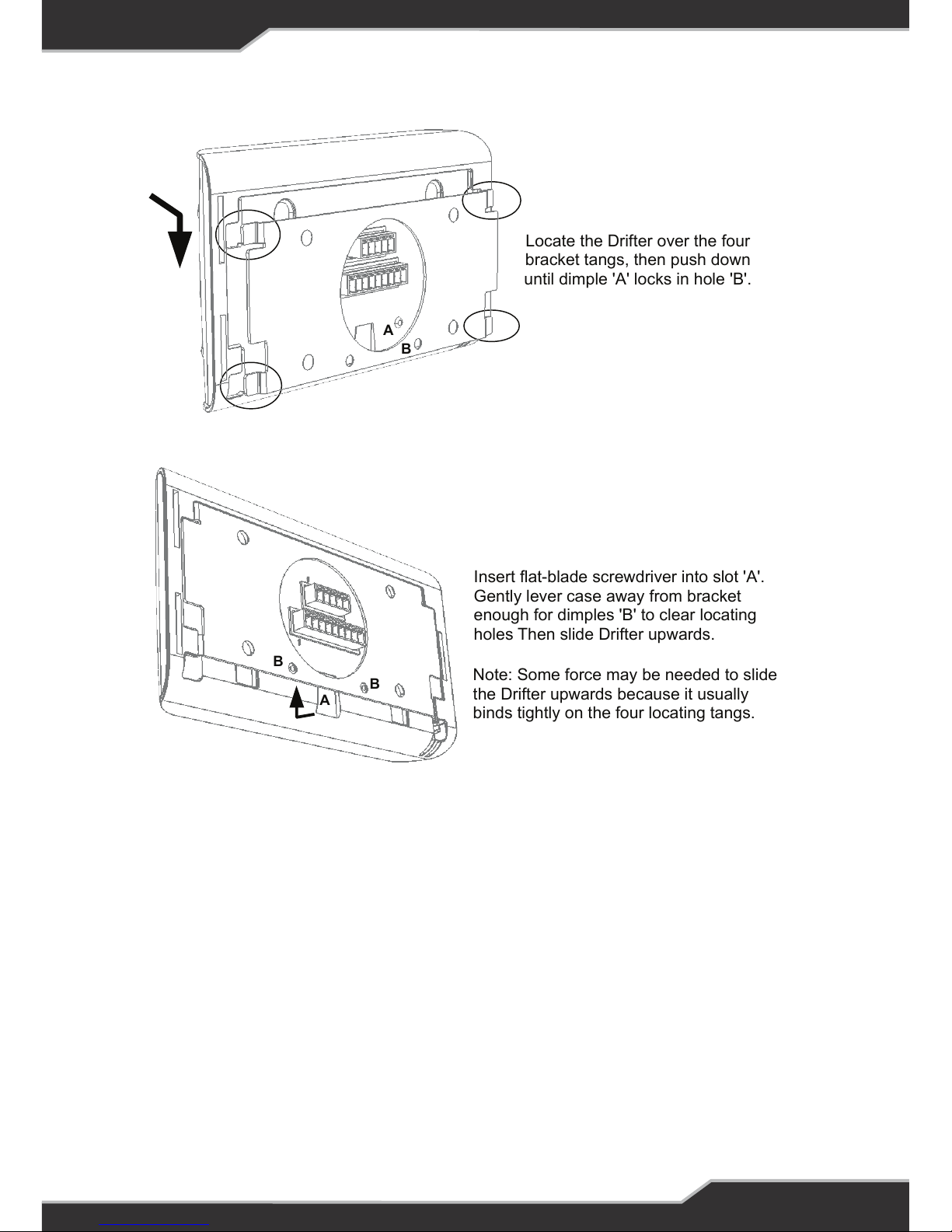
When wiring is completed and the connectors are mated to the unit, t the Drifter as detailed in
Figure 2.
If it is ever necessary to remove the Drifter from its mounting bracket, follow the instructions in
Figure 3.
80 mm
42 mm
47 mm
5.2 mm
1.8 mm
MAX
Screw head clearance
for mounting screws
Figure 1: Mounting Bracket Details
Page 15
15
Figure 1: Mounting Bracket Details
80 mm
42 mm
47 mm
5.2 mm
1.8 mm
MAX
Screw head clearance
for mounting screws
Locate the Drifter over the four
bracket tangs, then push down
until dimple 'A' locks in hole 'B'.
A
B
Figure 2: Fitting Drifter onto mounting bracket
Figure 1: Mounting Bracket Details
80 mm
42 mm
47 mm
5.2 mm
1.8 mm
MAX
Screw head clearance
for mounting screws
Figure 2: Fitting Drifter onto mounting bracket
Locate the Drifter over the four
bracket tangs, then push down
until dimple 'A' locks in hole 'B'.
A
B
Insert flat-blade screwdriver into slot 'A'.
Gently lever case away from bracket
enough for dimples 'B' to clear locating
holes Then slide Drifter upwards.
Note: Some force may be needed to slide
the Drifter upwards because it usually
binds tightly on the four locating tangs.
B
A
B
Figure 3: Removing Drifter from mounting bracket
Page 16
16
18
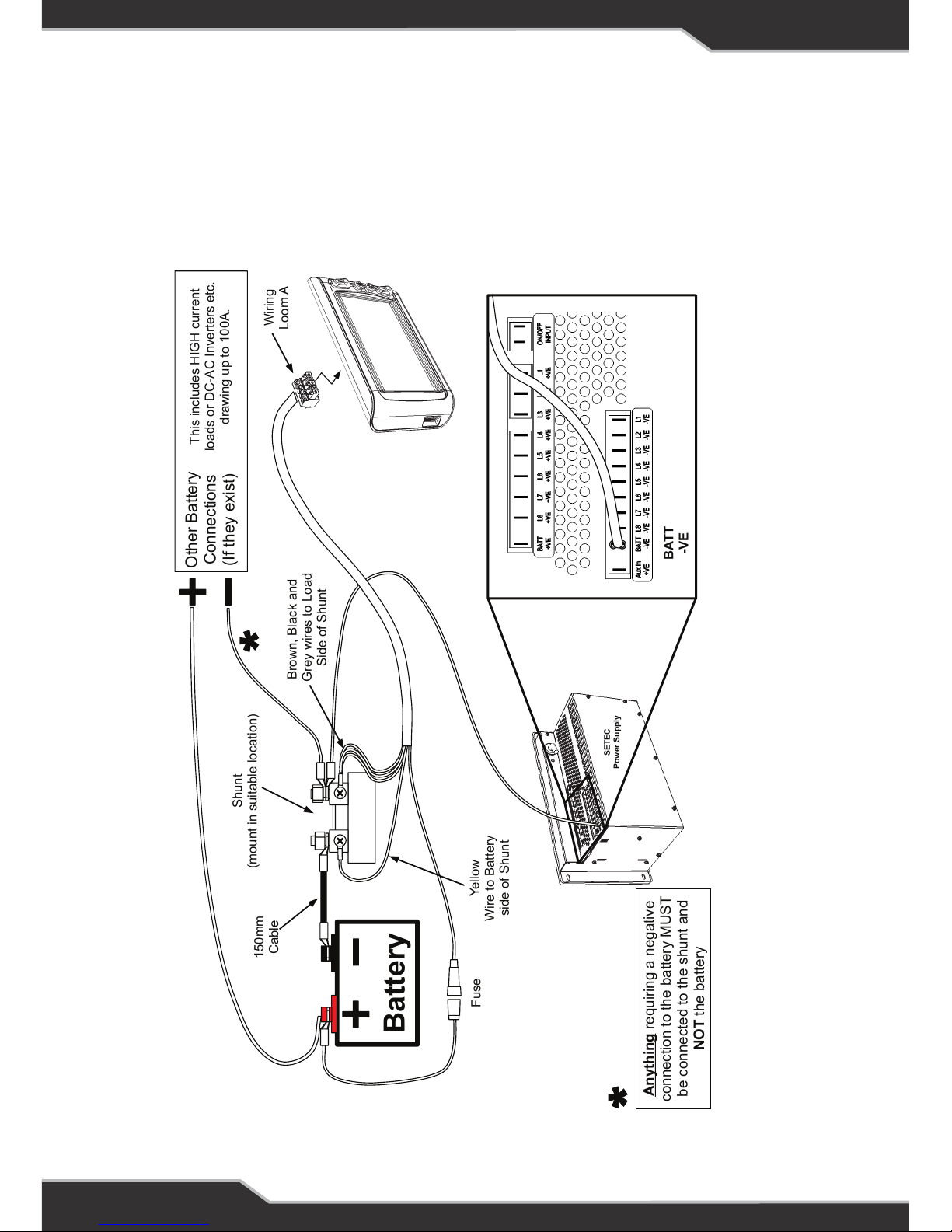
Figure 4: Battery Shunt Wiring
Battery
Brown, Black and
Grey wires to Load
Side of Shunt
Yellow
Wire to Battery
side of Shunt
Wiring
Loom A
Shunt
(mount in suitable location)
150mm
Cable
Fuse
BATT
-VE
SETEC
Power Supply
Anything requiring a negative
connection to the battery MUST
be connected to the shunt and
NOT the battery
Other Battery
Connections
(If they exist)
This includes HIGH current
loads or DC-AC Inverters etc.
drawing up to 100A.
Figure 4: Battery Shunt Wiring
BATTERY SHUNT WIRING
Important: To keep track of the battery capacity, this product needs to able to measure ALL
current into and out of the battery.
This is achieved by connecting a current-sensing shunt between the battery negative terminal
and all 0V connections. This connection arrangement is shown in Figure 4.
Page 17
17
WATER TANK LEVEL WIRING
1. Empty the water from the tank(s)
2. Choose a suitable side of the tank where the level-sensing bungs can be located.
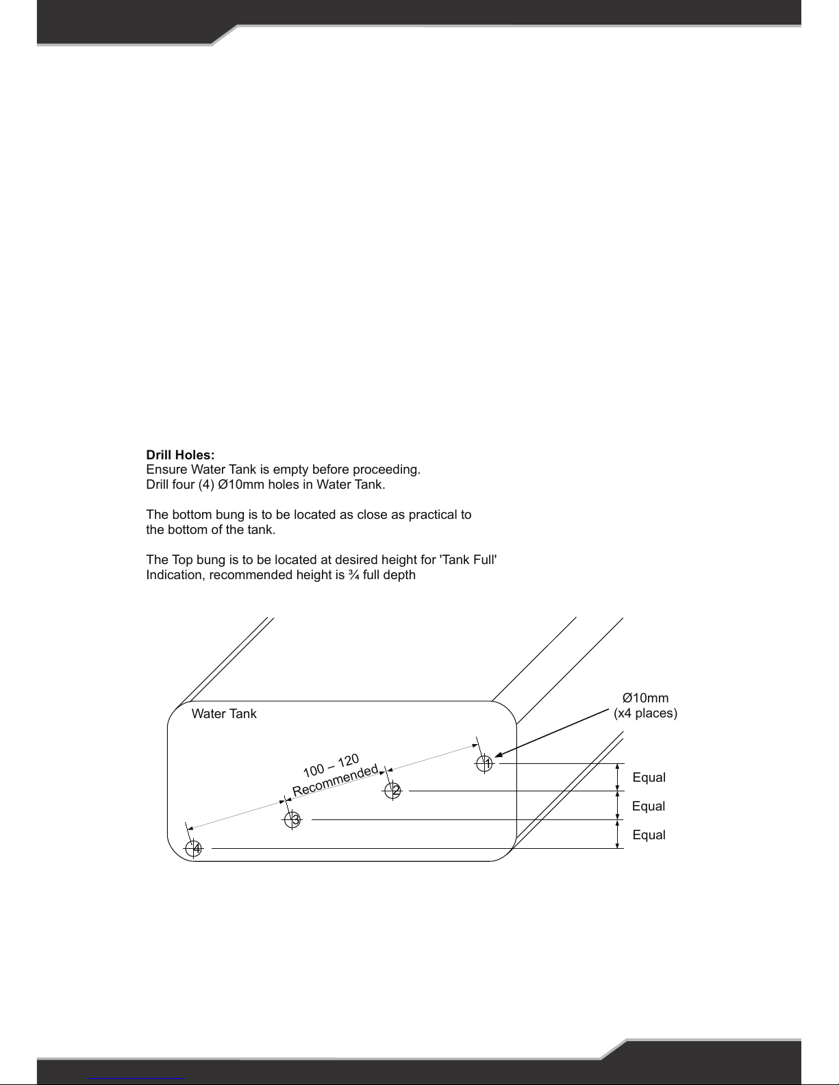
3. Drill the required holes as shown in Figure 5.
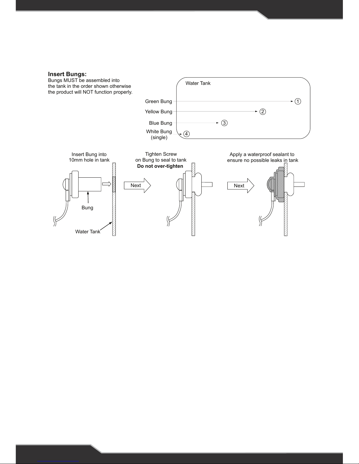
4. Fit the four bungs to the holes as detailed in Figure 6. Pay particular attention to which
bung goes into which hole, matching the wire colours as shown in Figure 6.
5. Connect the pump and remote on/off switch as detailed in Error: Reference source not
found (assuming Setec power supply is used). If used with other power supplies, connect
according to Error: Reference source not found.
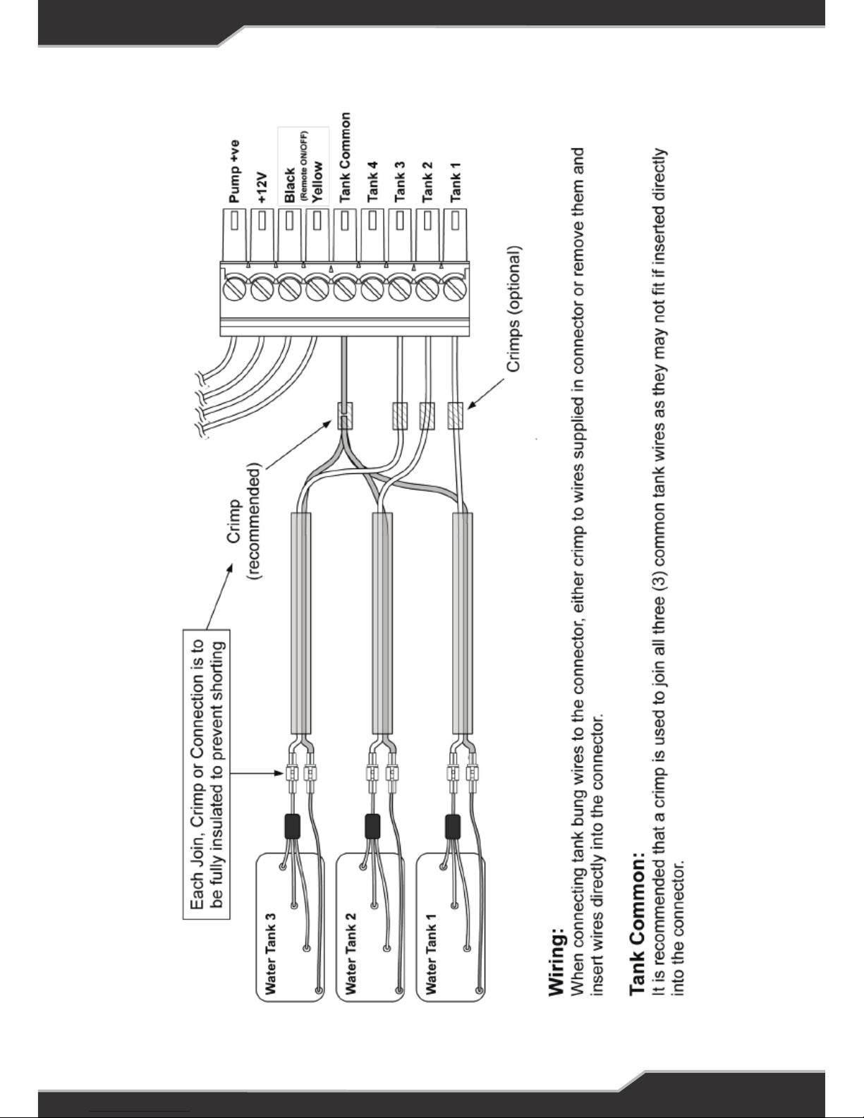
6. Connect the water-tank sensors as detailed in Error: Reference source not found.
7. Fill the tank(s) and check for water leaks around the bungs. Reseal as necessary.
8. Test operation of water level sensors, water pump switch, and remote on/off switch.
Drill Holes:
Ensure Water Tank is empty before proceeding.
Drill four (4) Ø10mm holes in Water Tank.
The bottom bung is to be located as close as practical to
the bottom of the tank.
The Top bung is to be located at desired height for 'Tank Full'
Indication, recommended height is ¾ full depth
Figure 5
Ø10mm
(x4 places)
4
1
2
3
1
0
0
–
12
0
R
e
c
om
m
en
d
e
d
Equal
Equal
Equal
Water Tank
Page 18
18
Water Tank
Next
Insert Bung into
10mm hole in tank
Tighten Screw
on Bung to seal to tank
Apply a waterproof sealant to
ensure no possible leaks in tank
Bung
Next
Green Bung
Yellow Bung
Blue Bung
White Bung
(single)
Insert Bungs:
Bungs MUST be assembled into
the tank in the order shown otherwise
the product will NOT function properly.
4
1
2
3
Water Tank
Do not over-tighten
Figure 6
Page 19

19
Figure 7: Tank, pump and remote switch connection for ST-III Series Power Supplies
22
Page 20

20
Figure 8: Tank and pump connection (for NON-SETEC ST-III Power Supply based installation)
23
Page 21
21
Figure 9: Tank Sensor Wiring
24
Page 22
22
Specication
Input Voltage 8 – 15 Vdc
Battery Drain < 3 mA (backlight off, no USB-attached device)
USB Output 0.9 A max, charger only
Ambient Temperature 0 ºC – 50 ºC
Size 149 Wide x 85 High x 22 Deep
SPECIFICATIONS
SERVICING
AFTER-SALES SERVICE
Do not disassemble, modify, or repair the unit.
Doing so may result in electric shocks or re.
REPAIRS AND AFTER-SALES SERVICE
Consult your Setec or BM PRO dealer.
WARNING
There are no internal user serviceable parts
Page 23

23
WARRANTY TERMS AND CONDITIONS
Registering your BM PRO product is an important step to ensure that you receive all of
the benets you are entitled to. Please visit www.teambmpro.com to complete the online
registration form for your new product today.
1. BM PRO goods come with guarantees that cannot be excluded under Australian Consumer
Law. You are entitled to a replacement or refund for major failure and for compensation for
any reasonably foreseeable loss or damage. You are entitled to have the goods repaired or
replaced if the goods fail to be of acceptable quality and the failure does not amount to a major
failure. The benets under this Warranty are in addition to your other rights and remedies under
a law in relation to the goods to which this Warranty relates (the Australian Consumer Law).
2. Setec, as the manufacturer of BM PRO goods warrants products against defects for a
period of two years, commencing from the original date of purchase. Proof of purchase is
required before you can make a claim under this warranty.
3. HOW TO PROTECT YOUR RIGHTS UNDER THIS WARRANTY: The DRIFTER is designed
to be installed by a suitably qualied installer. You or your installer should carefully inspect the
product before installation for any visible manufacturing defects. We accept no responsibility in
addition to our consumer guarantee obligations where a product has been installed incorrectly.
4. This warranty does not extend to product failures or defects caused by, or associated
with, but not limited to; failure to install or maintain correctly, unsuitable physical or operating
environment, accident, acts of God, hazard, misuse, unauthorised repair, modication or
alteration, natural disaster, corrosive environment, insect or vermin infestation and failure to
comply with any additional instructions supplied with the product.
5. Setec may seek reimbursement of any costs incurred by them when a product is found to
be in proper working order or damaged as a result of one or more of the warranty exclusions
mentioned in point 4 of this statement.
6. To enquire or make a claim under this warranty, please follow these steps:
a. Prior to returning a BM PRO product, please contact Setec on +61 3 9763 0962
to obtain a Return Material Authorisation (RMA) number
b. Package and send the product to: BM PRO Warranty Department,
19 Henderson Road, Knoxeld, VIC 3180.
Please mark RMA details on the outside of the packaging
c. Please ensure the package also includes: a copy of the proof of purchase, a detailed
description of the fault and your contact details including phone number and return
address
7. Setec will not be liable for any costs, charges or expenses incurred in the process of
returning a product in order to initiate a warranty claim
Manual Part #??????
Page 24
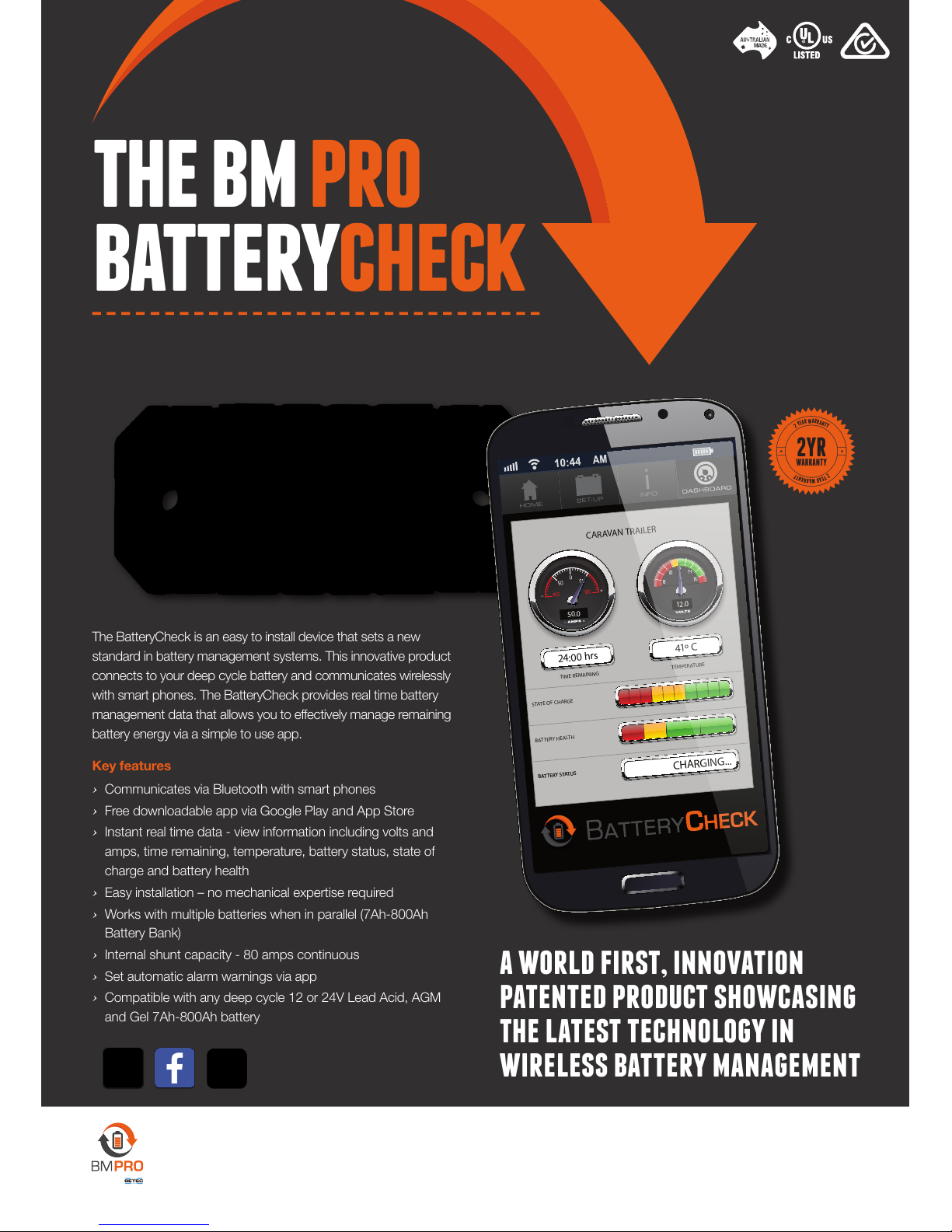
the bm pro
batterycheck
The BatteryCheck is an easy to install device that sets a new
standard in battery management systems. This innovative product
connects to your deep cycle battery and communicates wirelessly
with smart phones. The BatteryCheck provides real time battery
management data that allows you to effectively manage remaining
battery energy via a simple to use app.
Key features
› Communicates via Bluetooth with smart phones
› Free downloadable app via Google Play and App Store
› Instant real time data - view information including volts and
amps, time remaining, temperature, battery status, state of
charge and battery health
› Easy installation – no mechanical expertise required
› Works with multiple batteries when in parallel (7Ah-800Ah
Battery Bank)
› Internal shunt capacity - 80 amps continuous
› Set automatic alarm warnings via app
› Compatible with any deep cycle 12 or 24V Lead Acid, AGM
and Gel 7Ah-800Ah battery
a world first, innovation
patented product showcasing
the latest technology in
wireless battery management
STATE OF CHARGE
BATTERY HEALTH
TIME REMAINING
24:00 hrs
TEMPERATURE
41º C
BATTERY STATUSBATTERY STATUS
CHARGING...
CARAVAN TRAILER
12.0
+–
50.0
2
Y
E
A
R
W
A
R
R
A
N
T
Y
2
Y
E
A
R
W
A
R
R
A
N
T
Y
2YR
WARRANTY
SWITCH OFF. POWER UP.
BM PRO - 19 Henderson Road, Knoxeld 3180, Victoria, Australia
Phone +61 3 9763 0962 | Fax +61 3 9763 8789
Email [email protected] | Web www.teambmpro.com
BY
 Loading...