

Page 1
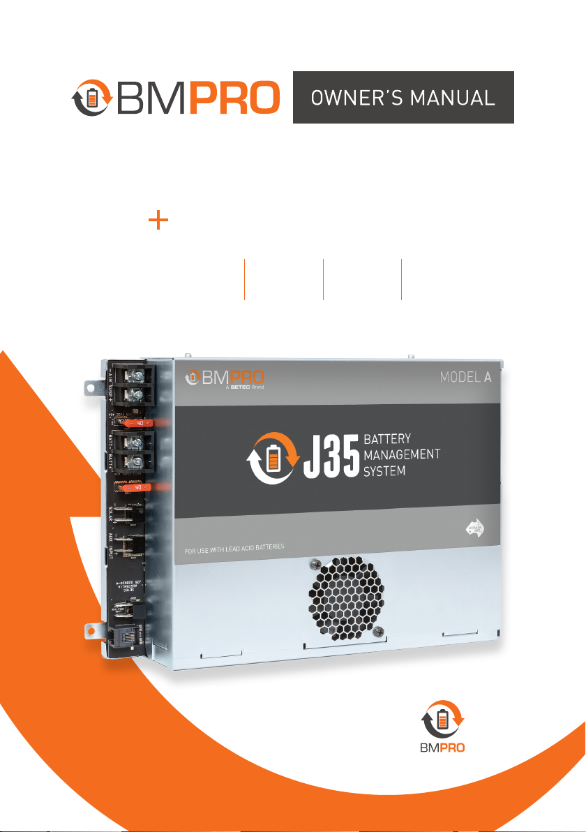
J35 ControlNode102
FOR MODELS
J35A J35B J35C J35D
TEAM
BMPRO
.COM
Page 2

POWERING YOUR ADVENTURES
Born by the innovative spirit of our parent company
Setec, with over 50 years’ experience in power
solutions, and design and manufacturing facilities in
Melbourne, we are the leading experts in RV power
management.
Inspired by the great Australian outdoors, we have
created a range of rugged, smart and reliable products
to power your adventures.
Our range of battery chargers, monitors and power
management systems for caravans gives you peace of
mind when you are on the road, so that you can relax in
even the most far-flung destinations, knowing that you
have control over your vehicle power.
To learn more about the BMPRO range of products,
please visit our website teambmpro.com
TEAM
BMPRO
.COM
2
Page 3
SAFETY PRECAUTIONS
Please read the Safety Precautions before installing or using the J35 and ControlNode102. Be sure to
observe all precautions without fail. Failure to observe these instructions properly may result in personal
damage, or personal injury which depending on the circumstances may be serious and cause loss of life.
Correct installation is the most critical factor in ensuring the safe use of the J35 and ControlNode102. If
every consideration of these instructions has been satisfied, the J35 and ControlNode102 will be safe to
operate.
This product is not intended for use by persons (including children) with reduced physical, sensor y or
mental capabilities, or lack of experience and knowledge, unless they have been given super vision or
instruction concerning the use of the appliance by a person responsible for their safety.
Children shall not play with this product. Cleaning and user maintenance should not be performed by
unsupervised children.
Ensure that the product is well ventilated and that if the product has a fan, the fan is not covered or
obstructed.
Metal conducts electricity. Take care not to drop or touch metal objects onto the battery terminals, which if
contacts the battery terminals, could cause short circuits and may lead to serious personal injury. Take care
and remove unwanted metal objects from the vicinity of the battery and J35. Remove any personal metal
adornment such as chain, watch or ring before handling the battery and J35.
Do not replace a damaged mains power cord. If the power cord is damaged, the product must be discarded.
Batteries are always electrically live and must be treated with extreme caution. They can supply high short
circuit currents, even if they appear damaged or undamaged.
Before servicing a battery, disconnect the power supply from all power sources.
Only charge battery types which are supported by this charger (see “Compatible Battery Types”)
Do not allow water or other liquids to enter the power supply area.
Do not drop or vigorously shake the product as this may cause damage. Do not shock the product, its
accessories or batteries as this may cause the product or battery to fail, catch fire or explode.
Stay away from magnetic equipment. Radiation may erase the information stored on this product causing it
to become inoperative.
Please note that your battery can only reach top performance level only after it has been fully charged and
discharged two or three times.
Electricity and water do not mix. Keep this product and your battery dr y and do not expose it to water or
water vapour. Do not operate this product or battery near any sort of liquid. Do not operate this product with
wet hands..
Do not use this product in environments that are excessively hot, cold, dusty or humid or where it will be
exposed to magnetic fields or long periods of sunshine. Such exposure may cause the product or your
battery to fail, catch fire or explode.
Only use this product with the supplied power cable and with batteries or accessories recommended in this
manual. Use of other batteries or accessories not recommended in this manual may cause damage to the
unit and will void the warranty.
The J35 and ControlNode102 is a high precision electronic product. It contains no user-serviceable
parts inside. Do not tr y to dismantle, modify or repair it yourself. Disassembly, service or repair by an
unauthorised person will void the warranty.
Before using this product, check that cable connections to the battery are of correct polarity. To protect
against accidental short circuit, ensure that the shrouding supplied with the batteries are always fitted to the
battery terminals.
Consult caravan dealer or qualified personnel before servicing your batter y.
Do not install this product in the same compar tment where flammable materials, such as petrol is stored.
Product specifications are subject to change and improve without notice.
3
Page 4
ABOUT THE J35
BMPRO’s range of J35 Battery Management Systems are specially designed to
be fitted in Jayco caravans.
The J35 operates from 240V AC mains power supply, towing vehicle auxiliary
and solar panels to simultaneously power caravan loads and charge the caravan
battery.
The J35 employs intelligent charging algorithms, ensuring optimal battery
health. Automatic battery preservation mode saves remaining battery power
until you’re ready and able to charge.
Download the JHub App to your mobile device and with the ControlNode102,
enjoy the freedom to monitor your caravan battery and operate caravan onboard
features, all from your own personal mobile device.
The J35 is available in a range of models to suite any RV and batter y
management needs.
FEATURE J35A J35B J35C J35D
Load Connections 7 14 14 14
Maximum Current Output 20A 35A 35A 35A
Maximum Charging Current 15A 15A 15A 30A
Solar Input
BYOD + JHub App
Lithium Compatible
Table 1: Comparison of features for the models in the J35 + ControlNode102 range
WHAT’S INCLUDED
Included with this product are:
9 J35 Battery Management System
9 ControlNode102
9 J35 + ControlNode102 Owner’s Manual
4
300W 450W 450W
Page 5

OPTIONAL ACCESSORIES
To get the most of your J35 it may be used with the following products
(sold separately) from the BMPRO range:
9 BC300 + CommLink External Shunt for integration of additional
accessories and high current loads such as inverters
9 JControl or JHub Battery Monitors
9 MiniBoost DC-to-DC charge-booster for RV applications
COMPATIBLE BATTERY T YPES
The J35 is rated to charge battery banks of up to 600Ah in capacity and of the
following battery types:
BAT TERY J35A J35B J35C J35D*
Lead Acid Valve-Regulated (VRL A)
Absorbed Glass Mat
(AGM)
Gel
Lithium LiFePO4
Table 2: Batteries compatible for use with the J35
* By default, the J35D is configured to charge lead acid batteries
The J35D is designed for use with LiFePO4 Lithium batteries only.
Do not connect other types of Lithium batteries to the J35D.
5
Page 6

MANUAL PART 032772
REV 6.0
Copyright © 2019
6
Designed by BMPRO, one of Australia’s leading power solution experts, the
BMPRO product range is proudly designed and manufactured in Melbourne,
Australia, and represent a high-quality product that will provide years of
service.
DISCLAIMER BMPRO accepts no liability for any loss or damage which may
occur from the improper or unsafe use of its products. Warranty is only valid
if the unit has not been modified or misused by the customer.
Page 7

CONTENTS
SAFETY PRECAUTIONS 3
ABOUT THE J35 4
What’s Included 4
Optional Accessories 5
Compatible Battery Types 5
J35 8
CONTROLNODE102 11
INSTALLATION INSTRUCTIONS 12
Replacing Batteries 12
Disconnecting a Battery from the J35 13
Connecting a Battery to the J35 13
Connecting Multiple Batteries 13
USING YOUR J35 14
Battery Charging and Management with the J35 14
Sleep Mode 15
Storage Mode 15
Using the J35 as a Power Supply (Battery-Less Operation) 16
Fault Protection 16
PAIRING WITH THE CONTROLNODE102 17
SERVICING, MAINTENANCE AND STORAGE 18
FAQS AND TROUBLESHOOTING 19
JHub App 19
Battery 19
Caravan Loads 20
APPENDICES 22
J35 Operational Status Indicator 22
Battery Charging Management Algorithm 23
Specifications 25
WARRANTY TERMS AND CONDITIONS 26
7
Page 8
J35
4
1
2
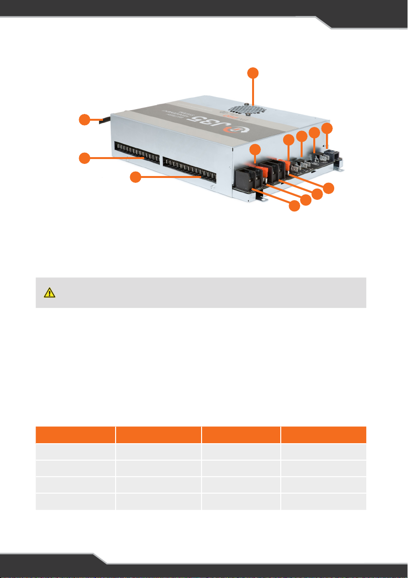
Figure 1: The J35
10
5
3
6
13
12
11
9
8
7
q MAINS CABLE
The J35 is pre-cabled with a permanent mains power supply cord. The AC mains
input is protected by a quick acting, high breaking capacity type fuse (rated 250V,
10A).
Do not replace a damaged power supply cord. If the power cord is damaged, the J35 must be
discarded. Ensure that the AC mains source always has an ear th terminal.
w LOAD TERMINAL BLOCK – COMMON NEGATIVE CONNECTION
Negative wire connection point for the caravan’s 12V loads.
e LOAD TERMINAL BLOCK – POSITIVE CONNECTION
Positive wire connection point for the caravan’s 12V loads.
To control loads from the JHub App, each load must be connected to the correct
terminal. Terminals are labeled according to their designated load output.
TERMINAL/LOAD CURRENT RATING TERMINAL/LOAD CURRENT RATING
1-Stereo 15A 5-Lights/Spare 10A
2-Spare 15A 6-Lights/Spare 10A
3-Pump 10A 7-Lights/Spare 10A
4-HWS 10A
Table 3: Designated terminal-load outputs for the load terminal block-positive connection, J35 Model
A.
8
Page 9
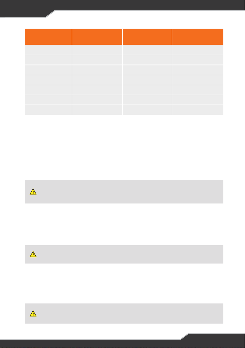
TERMINAL/
LOAD
1-Slide-Out 15A 8-12V Outlet 1 10A
2-Spare 2 15A 9-12V Outlet 2 10A
3-Water Pump 10A 10-Spare 10 10A
4-Hot Water 10A 11-Spare 11 10A
5-Lights 1 10A 12-Spare 12 15A
6-Lights 2 10A 13-AirSusp ECU 10A
7-Lights 3 10A 14-Tablet 5A
Table 4: Designated terminal-load outputs for the load terminal block-positive connection,
J35 Models B, C & D.
CURRENT RATING TERMINAL/LOAD CURRENT RATING
Each output is protected by an internal, electronic, auto-recoverable fuse. This
eliminates the need for the user to replace a blown fuse. If an electronic fuse is
activated, the LED Status Indicator on the J35 will flash a solid red. The J35 will
power off the faulty load and resume normal operation once the fault is fixed.
r FAN
Regulates the internal temperature of the J35.
To ensure continuous air-flow, the fan ventilation holes must never be blocked otherwise the
temperature of the J35 may rise and inhibit the optimal operation of the J35 and/or cause the
J35 to shut down. The J35 will automatically restar t once it has cooled to an acceptable level.
t LED STATUS INDICATOR
Indicates the operational status of the J35.
y AIR SUSPENSION OUTPUT (J35C / J35D)
Connection point to power the caravan’s air suspension.
The Air Suspension output is not controlled by the Load Isolation Switch circuitr y. Engaging
Load Isolation will not affect the operation of the caravan’s Air Suspension.
u AIR SUSPENSION FUSE (J35C / J35D)
40A automotive air suspension fuse.
i BATTERY CONNECTION TERMINAL
Screw connection for the caravan’s battery.
Do not connect the caravan battery’s negative terminal to caravan chassis or earth ground
point. Connecting the battery’s negative terminal to points other than the J35 negative
Battery Connection Terminal (Batt-) may cause the battery to overheat and/or overcharge.
9
Page 10

o BATTERY FUSE
40A automotive battery fuse.
a SOLAR INPUT (J35B /J35C / J35D)
The J35B supports the use of panels up to a total of 300W and the J35C & J35D,
450W. Input current to the solar regulator is limited to 20A (J35B, equivalent to
2x150W solar panels) or 27A (J35C & J35D, equivalent to 3x150W solar panels).
The solar input is unable to operate in Power Supply Mode, i.e. with no caravan
battery connected.
s AUXILIARY (AUX) INPUT
AUX input is designed for use with 12V DC power sources. The voltage of the DC
power source connected to the AUX input must not exceed 14.8V.
AUX will be available to charge the battery if the AUX voltage exceeds the battery
voltage by at least 0.5V.
Not all DC-DC chargers in the market used to boost auxiliary charging voltage from the
towing vehicle are compatible with the J35.
d LOAD ISOLATION SWITCH
To connect the caravan’s load isolation switch. This switch is used to enter Storage
Mode and power off all outputs (load terminal block and CAN bus) on the J35,
except for the Air Suspension output.
Battery charging is not affected by use of the load isolation switch.
As the caravan loads are no longer powered, activating the load isolation switch to
enter Storage Mode is a convenient way to save remaining power of your battery if
you are on the road and have limited ability to charge the battery. When charging,
Storage Mode ensures that all available charging current is dedicated to charging
your battery.
f CAN BUS COMMUNICATION
To connect to and power BMPRO accessories (BC300 + CommLink or
ControlNode102)
10
Page 11
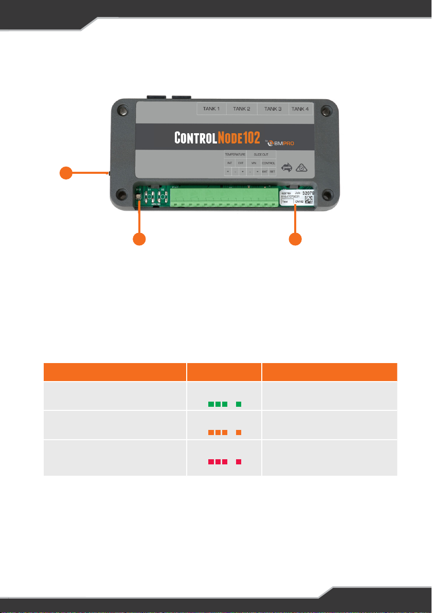
ControlNode102
1
Figure 2: The ControlNode102
3 2
q PAIRING BUTTON
Button to enable Bluetooth pairing between the ControlNode102 and the JHub
App on your own personal mobile device or JHub Tablet.
w LED STATUS INDICATOR
Indicates the operational/pairing status of the ControlNode102.
Table 5: ControlNode102 Operational Status and LED Flash Codes
Operational Status Flashing Status Note
ControlNode102 is ready to pair Green Flash 30 sec
ControlNode102 memory is full,
cannot pair to any new mobile devices
Clearing ControlNode102 memory* Red Flash 1 sec Memory will only be cleared if the
*After memory has been cleared, the ControlNode102 LED Status Indicator will immediately flash
green to enable pairing to a new mobile device.
Orange Flash 1 sec To pair to a new mobile device, clear
the memory of the ControlNode102
user presses and holds the Pairing
Button for 10 seconds.
e CONTROLNODE SERIAL NUMBER
Required to choose the correct device when pairing the ControlNode102
to the JHub App on your own personal mobile device or JHub Tablet.
11
Page 12
INSTALLATION INSTRUCTIONS
REPLACING BATTERIES
Before using a battery other than that which was installed at the caravan dealership,
consult with the battery manufacturer for a detailed description of the installation, uses and
maintenance of the battery. Verify that the type and capacity of the batter y or batteries used
are compatible for use with the J35.
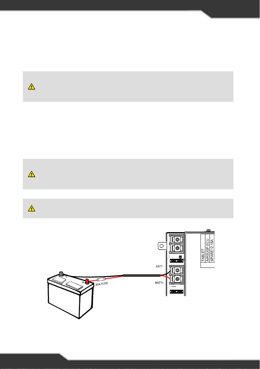
Figure 3 details connection of the caravan battery to the J35.
After fitting a new battery to the J35, make sure that it is configured in the JHub App.
Correctly configuring the battery capacity and profile will ensure that the J35 will
select the best charging parameters for the caravan battery in use, and the software
accurately estimates battery usage.
Sparks have the potential to cause an explosion should combustible gases be present. The
following procedures are designed to minimise the risk of spar k generation when connecting
or disconnecting the battery. The positive terminal of the battery must not be connected to
the chassis.
Do not install battery in the same compartment where flammable material, such as petrol, is
stored.
Figure 3: Wiring the caravan house battery to the J35. To protect against short-circuits
and reversed battery connections, install a 40A fuse, as close as possible to the
battery’s positive terminal.
12
Page 13
DISCONNECTING A BATTERY FROM THE J35
To disconnect a battery from the J35:
1. Power off all loads connected to the J35, the easiest way is with the switch
connected to the J35 Load Isolation input
2. Turn off and remove all power sources (mains/solar/AUX) to the J35
3. Disconnect the battery’s negative (black) terminal from the J35 Battconnection point
4. Disconnect the battery’s positive (red) terminal from the J35 Batt+
connection point
CONNECTING A BATTERY TO THE J35
To connect a battery to the J35:
1. Power off all loads connected to the J35, the easiest way is with the switch
connected to the J35 Load Isolation input
2. Turn off and remove all power sources (mains/solar/AUX) to the J35
3. Connect the battery’s positive (red) terminal to the J35 Batt+ connection
point
4. Connect the battery’s negative (black) terminal to the J35 Batt- connection
point
CONNECTING MULTIPLE BATTERIES
Before connecting multiple batteries in parallel to the J35, check that all batteries
are:
1. Of the same type, for example, deep cycle AGM battery
2. Of the same capacity, for example, 100Ah
3. By the same manufacturer
4. Fully charged
5. Of the same age-never use batteries that differ in age
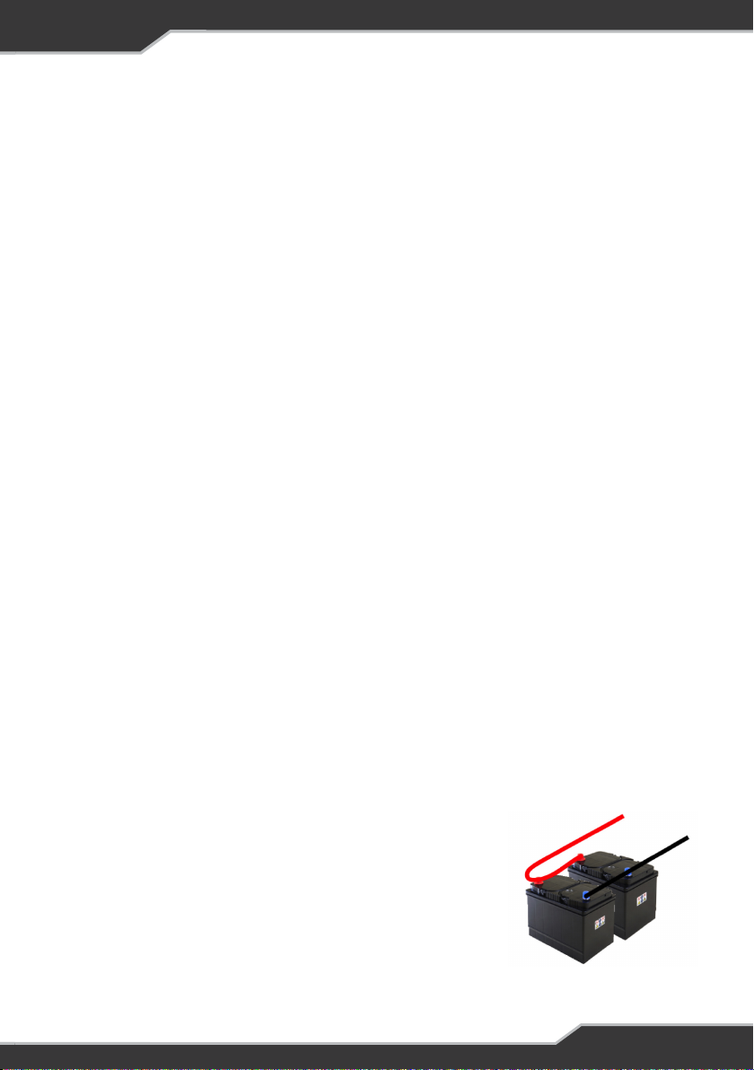
The recommended wiring for connecting multiple
batteries in parallel to the J35 is given in Figure 4.
Depending on system requirements, a qualified
auto-electrician may wire the batteries differently.
Figure 4: Recommended wiring for
connecting batteries in parallel.
13
Page 14

USING YOUR J35
BATTERY CHARGING AND MANAGEMENT WITH THE J35
Input Power Sources
The J35 may be powered from mains, AUX or solar inputs to provide battery
charging current and power to caravan loads.
If mains and one or more other sources are available to the J35, the J35 will be
powered exclusively by the mains source.
If both AUX and solar inputs are available and the mains is not, the J35 will draw
power from both the AUX and solar inputs. As full charge approaches, one of
these sources may dominate the other as appropriate.
Battery Charging
The J35 can simultaneously deliver up to 20A (J35A) or 35A (J35B, J35C, J35D)
to the caravan battery and loads from the mains input source, with a maximum
charging current of 15A. Maximum charging current is boosted to 30A in the J35D.
The maximum charging current will be reduced if loads are drawing significant
current and as the battery approaches full charge. To ensure that the caravan
battery is charged by the maximum charging current, switch off non-essential
loads.
When charging the battery from mains, the J35 applies a multi-stage charging
process.
For charging from AUX and/or solar sources, the J35 monitors the battery voltage
level and charges as needed.
Battery Health Preservation
The J35 preserves battery health by preventing the battery from excessive
discharge. The J35 will start a two-stage shutdown or Low Voltage Disconnect
(LVD), powering down all J35 outputs except for Air Suspension. This is to
conserve remaining battery capacity until the battery can be charged.
Air Suspension output is not affected by LVD and will remain operational throughout. The
remaining battery capacity will drain quickly if Air Suspension is engaged while the J35 is in
LVD.
14
Page 15
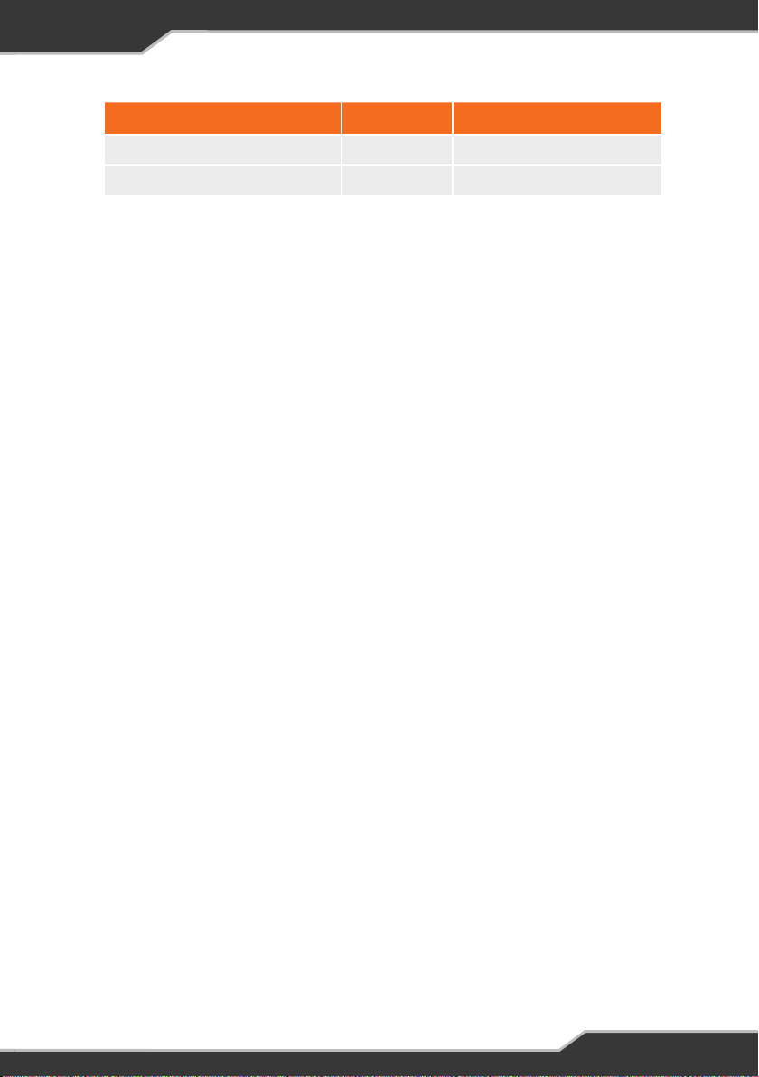
LVD MODE LEAD ACID LiFePO4 (J35D ONLY)
Sleep Mode 10.8V 12.0V
Storage Mode 10.5V 11.5V
Table 6: LVD Mode voltage thresholds
The J35 will enter the two stages of LVD, Sleep Mode and Storage Mode, when the
caravan’s battery voltage falls below the LVD thresholds.
SLEEP MODE
The J35 will provide power to the CAN bus. This allows you to continue to
monitor battery consumption from the battery monitor. However, power to the
load terminal block will be turned off and you will not be able to use your battery
monitor to power caravan loads.
To exit Sleep Mode, start battery charging. The J35 will exit Sleep Mode when the
battery is sufficiently charged. Upon exit of Sleep Mode, the J35 will automatically
return to its previous state of operation.
When in Sleep Mode you may temporarily turn on caravan loads by cycling the
caravan’s Load Isolation Switch. This feature allows you to retract slide-outs or
electric steps should you need to pack your caravan. This temporary switch on of
the caravan loads may also be done by pressing the Battery icon on your battery
monitor.
STORAGE MODE
Power to the CAN bus will now be turned off; meaning no communication or
power to the accessories connected to the J35 CAN bus. Please note, the JHub
Tablet (if in use) may run on its internal battery for some time.
To exit Storage Mode, start battery charging. The J35 will exit Storage Mode when
the battery is sufficiently charged. Upon exit of Storage Mode, the J35 will not
automatically return to its previous state of operation; caravan loads will need to
be powered on manually.
When in Storage Mode you may temporarily turn on caravan loads by cycling the
caravan’s Load Isolation Switch.
Heavily Discharged Batteries (Lead Acid)
The J35 will not charge heavily discharged lead acid batteries.
In normal use, and with the J35 battery health preservation, batteries should
never become heavily discharged.
15
Page 16

If your battery is heavily discharged, disconnect it from the J35 and charge with
a stand-alone charger. Reconnect the battery once the battery voltage has
recovered to normal levels.
Heavily Discharged Batteries (LiFePO4) (J35 Model D only)
The J35D can recover and charge a heavily discharged LiFePO4 battery. The
internal Battery Management System (BMS) of a LiFePO4 battery will turn off if it
detects that the battery is heavily discharged. The J35D will provide the voltage to
restart the LiFePO4 battery’s BMS and then commence charging of the LiFePO4
battery.
USING THE J35 AS A POWER SUPPLY (BATTERY-LESS OPERATION)
The J35 will act as a power supply if the following conditions are met:
1. A battery is not connected to the J35, and
2. The J35 is connected and powered from mains, or
3. The J35 is connected and powered from AUX input
Power Supply mode allows you to control and power your caravan’s loads directly
from mains or AUX without the need to connect the caravan battery. When
powered from the mains, the J35 provides an output voltage of 12.8V. When
powered from an AUX input, the output voltage will vary depending on the AUX
input voltage.
FAULT PROTECTION
Overload or Short Circuit Protection
If an overload or short circuit is detected, the affected output will shut down. The
J35 will automatically attempt to restart the output every 30 seconds until the
fault is removed.
Over-Voltage or High Internal Temperature Protection
If an over-voltage or high internal temperatures are detected the J35 will
automatically turn off. Once the over-voltage is rectified, or the internal
temperature drops to normal levels, the J35 may be restarted by cycling the mains
input on and off.
Reverse Battery Protection
The J35 Battery fuse and fuse fitted by your Jayco dealership at the battery
protects from accidentally connecting the battery to the J35 in reverse polarity.
16
Page 17

PAIRING WITH THE CONTROLNODE102
To pair the ControlNode102 to your own personal mobile device:
1. Make sure that the ControlNode102 is connected to the J35 and that the J35 is
powered on.
2. Turn on Bluetooth on your own personal device
3. Press the Pairing Button on the ControlNode102. The LED Status Indicator on
the ControlNode102 will flash green, indicating you have 30 seconds to pair
to the ControlNode102.
4. Launch the JHub App and press scan at the prompt.
5. The JHub App will now search for nearby ControlNode102 devices and a
pop-up window will appear listing ControlNode102 devices available for
connection.
6. Select the device with the number that corresponds to the last six digits of the
serial number of the ControlNode102 you wish to pair to.
For successful pairing, the LED Status Indicator on the ControlNode102 will turn
off and the Bluetooth Connectivity icon in the JHub App will turn blue.
A ControlNode102 can simultaneously pair to five mobile devices (including the JHub Tablet).
If the ControlNode102 is already paired to and in Bluetooth range with five mobile devices,
the LED Status Indicator on the ControlNode102 will flash orange for one second.
Press and hold the Pairing Button on the ControlNode102 for 10 seconds until the LED
flashes red. This will clear the ControlNode102 memor y of any connected devices. The
ControlNode102 will then automatically flash green to indicate that it’s ready to pair with a
new mobile device.
When you clear the memory on the ControlNode102, the Bluetooth connection to all mobile
devices paired to but not in Bluetooth range with the ControlNode102 will be lost. To use the
JHub App on these devices again, these devices will need to be re-paired.
17
Page 18

SERVICING, MAINTENANCE AND STORAGE
SERVICING
This J35 and ControlNode102 contains hazardous voltages and energy hazards
that may cause death or injury. Only qualified service personnel may service
theJ35 or ControlNode102. Except where stated in the following sections, do not
attempt to service the J35 or ControlNode102 yourself, OR dismantle, modify or
repair the J35 or ControlNode102 yourself; this will void your warranty. If your J35
or ControlNode102 requires servicing other than what is stated in this Owner’s
Manual, please consult your Jayco dealer for assistance.
SERVICEABLE FUSES
The J35 air suspension and battery fuse, if required, may be replaced by the
owner. To further protect from short circuits or overloading, the dealership will
have fitted a 40A fuse in-line with the caravan battery and a 30A fuse at the AUX
input.
If any fuse continues to fail, please contact your dealership for guidance.
MAINTENANCE
Use a dry or moist cotton cloth to lightly remove dust or dirt from the J35. Do not
use alcohol, thinners, benzene or any other chemical cleaner as these products
may degrade the housing surface. Do not allow any liquids to enter the housing.
Be sure to turn off all power sources to the J35 and disconnect the battery before
cleaning.
STORAGE
Once your adventure is over be sure to charge the caravan’s battery and power off
all loads connected to the J35. Use the switch connected to the J35 Load Isolation
input to enter Storage Mode and power off all loads.
When not in use, it is recommended that you recharge the caravan’s battery,
ideally monthly, or every three to six months. Regular recharge prevents the
battery from becoming heavily discharged-a condition which can significantly
shorten the battery’s lifespan.
18
Page 19

FAQS AND TROUBLESHOOTING
Need more help troubleshooting your J35 and ControlNode102? Contact our
customer service team online at teambmpro.com/technical-support or give us
a call on (03) 9763 0962.
JHUB APP
Is there a user guide for the JHub App?
You can access the JHub Mobile App User Guide from the settings menu of the
JHub App. If you would like to know more about the features of the JHub App,
download the JHub Tablet Owner’s Manual from the teambmpro website.
I have a ControlNode101, can I pair it to my own mobile device?
No, the ControlNode101 is only capable of pairing to the JHub Tablet.
I have a ControlNode101T (orange dot), can I pair it to my own mobile device?
No, the ControlNode101T (orange dot) is only capable of pairing to the JHub
Tablet.
BAT TERY
I’ve fitted a battery to the J35, but it’s not detected by my BMPRO battery
monitor?
Check the following:
1. Battery connections are tight and not loose or corroded
2. Battery polarity, red lead-positive, black lead-negative
3. The dealership fitted in-line fuse with the caravan battery is fitted and not
blown. Correct value is 40A.
4. Battery fuse on the J35 is fitted and not blown. Correct value is 40A.
19
Page 20

CARAVAN LOADS
I think one of my loads is not receiving power?
The load may be faulty, activating the protective electronic fuse and turning the
load off. If this is the case, the LED Status Indicator on the J35 will flash a solid
red.
Should you encounter any faulty loads, please contact your caravan dealership.
None of my loads appear to be powered but I can still use my battery monitor?
All loads will power down, but the battery monitor will still be in use if the J35 was
put into Sleep Mode. The J35 will be put into Sleep Mode if:
1. The user pressed the Battery icon on their battery monitor.
Check to see that Battery icon on your monitor has been pressed, thus turning
power off to the caravan loads.
2. The J35 has entered Sleep Mode and to conserve remaining battery voltage
will disable power to caravan loads.
Connect the J35 to a power source and begin battery charging.
None of my loads appear to be powered and the screen on my battery monitor
has turned off?
All loads, including any battery monitor in use with the J35 will power down if the
J35 was put into Storage Mode. The J35 will be put into Storage Mode if:
1. The user activated the switch connected to the J35 Load Isolation input. This
turns off power to all caravan loads and accessories connected to the J35
CAN bus such as your battery monitor.
Check that the switch has not been activated.
2. The J35 has entered Storage Mode and to conserve remaining battery voltage
will disable power to all caravan loads and accessories connected to the J35
CAN bus.
Connect the J35 to a power source and begin battery charging.
20
Page 21

Solar Output Appears to be Lower than Expected
If the battery is close to fully charged, the J35 will periodically turn off solar to
protect the batteries from overcharging. As a result, you may see less output on
your solar display.
The following tips will also make sure you are getting the most of your solar setup:
1. Make sure your solar panels are clean
For optimal performance of your solar panels, regularly clean them (when
cool) with warm, soapy water.
2. Consider the location of your caravan/RV
A shadow (for example from trees, buildings and even other accessories on
the roof of your caravan) across any part of the solar panel can reduce the
panel performance by up to 80%.
3. The time of day and time of year is important as well.
In some parts of the year (especially is southern parts of Australia) the sun will
never be directly overhead, so your solar output will be reduced-sometimes by
up to 50%.
21
Page 22
APPENDICES
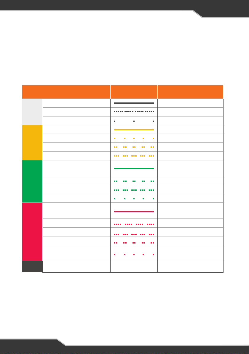
J35 OPERATIONAL STATUS INDICATOR
The following details the operational status of the J35, as shown by the coloured
flash of the LED Status Indicator on the J35.
Colour Code Flashing Status
Internal Error
Identify Device
White
Storage Mode
AC, Charging Normally
AC, Low Battery Voltage
Solar, Charging Normally
Yellow:
Charging
Aux, Charging Normally
AC, Battery OK or No
Battery
Solar, Battery OK
Aux, Batter y OK
Green: OK
Normal, No source present
One (or more) Output is
Overloaded
Critical Fault
Solar Fault
Battery Fault
Red: Error
Over Voltage Fault, or High
Temperature Fault
OFF J35 Powered Off Off
On, Solid
Flashes, 5 Times Quickly
Flashes Every 2min
On, Solid
Flashes, 1 Time
Flashes, 2 Times Quickly
Flashes, 3 Times Quickly
On, Solid
Flashes, 2 Times Quickly
Flashes, 3 Times Quickly
Flashes, 1 Time
On, Solid
Flashes, 4 Times Quickly
Flashes, 3 Times Quickly
Flashes, 2 Times Quickly
Flashes, 1 Time
22
Page 23
BATTERY CHARGING MANAGEMENT ALGORITHM
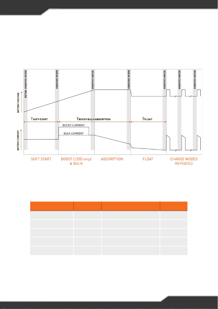
The following describes the Battery Charging Management Algorithm used by the
J35 when charging the caravan battery from a mains power source. The J35 will
operate as described when the caravan loads are connected directly to the J35
and not the caravan battery.
Figure 5: J35 Battery Charging Management Algorithm
Battery Capacity Soft Start Boost + Bulk-Absorption Float
≤ 100AH
150AH 6 Hours 7.5 Hours 6 Hours
200AH 6 Hours 10 Hours 6 Hours
250AH 6 Hours 12.5 Hours 6 Hours
≥ 300AH
Table 7: Timeout for each charging mode, based on battery capacity
6 Hours 5 Hours 6 Hours
6 Hours 15 Hours 6 Hours
23
Page 24
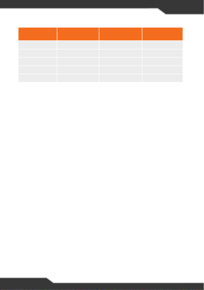
Charge Mode
Soft Star t 12.0 12.0 10
Boost (J35D only) 14.0 14.0 30
Bulk 14.4 14.6 15
Absorption 14.4 14.6 15
Float 13.6 13.6 10
Table 8: Battery charging management algorithm voltages and currents
Voltage Limit (V)
Lead Acid Batter y
Voltage Limit (V)
LifePO4 (J35D Only)
Current Limit (A)
The J35 intelligently controlled charging algorithm, automatically sets charging
parameters so that the caravan battery will maintain the best state of health. The
charging modes include:
SOFT START MODE
Charging current is maintained at 10A until the battery voltage reaches 12V or soft
start timeout (see table 7) occurs.
BOOST MODE
A feature of the J35D model only, current is boosted to 30A to bring the battery
voltage up to 14V, after which charging proceeds to Bulk Mode.
BULK MODE
Charging current is maintained at 15A until the battery reaches the Bulk voltage
(see table 8), after which charging proceeds to Absorption Mode
ABSORPTION MODE
Battery is charged at Absorption voltage until the current drops below 2A or
Boost-Bulk-Absorption timeout occurs.
FLOAT
Charging current is limited to 10A to keep the battery level topped up. Charging
will remain in Float for 6 hours. After Float timeout, the J35 will enter back into
Boost-Bulk-Absorption modes.
24
Page 25
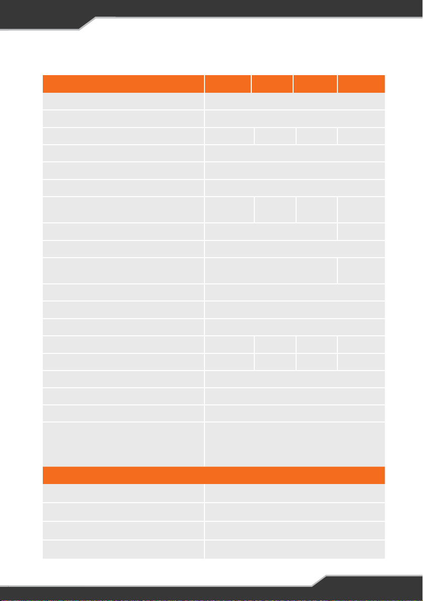
SPECIFICATIONS
J35 BATTERY MANAGEMENT SYSTEM J35A J35B J35C J35D
Input Voltage Range 240 VAC ± 10% (nominal), 50-60 Hz
Input Surge
Output Current (Load + Batter y Current) 20A 35A 35A 35A
Factory Set Voltage (Float Voltage) 13.65 V +/0.1 V
Output Ripple Voltage
Over Voltage Protection
Over Current Protection (Load + Battery
Current)
Battery Current Limit 15A 30A
Low Voltage Disconnect Lead Acid 10.5 ± 0.2V
Low Voltage Disconnect LiFePO4
Battery Drain (when in Storage Mode)
AC/DC Efficiency
Cooling Fan Thermally controlled
Solar Input Current
Solar Input Voltage – 15-25V 15-25V 15-25V
Ambient Temperature 0-50°C
Communication CAN Bus
20-25A 35-38A 35-38A 35-38A
– <20A <27A <27A
< 40A (cold start)
< 150 mV
< 18V
-
< 8mA
> 83 %
11.5 ±
0.2V
Weight 2 kg
Safety: IEC60335-2-29, IEC62109-1,UL458,
Standards
CSA C22.2 No.107-1, EMC: CISPR 14,
IEC61000-3-2, IEC61000-3-3 Approvals: RCM,
UL, cUL
CONTROLNODE102
Input Voltage 8-15 V DC
Battery Drain
Ambient Temperature 0–50ºC
Cable Length 0.5m
< 21 mA
25
Page 26

WARRANTY TERMS AND CONDITIONS
Registering your BMPRO product is an important step to ensure that you receive all of the benefits you
are entitled to. Please visit www.teambmpro.com to complete the online registration form for your new
product today.
1. BMPRO goods come with guarantees that cannot be excluded under Australian Consumer Law. You
are entitled to a replacement or refund for major failure and for compensation for any reasonably
foreseeable loss or damage. You are entitled to have the goods repaired or replaced if the goods fail
to be of acceptable quality and the failure does not amount to a major failure. The benefits under
this Warranty are in addition to your other rights and remedies under a law in relation to the goods to
which this Warranty relates (the Australian Consumer Law).
2. BMPRO warrants products against defects for a period of two years, commencing from the original
date of purchase. Proof of purchase is required before you can make a claim under this war ranty.
HOW TO PROTECT YOUR RIGHTS UNDER THIS WARR ANTY
3. The J35 and ControlNode102 are designed to be installed by a suitably qualified installer. You or
your installer should carefully inspect the product before installation for any visible manufacturing
defects. We accept no responsibility in addition to our consumer guarantee obligations where a
product has been installed incorrectly.
4. This warranty does not extend to product failures or defects caused by, or associated with, but not
limited to; failure to install or maintain correctly, unsuitable physical or operating environment,
accident, acts of God, hazard, misuse, unauthorised repair, modification or alteration, natural
disaster, corrosive environment, insect or vermin infestation and failure to comply with any
additional instructions supplied with the product.
5. BMPRO may seek reimbursement of any costs incurred by BMPRO when a product is found to be in
proper working order or damaged as a result of one or more of the warranty exclusions mentioned in
point 4 of this statement.
6. To enquire or make a claim under this warranty, please follow these steps:
a. Prior to returning a BMPRO product, please email [email protected] to obtain a Return
Material Authorisation (RMA) number.
b. Package and send the product to:
BMPRO Warranty Depar tment
19 Henderson Road
Knoxfield, VIC 3180
Please mark RMA details on the outside of the packaging.
c. Please ensure the package also includes: a copy of the proof of purchase, a detailed description
of the fault and your contact details including phone number and return address.
7. BMPRO will not be liable for any costs, charges or expenses incurred in the process of returning a
product in order to initiate a warranty claim.
26
Page 27

Page 28

POWERING YOUR ADVENTURES.
TEAM
BMPRO
.COM
BMPRO
teambmpro.com
 Loading...