

Page 1
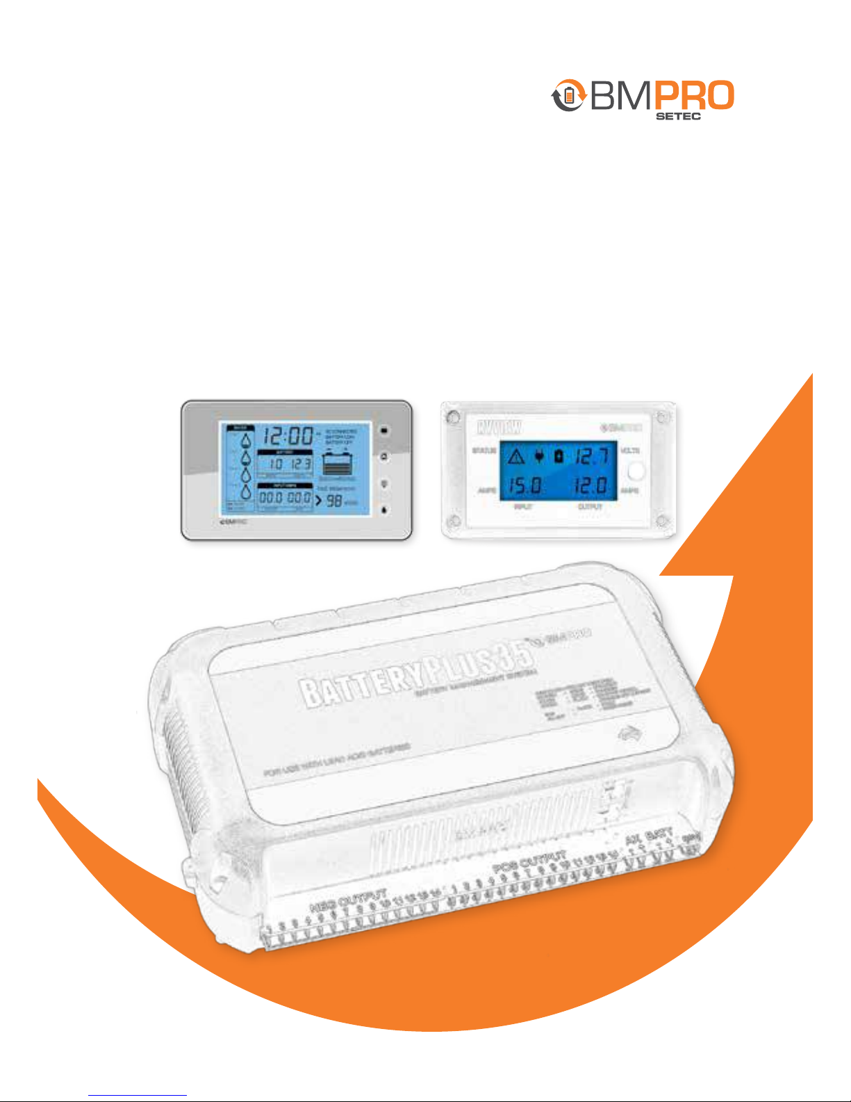
SYSTEM MANUAL
Trek + RVView
INCLUDING
BatteryPlus35
ABrand
www.teambmpro.com
Page 2
2
Accessories
Accessories provided with this product are:
System Manual
About the BatteryPlus35 Power Supply
The BatteryPlus35 is a smart charger with a distribution system which has been
designed for use in recreational vehicles. The unit operates from 100VAC to 240 VAC
and provides an isolated DC output at 35A maximum (derates to 32A at high ambient
temperature) for powering the loads, out of which a limited amount of current is
reserved for charging the caravan battery. All the necessary protection and operating
features for the load and battery are provided. BatteryPlus35 uses electronic fuses
to protect the wires connected to the loads.
A DC input is also provided to enable battery charging and powering of the load from
an external source, such as a car.
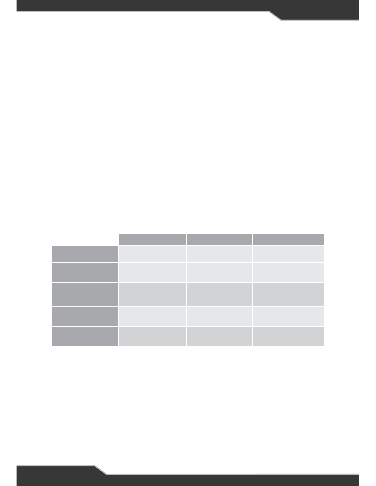
BatteryPlus35 has a solar input. Solar panels can be connected directly to
BatteryPlus35SR or BatteryPlus35HA, an external regulator must be installed for
BatteryPlus35PM, See table below.
MPPT- Maximum Power Point Tracking
The unit is fully enclosed ready for direct wall mounting. All connections are at the
base of unit providing convenient wiring and installation.
Note: When a BatteryPlus35PM is powered for the first time, the red LED will blink
for 30s, then resume normal LED pattern.
BatteryPlus35PM BatteryPlus35SR BatteryPlus35HA
Solar MPPT
No Yes Yes
Solar Input
External Regulator
required
Direct Solar Panel
connection
Direct Solar Panel
connection
Battery Chemistry
Lead-Acid Only Lead-Acid Only
Lead-Acid
LiFePO4
Absorption Charging
Current Max
20A 20A 30A
AX-Solar Blending
Yes Yes Yes
Page 3

3
Other Accessories that are sold separately:
Trek
Displays Battery voltage, Battery charging and discharging currents, Auxiliary and
solar currents, Battery charge status, Time remaining to discharge, Level indication
of up to 4 water tanks, Time am/pm, Water pump status and Battery on/off status. It
also features Back light which can be set as a night light, Button to control 2 water
pumps through BatteryPlus35, Button to disconnect the battery from the loads.
RVView
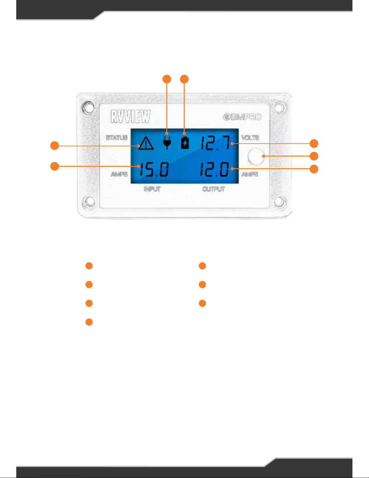
Display that shows System voltage, Input and output current, Battery charging and
discharging indicator, Power Source – Mains, Solar or Car, Warning indicator and
Battery charge status.
Page 4

4
BatteryPlus35
Accessories 2
About the BatteryPlus35 Power Supply 2
Safety Precautions 8
Name and Function of Parts 9
Installing BatteryPlus35 Power Supply 10
Personnel 10
Ventilation, Orientation, and Thermal Considerations 10
Mounting 11
Mains Cable 12
Wire Size 12
Load Connections 12
Caravan Battery Connection 13
AX (Auxiliary) DC Input Connection 13
Solar Connection 13
Remote Load-Isolator Switch Connection 15
Communication Bus Connection 15
Installing Controllable Pumps 15
Battery Connection/Disconnection Procedure 18
Batteries 19
CONTENTS
Page 5

5
Servicing 20
Functional Description 21
Functional Diagram 21
AC/DC Power Supply 22
Multiple Inputs and blending 22
Fault Protection 23
Fusing 23
Low Voltage Disconnect Modes 24
Battery Charging Management 25
AC Mains Charging 25
Solar Charging 25
AX Charging 26
Charging Profile 26
Charging time 26
System Status Indicator 28
Load output status indicators 28
Specifications 29
Page 6

6
CONTENTS
Trek
Introduction 31
Safety Precautions 31
Accessories 31
Other Required Items 31
About Trek 32
Glossary 32
Name and Function of Parts 33
Operation 34
On Power Up 34
Description of Display Elements 35
Description of Buttons 37
Setup Mode 38
Enabling Setup Mode 38
Setup Menu 38
Clock Menu 39
Water Tank Menu 40
Battery Capacity Menu 41
Battery Alarm Menu 41
LCD Backlight Menu 41
New Battery Installation 42
Connectors 42
Installing Trek 43
Servicing 46
Specifications 46
After-Sales Service 46
Appendix 1: Advanced Menu 47
Page 7

7
RVView
Introduction 49
Safety Precautions 49
Accessories 49
About RVView 49
Name and Function of Parts 51
Operation 52
Description Of Display Elements 52
Connectors 54
Servicing 54
Specifications 54
Repairs and After-Sales Service 54
Troubleshooting 55
RVView Installation Instructions 55
Manual Part #030333-B
The BMPRO BatteryPlus35 (BatteryPlus35), Trek and RVView are proudly Australian-made products manufactured in
Melbourne, Australia. Designed by Setec, one of Australia’s leading power solutions experts. They represent a high quality
product that will provide years of service.
Copyright © Setec 2017
Disclaimer
Setec accepts no liability for any loss or damage, which may occur as a result of improper or unsafe use of its products.
Warranty is only valid if the unit has not been modified or misused by the customer.
Important Note:
Trek is only designed to work in conjunction with the BatteryPlus35 supply/charger. It will not interact with other products.
Warranty Terms & Conditions 58
Page 8

8
SAFETY PRECAUTIONS
Failure to observe these instructions properly may result in property
damage or personal injury, which may be serious depending on the
circumstances.
Correct installation is the most critical factor in ensuring the safe use of the power supply.
If every consideration of these instructions has been satisfied the power supply will be safe
to operate.
Ensure that there is always good ventilation for the battery and the power supply.
Take care as dropping or touching of metal objects onto the battery terminals may cause
short circuits. Remove any personal metal adornment such as a chain, watch or ring, which
could cause short circuits and personal injury.
Batteries are electrically live at all times and must be treated with extreme caution. They can
supply high short circuit currents, even if they appear damaged or undamaged.
Before servicing a battery, disconnect the power supply from all power sources.
Do not attempt to charge non-rechargeable batteries. Charging a non-rechargeable battery
risks the battery catching fire or possible explosion.
Do not allow water or other liquids to enter the power supply area.
Do not drop or shake the product vigorously as this may cause damage to the product. Do not
shock the equipment, batteries and charger, as this may cause device or battery failure, fire
or explosion.
Stay away from magnetic equipment; radiation may erase information stored on the device.
Please note that the battery can only reach top performance level after it has been fully
charged and discharged two or three times.
Keep the device dry; do not expose it to water. Do not use it where it can fall into water (such
as near a pool, pond, bath etc.). Do not let the device, battery or charger come into contact
with water vapour or operate it with wet hands. Contact with water will cause the device to
short-circuit, corrode or cause electric shock.
Do not use this product where it is excessively hot, cold, dusty or humid, or where it is
exposed to strong magnetic fields or long periods of sunshine. Such exposure may cause
device or battery failure, fire or explosion.
Only use the device with the battery and cable supplied. Use of other accessories not
recommended in this manual may cause damage to the unit and will void the warranty.
Clean the housing of the device lightly with a dry or moist cotton cloth. Do not use alcohol,
thinners, benzene or any other chemical cleaner.
This device is a high precision electronic product. It contains no user-serviceable parts
inside. Do not try to dismantle, modify or repair it yourself. Disassembly by unauthorised
persons will void the warranty.
Specifications are subject to change and improvement without notice.
CAUTION
Please read the Safety Precautions carefully before installing the power supply.
Be sure to observe all precautions without fail.
Page 9
9
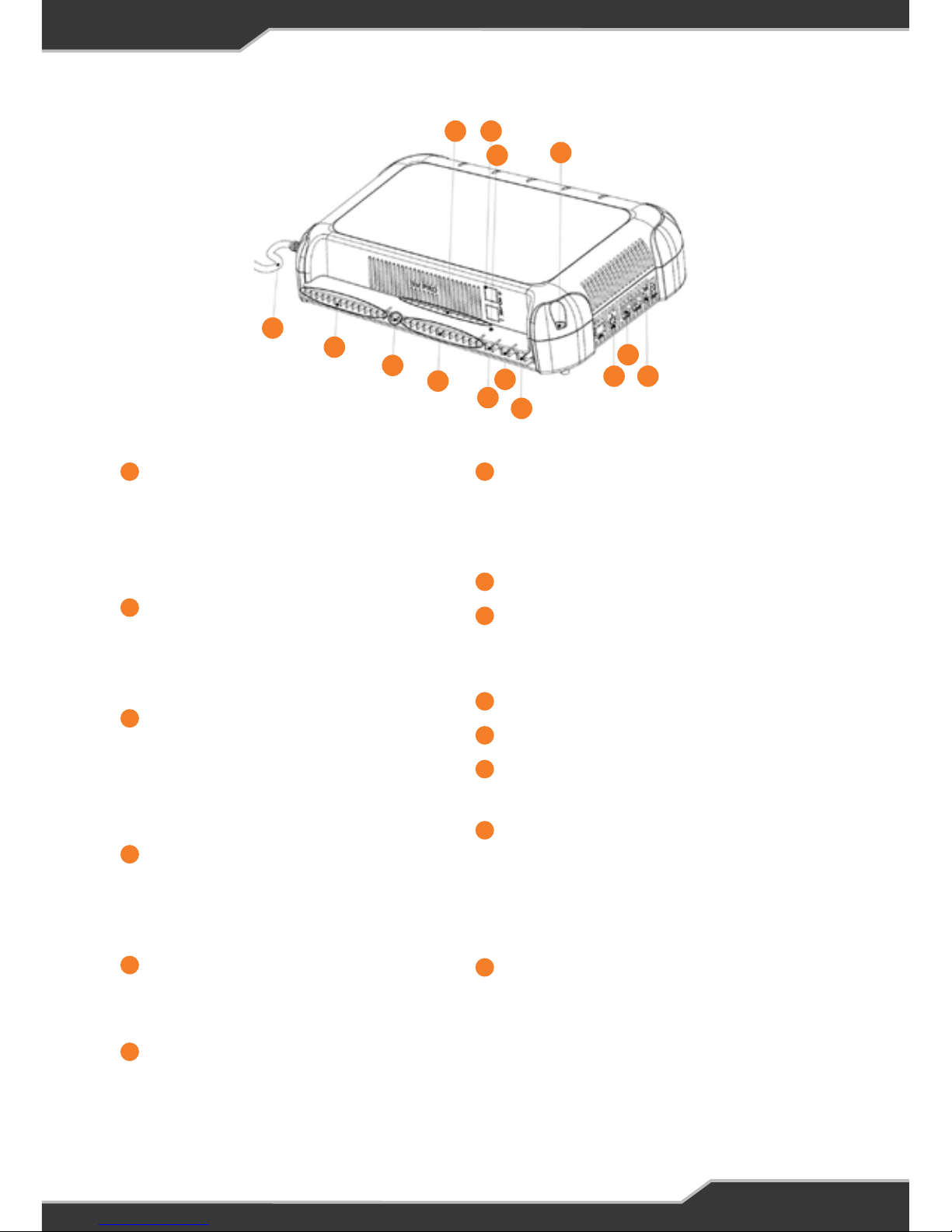
1
2
3
10
9
8
7
5
6
4
13 14
11
12
Mains Cable (permanently
connected)
240 V or 110 V input power for
charging the caravan battery and
powering loads
Load Terminal Block, Common
Negative Connection
Used for connecting the negative
wire of the 12 V loads
Load Outputs, 15A x 2 Positive
Connections
Used for connecting the positive
wire of the 12 V loads. Output 1 is a
persistent output.
Load Outputs, 10A x 12 Positive
Connections
Used for connecting the positive
wire of the 12 V loads
AX+ and AX- (Auxiliary)
Connection point for external DC
input positive and negative wire
BATT+ and BATT-
Connection point for battery positive
and negative terminal. Attach fuse
to Batt+ wiring
Remote Switch Terminal Block (RSW)
Terminal block for connecting an
optional remote switch. This switch is
used to enter into storage mode
Not in use
Communication Bus Connector
To connect BMPRO by Setec
accessories such as the Trek
Not in use
Mounting Hole (x4)
System Status Indicator
Multi-colour LED status indicator
Load Output Status indicators
When the LEDs are green, the loads
are OK. If the LEDs are red, then there
is a fault. If the LEDs are off then loads
are off
Solar Panel Connection
This connection is for the solar input,
see Solar Connection section.
1 7
2
8
3
9
4
11
10
5
12
13
6
14
Name and Function of Parts
Page 10
10
INSTALLING BATTERYPLUS35 POWER SUPPLY
Personnel
Installation is to be carried out only by suitably qualified personnel.
Ventilation, Orientation, and Thermal Considerations
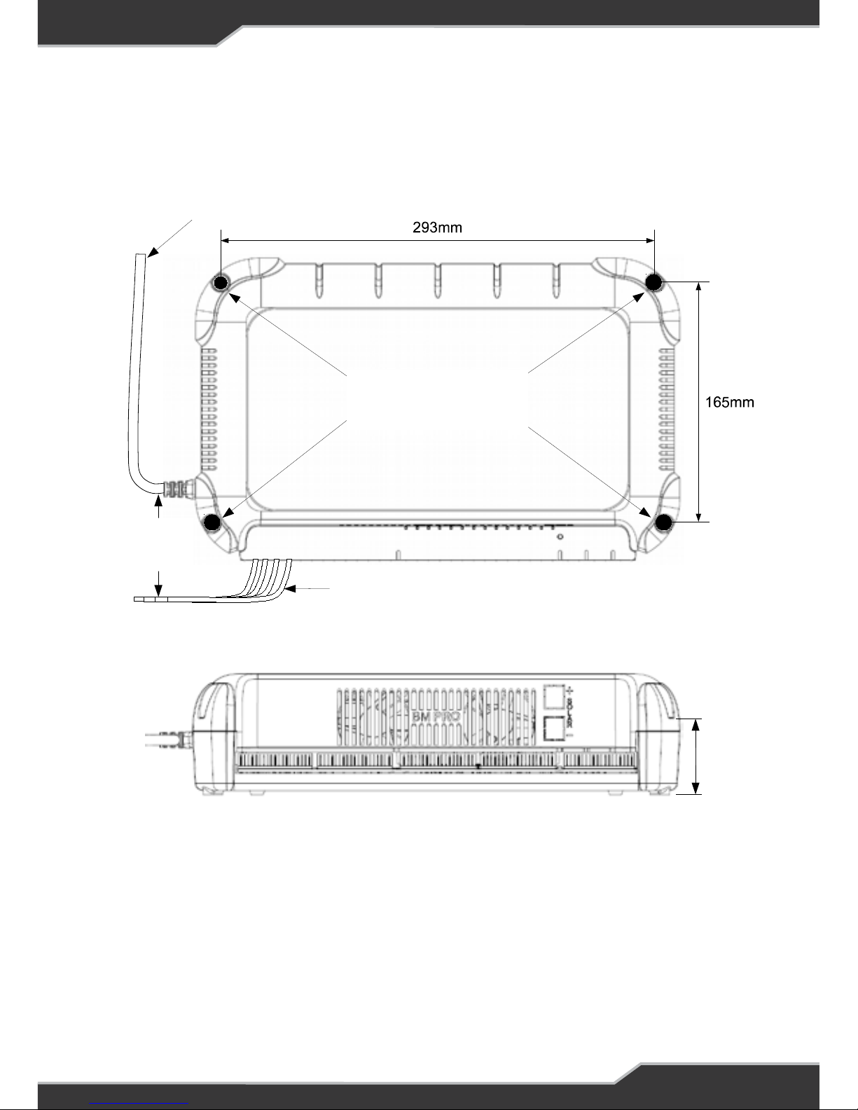
The preferred orientation is with the load connection at the bottom, as shown in
Figure 1: Recommended Mounting Holes, and located such that there is a minimum
of 80 mm free air space from all vented sides of BatteryPlus35. This allows for the
lowest operating temperature of the internal electronics and highest reliability of the
product.
The final enclosure must also provide adequate ventilation to the outside world (or
larger internal cavity) to prevent excessive heating of the air within the enclosure.
At normal room temperature (25°C), the unit is rated to provide full power in both
vertical and horizontal orientations. At elevated temperature up to 50°C, the output
current is de-rated to 32A.
The enclosure air temperature can easily exceed 50°C if
adequate ventilation is not provided.
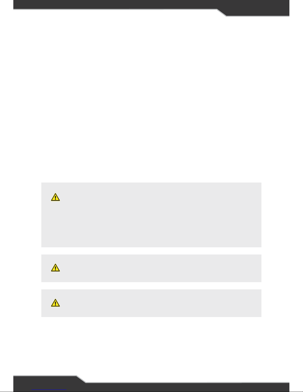
WARNING
The unit has over-temperature protection, meaning it will
shut down if its internal temperature rises above a safe
level. The unit will automatically restart once it has cooled
to an acceptable level.
WARNING
DO NOT install BatteryPlus35 in the same compartment
where flammable material such as petrol is stored.
WARNING
Ensure that the BatteryPlus35 is not exposed to any
liquids during installation or the installed environment.
Page 11
11
Figure 1: Recommended Mounting Holes
Mains Cable
Output Cables
Mounting Holes (x4)
Countersunk screw
Recommended
50mm
screw slot
MIN 10mm
Gap required
At all times
Figure 1: Recommended Mounting Holes
Mounting
BatteryPlus35 should be securely mounted to a suitably strong surface, using 4 pre-
drilled mounting holes. Dimensional details are provided in Figure 1 below.
Page 12

12
Mains Cable
This is pre-cabled and fitted with a mains plug. Ensure that the connection to the
mains supply is in accordance with the national wiring rules, and that the earth
connection is installed. The mains cable must be at least 10mm away from the
output cables. See Figure 1: Recommended Mounting Holes. All DC connections
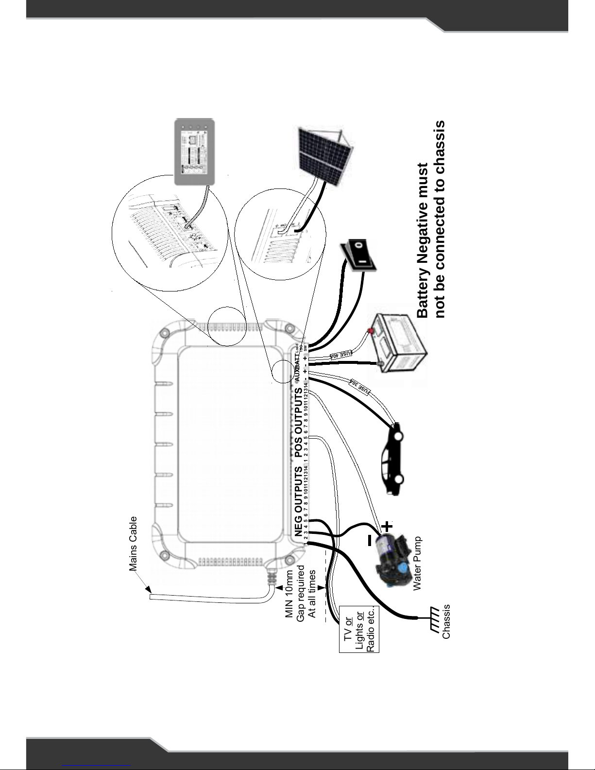
should be wired according to Figure 3: DC Wiring Diagram for BatteryPlus35SR and
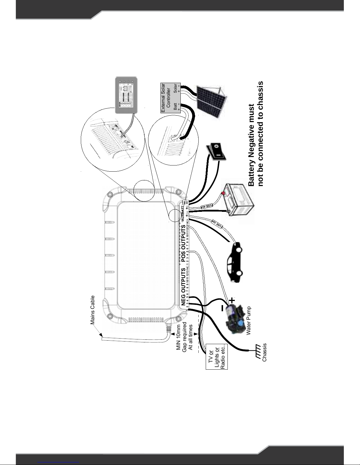
BatteryPlus35HA and Figure 4: DC wiring Diagram for BatteryPlus35PM.
The plug must be accessible during installation. If this is not possible, an accessible
mains disconnection switch must be incorporated in the mains wiring where the
plug is connected.
Wire Size
DC cables must be sized to carry the maximum full load current and to not exceed
the system volt drop requirements. The following cable sizes are recommended.
When running wires, if they pass through panels or wall, ensure the wires are
protected from damage by sharp edges. The use of cable glands is recommended.
WARNING
If the supply cord is damaged, it must not be replaced and
the appliance should be scrapped.
Table 1: Wire Size Recommendations
Current Minimum Wire Size
0 – 10A 1.0 mm² or 18 AWG
10 – 20A 3.0 mm² or 14 AWG
20 – 30A 5.5 mm² or 10 AWG
Load Connections
Up to 14 independently-fused loads, may be connected. Loads are attached using
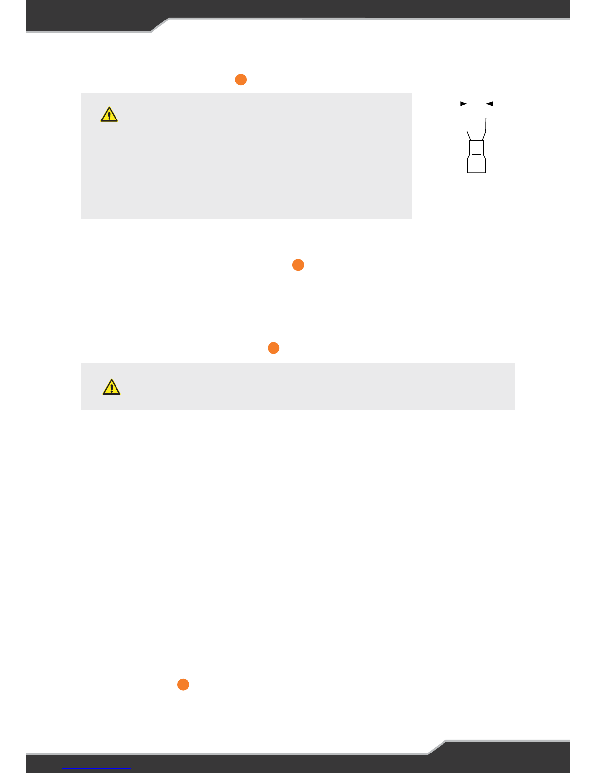
female spade Quick Connects (QC). See Figure 2: Quick Connect Dimensions.
Refer to Table 1: Wire Size Recommendations for wire size recommendations.
All load negative returns must be connected directly to the BatteryPlus35 negative
terminals only.
1
2
Page 13
13
WARNING
A fuse must be installed in the positive
connection of the battery. This fuse
MUST be as close as possible to the
battery. This fuse protects against
short circuits and reverse battery
conditions. A fuse rating no greater
than 40 Amps must be used.
Caravan Battery Connection
Connect the caravan battery to the terminals shown in Figure 3: DC Wiring Diagram
for BatteryPlus35SR and BatteryPlus35HA. The battery negative return must be
connected to the BatteryPlus35 “BATT-” only.
The battery negative must not be directly connected to the chassis.
In order to avoid incorrect current readings and battery capacity errors, DO NOT
make any connections directly to the battery.
6.8mm
Figure 2:
Quick Connect
Dimensions
The power supply terminal “AX” provides an alternative option for powering the loads
and charging of the batteries when mains voltages are not present. This input is to
be powered from a suitable +12 V system (e.g. a vehicle). The voltage of this external
DC power source should not exceed 14.8 V.
This input is isolated using an internal relay, so it is strictly an input; BatteryPlus35
will never supply current to anything connected to this terminal. The AX voltage must
be 0.5V greater than the battery voltage for charging to occur. If the current supplied
by the AX input is less than 2A then the charging will stop.
This is the only input for a car connection. Refer to AX Charging on page 26.
Note: BatteryPlus35 does not provide battery charge management when operating
in this configuration. In this configuration current and voltage control for the battery
must be provided from the external source.
Note: The BatteryPlus35 and loads can be powered directly from the Auxiliary input
and does not require a battery.
Solar Connection
This connection is for solar panel connection for the BatteryPlus35SRHA and for a
solar regulator/controller connection for the BatteryPlus35PM.
CAUTION
Suitable fuse protection MUST be provided for the “AX”
input. A fuse rating not exceeding 30 Amps must be used.
AX (Auxiliary) DC Input Connection
6
6
5
14
Page 14

14
BatteryPlus35PM solar input is to be connected with an external solar regulator with
solar panels. The external regulator or controller can be MPPT or PWM type.
The output of the solar regulator must not exceed 30A and should provide a suitable
charging profile for the batteries installed in the system.
Solar panel and external regulator selection must be suitable for optimum changing
current in order to prolong the life of the battery.
Consult the external solar regulator and battery specification details for more
information.
This Input will be left ON when AC mains or Aux is present.
BatteryPlus35SR and BatteryPlus35HA Versions
BatteryPlus35SR/HA have a solar input to which standard 12V solar panels are to be
connected to this input. This input is internally connected to a Maximum Power Point
Tracking (MPPT) charger which is able to charge a 12V battery system and provide
power to the loads. This MPPT charger is a smart, multi-stage, 450W regulator
which is capable of delivering up to 30A. The charging stages are described in Figure
8: Charging Algorithm.
The voltage generated by the solar panel must exceed 17.5V for two minutes in order
for the solar panels to start charging the batteries.
The AX and solar sources can be both enabled at the same time if available.
Solar Panels
Standard 12V solar panels are to be used. Solar panels may be paralleled and its
(Voc) open circuit voltage must not exceed 25V.
Installing the Solar Panel
1. Make sure there is no mains and no auxiliary input
2. Connect the battery to the battery terminals
3. Connect solar panels directly to the solar input ensuring correct polarity.
See Figure 3: DC Wiring Diagram for BatteryPlus35SR and BatteryPlus35HA
All connections must be sound and all QCs must be crimped well. Push each QC all
the way into the blade connector.
BatteryPlus35PM Versions
CAUTION
DO NOT connect solar panels directly to this input.
Page 15

15
Remote Load-Isolator Switch Connection
BatteryPlus35 allows for remote control of the load connections by two methods,
remote switch via the Trek display (optional accessory) and hardware remote switch
terminals. All loads can be turned off by operation of either switch. This feature can
be used to store the caravan when not used.
Both methods are described below. If both methods are installed, the dedicated
remote switch overrides the remote switch via Trek.
Remote Switch via Trek Display
The load outputs on BatteryPlus35 can be controlled via Trek (purchased
separately). Trek has a dedicated button to switch all loads off and on. When the
loads are OFF the unit enters into ECO mode.
Battery charging is not affected by this switch.
For detailed information and more, see page 31.
Note: This function is not available on the RVView.
Remote Switch via Hardware Remote Switch Terminal (RSW)
A pair of contacts, item in Name and Function of Parts, are provided for
connection to the external switch. When this switch is shorted, all loads are
disconnected from all power and the unit is put into storage mode.
Battery charging is not affected by this switch.
Any accessories connected to the communication bus are turned off.
Any convenient switch and wire size may be used.
Communication Bus Connection
The communication bus connection is used to connect the BatteryPlus35 and
external BMPRO accessories via a data cable.
Note: See the BMPRO by Setec website for cable accessories.
Installing Controllable Pumps
The BatteryPlus35 has a feature which enables two output channels to be remotely
controlled from the Trek unit. These outputs are used to control two pumps which
can only be switched ON and OFF, if installed. The pumps have to be connected to
outputs and . If only one pump is required to be controlled, connect it to output
Figure 3: DC Wiring Diagram for BatteryPlus35SR and BatteryPlus35HA and Figure
4: DC Wiring Diagram for BatteryPlus35PM shows a single pump connected.
7
7
9
1313 14
Page 16
16
16
Mains Cable
MIN 10mm
Gap required
At all times
NEG OUTPUTS POS OUTPUTS
AUX
- +
BAT T
- +
Load
ISO
SW
1 2 3 4
5
6
7
8 9 10 111213 14 1 2 3 4
5
6
7
8 9 10 11121314
F
U
SE
4
0
A
F
U
S
E
3
0
A
TV or
Lights or
Radio etc..
Water Pump
Battery Negative must
not be connected to chassis
Chassis
Figure 3: DC Wiring Diagram for BatteryPlus35SR and BatteryPlus35HA
Output 13 Pump 1
Output 14 Pump 2
Output 1 Persistent output, on even if battery button on Trek is pushed
BatteryPlus35SR / BatteryPlus35HA
Page 17
17
Output 13 Pump 1
Output 14 Pump 2
Output 1 Persistent output, on even if battery button on Trek is pushed
Figure 4: DC Wiring Diagram for
BatteryPlus35PM
17
Mains Cable
MIN 10mm
Gap required
At all times
NEG OUTPUTS POS OUTPUTS
AUX
- +
BATT
- +
Load
ISO
SW
1 2 3 4
5
6
7
8 9 1011 1213 14 1 2 3 4
5
6
7
8 9 1011 121314
F
U
S
E
3
0
A
TV or
Lights or
Radio etc..
Water Pump
Battery Negative must
not be connected to chassis
Chassis
Solar
+
-
Batt
+
-
External Solar
Controller
Figure 4: DC Wiring Diagram for BatteryPlus35PM
BatteryPlus35PM
Page 18

18
Battery Connection / Disconnection Procedure
WARNING
Sparks have the potential to cause an explosion should
combustible gases be present. The following procedures
are designed to minimise the risk of spark generation
while connecting or disconnecting the battery. The
positive terminal of the battery must not be connected to
the chassis of the vehicle.
Battery Disconnection Procedure
The caravan battery should be disconnected as per the following steps.
1. Remove mains power to the BatteryPlus35
2. Disconnect Solar and Aux inputs from the BatteryPlus35
3. Turn off all 12 V equipment connected to BatteryPlus35
4. Disconnect the negative battery terminal
5. Disconnect the positive battery terminal
Battery Connection Procedure
The caravan battery should be connected as per the following steps.
1. Confirm no mains power, auxiliary power, or solar power is connected to the
BatteryPlus35
2. Connect the positive battery terminal
3. Connect the negative battery terminal
4. If a Trek is installed, set the total battery capacity (refer page 31) to ensure
accurate forecasting
Page 19
19
BATTERIES
Note: This battery charger is rated to charge battery banks of up to 600 Ah capacity.
When using batteries with this product, always consult with the battery manufacturer
for a detailed description of the installation, use and maintenance of the battery.
The chemistry that the product can charge is detailed below:
BatteryPlus35
SR HA PM
Battery Chemistry
Lead-Acid Only
Lead-Acid
LiFePO4
Lead-Acid Only
Table 2: Product name and their corresponding chemistry
A BatteryPlus35HA can be used to charge a LiFePO4 battery but will need to be
set using a Trek before use. At default the BatteryPlus35HA is set to Lead-Acid
chemistry.
The battery will charge faster when all loads in the caravan are small.
Note: Lead-acid battery may be Gel, AGM, Sealed, Wet or Lead crystal. Consult the
battery manufacturer for profile and maximum voltage and set this using the Trek.
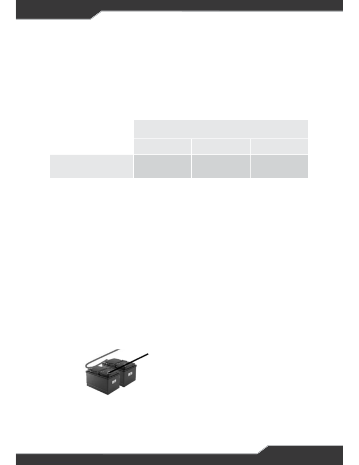
Paralleling Batteries
When paralleling batteries together, all batteries MUST be
• of the same type and chemistry, e.g. deep cycle battery
• of the same capacity, e.g. 100 Ah
• of the same manufacturer
• fully charged before connecting them together
Figure 5 is a recommendation, an auto-electrician may wire this based on system
requirements.
Figure 5: Recommended wiring for
connecting batteries in parallel.
Page 20

20
Storage
If the caravan is to be stored for a long period of time, first fully charge the battery
and ensure all loads are disconnected, see section Remote Load-Isolator Switch
Connection. It is recommended to recharge the battery at least once every month
or be maintained from the solar panel if installed. Regular recharging will prevent
the battery from becoming deeply discharged—a condition which can significantly
shorten battery life.
Deeply Discharged Batteries
Lead-Acid Batteries
This battery charger is not designed to charge deeply discharged batteries. Its
effectiveness in charging such a battery is a function of the depth of discharge and
the battery size. Bigger (higher capacity) batteries will be more troublesome in this
respect.
If a battery has become deeply discharged and BatteryPlus35 will not charge it,
remove the battery (see Battery Connection/Disconnection Procedure on page 18)
and charge it with a stand-alone charger. Once the battery voltage has recovered to
normal levels it may be reinstalled.
LiFePO4 Batteries
If a LiFePO4 gets deeply discharged and its internal Battery Management System
(BMS) turns off the battery voltage. The BatteryPlus35 will provide a 14.6V on its
output to restart the battery BMS and charge the battery.
SERVICING
This product contains hazardous voltages and energy hazards, which can result in
death or injury.
Only properly qualified service personnel may service it.
There are no internal user serviceable parts.
WARNING
Select the appropriate chemistry profile using the Trek,
Lead acid or LiFePO4. If unsure consult with battery
manufacturer or dealer.
WARNING
DO NOT install battery in the same compartment where
flammable material such as petrol is stored.
Page 21
21
FUNCTIONAL DESCRIPTION
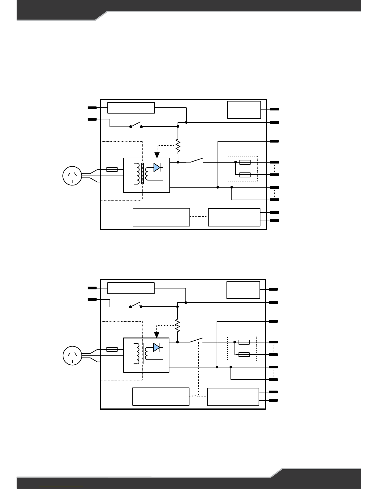
Functional Diagram
Figure 6: Functional Schematic BatteryPlus35SR/HA
FUNCTIONAL DESCRIPTION
FUNCTIONAL DIAGRAM
Figure 6: Functional Schematic BatteryPlus35SR/HA
AC Input
Isense
14 x Load
Outputs
Caravan Battery
AC / DC
Vad j
Battery Low-voltage
Disconnect Circuit
Load Remote-
disconnect Circuit
Remote Load
on/off Input
Battery –Ve
1mΩ
14 x Load
Returns
Car Battery
BAT –VE
BAT +VE
AUX +
–VE
L1 – L14
LOAD SWITCH
ELECTRONIC
LOAD FUSES
Solar Input MPPT Tracker
COMMS
COMMS BUS
Figure 7: Functional Schematic BatteryPlus35PM
AC Input
Isense
14 x Load
Outputs
Caravan Battery
AC / DC
Vadj
Battery Low-voltage
Disconnect Circuit
Load Remote-
disconnect Circuit
Remote Load
on/off Input
Battery –Ve
1mΩ
14 x Load
Returns
Car Battery
BAT –VE
BAT +VE
AUX +
–VE
L1 – L14
LOAD SWITCH
ELECTRONIC
LOAD FUSES
External
Solar Input
Solar Input
COMMS
COMMS BUS
Figure 7: Functional Schematic BatteryPlus35PM
Page 22

22
AC/DC Power Supply
BatteryPlus35 provides an isolated output for powering of the loads and charging of
the battery. It enters into power supply mode if it is set to charge a lead-acid battery
and is powered by AC mains without the battery, providing an output voltage of 12.8V.
When a battery is detected, Battery current is sensed and monitored by the power
supply to limit the charging current. Refer to Charging Profile on page 26 for more
details.
Multiple Inputs and Blending
BatteryPlus35 may have many active sources at one time. These sources include
the battery, AC mains, solar input and auxiliary (AX) input. Multiple sources will be
turned On to deliver power to the system. Their priorities are outlined below:
BatteryPlus35HA and BatteryPlus35SR
Scenario 1: If AC Mains and solar sources are available, then AC Mains is the
dominant source.
Scenario 2: If AC Mains and Auxiliary sources are available, then AC Mains is the
dominant source.
Scenario 3: If Solar and Auxiliary sources are available, then Solar and Auxiliary
inputs are both be turned ON.
Scenario 4: If AC Mains, Solar and Auxiliary sources are available, then AC Mains is
the dominant source.
BatteryPlus35PM
Scenario 1: If AC Mains and external solar sources are available, then AC Mains and
solar inputs are both turned ON.
Scenario 2: If AC Mains and Auxiliary sources are available, then AC Mains is the
dominant source.
Scenario 3: If External Solar and Auxiliary sources are available, then Solar and
Auxiliary inputs are both turned ON.
Scenario 4: If AC Mains, Solar and Auxiliary sources are available, then AC Mains
and solar input are both turned ON.
Note: If no battery is attached to the BatteryPlus35 and is set as a lead acid charger,
the nominal voltage is 12.80V when operating on Mains.
Page 23

23
Fault Protection
The power supply provides automatic protection for short-circuit overload, overvoltage, and over-temperature situations.
In overload, over-temperature and short-circuit condition the power supply will shut
down. It will then automatically attempt to restart every 30 seconds until the fault is
removed.
For Reverse Battery protection an external battery fuse must be installed, refer to
Battery Fusing.
Fusing
Electronic Load Fuses
Each load output is protected by internal electronic fuse. Electronic fuses are low
maintenance and do not require replacement if a short circuit or over current
condition occurs. L3 to L14 are 10A, and L1 and L2 are 15A outputs. Their locations
are shown in Name and Function of Parts.
L1 is also set as a persistent load, allowing for this output to stay on if the battery
voltage falls below low voltage threshold 1 or if the Remote switch button via the
Trek is pushed. This output will turn off if the battery discharges down to low voltage
threshold 2. Only light or temporary load MUST be added to L1, such as an electric
step.
Electronic fuses eliminate the requirement for the user changing fuses, when a
short occurs. The status of the output can be checked by LED indicators shown in
Name and Function of Parts. The output will return once the fault is removed.
Note: The LED indicators have a narrow viewing window. One has to be directly above
them in order to view them.
Battery Fusing
Battery fusing with maximum rating of 40A must be added to the positive line of the
battery terminal and be installed as close as possible to the battery. See location
shown in Figure 3: DC Wiring Diagram for BatteryPlus35SR and BatteryPlus35HA
Auxiliary (AX) Fusing
AX fusing must be added to the positive line of the AUX+ terminal. A fuse rating
not exceeding 30 Amps must be used. See location shown in Figure 3: DC Wiring
Diagram for BatteryPlus35SR and BatteryPlus35HA
Page 24

24
Mains Fusing
The AC mains input is protected by an internal fuse of quick acting, high breaking
capacity type and rated at 250V 10A.
Low Voltage Disconnect Modes
Low Voltage Disconnect (LVD) is a feature of BatteryPlus35 that protects the battery
from deep discharge preventing battery health deterioration. The are two LVD modes
of protection for the battery, Eco mode and Storage mode.
ECO Mode
If the battery voltage drops below the ECO mode threshold, then the load outputs L2
to L14 are turned off, while L1 is left on. The communication bus and the accessories
connected to this bus are left on.
If no sources are available, a temporary recovery can be done by cycling the remote
Isolation switch on the BatteryPlus35 or pressing the battery button on the Trek, this
will turn on all the loads for short time.
In this mode, a full recovery can only be done if the Battery voltage rises above the
recovery threshold or if any power source is available, all outputs will be turned back
on.
Storage Mode
If the battery discharges further and its voltage drops below the storage mode
threshold, output L1 to L14 are all turned off. In this state any accessory connected
to the communication bus is also turned off.
In storage mode the battery current drain is less than 15mA.
If no sources are available, a temporary recovery can be done by cycling the remote
Isolation switch on the BatteryPlus35. All loads will be turned on for short time.
In this mode, a full recovery can only be done if a power source is available and the
battery voltage rises above the recovery threshold.
Table 3: ECO and storage mode thresholds
Lead Acid LiFePO4
ECO mode threshold
10.5V 12.0V
Storage mode threshold
9.8V 11.5V
Recovery threshold
12.8V 13.8V
ECO And Storage Mode Thresholds
Page 25

25
Battery Charging Management
To maintain the battery in a good state of health, an intelligently controlled charging
algorithm is used. The purpose is to ensure that the correct voltages are applied
to the battery terminals at the appropriate times throughout its usage cycle. For
blending with multiple sources refer to Multiple Inputs and blending on page 22.
AC Mains Charging
The BatteryPlus35 is a full battery management system with a multi-stage battery
charger including soft- start, bulk-absorption and float charging modes to ensure
long battery life. BatteryPlus35SR and BatteryPlus35PM can only charge a Lead-
Acid battery, while the BatteryPlus35HA can charge Lead-Acid and LiFePO4 battery
types.
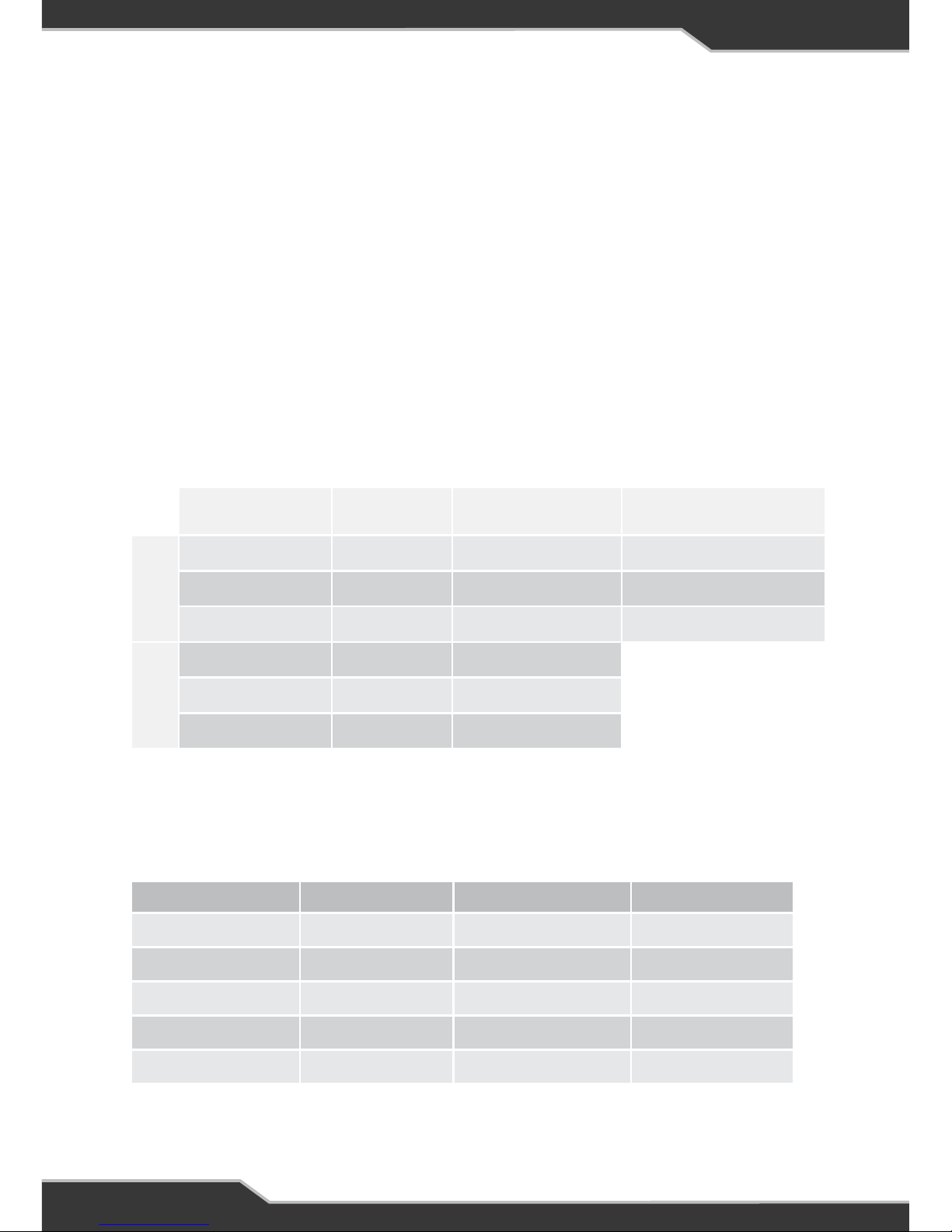
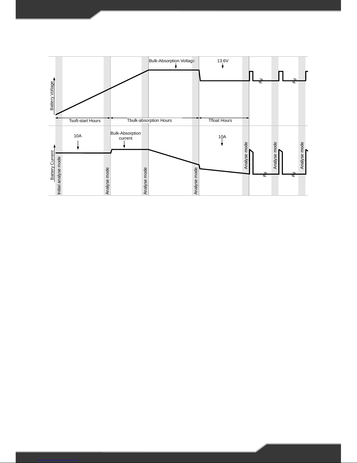
Details of the charging profile and settings can be found in Figure 8: Charging
Algorithm and Table 4: Charging voltage and current settings. The maximum time in
each mode is outlined in Table 5: Charging mode time maximum limit.
The power supply is able to deliver 35A maximum to the battery and loads. If
significant load current is present, the maximum battery charging current will be
reduced accordingly.
Note: that for BatteryPlus35 to operate in the manner described above, all loads
must be connected to load terminals, not directly to the caravan battery.
Solar Charging
Solar Charging with BatteryPlus35SR and BatteryPlus35HA
The BatteryPlus35SR/HA has an in built MPPT solar regulator. This solar regulator
follows the same changing settings as described in Figure 8: Charging Algorithm
and Table 4: Charging voltage and current settings. The current that can be delivered
to the system for solar relies on the limitations of the panels available and various
condition at the time.
The voltage generated by the solar panel must exceed 17.5V for two minutes in order
for the solar panels to start charging the batteries.
Solar Charging with BatteryPlus35PM
The BatteryPlus35PM charging currents relies on the external charger that has
been connected. The power of the external solar source needs to sized according to
the battery size, consult external solar controller manufacturer for correct number
of panels, charge profile and installation.
Page 26
26
AX Charging
There is no current or voltage control for charging the battery from the auxiliary
source. This is a simple on-off input. The charging current and voltage relies on the
external source.
The AX input voltage must be greater than the battery voltage for the internal relay
to turn on. Once turned on the AX input will continue to provide power until this input
current drops below 2A or is greater then 27A.
When this input is connected to a car to provide the power to the system, It is
recommended to disconnect the car output from the AX, if the alternator is not
running as this may discharge the car battery.
Battery Capacity Soft-start Bulk-Absorption Float
≤ 100AH 6 Hours 5 Hours 6 Hours
150AH 6 Hours 7.5 Hours 6 Hours
200AH 6 Hours 10 Hours 6 Hours
250AH 6 Hours 12.5 Hours 6 Hours
≥ 300AH 6 Hours 15 Hours 6 Hours
Charging Time
The maximum time that the BatteryPlus35 will stay in each mode is as follows:
Table 5: Charging mode time maximum limit
Table 4: Charging voltage and current settings
Charge Mode Voltage Set BatteryPlus35HA BatteryPlus35SR/PM
LEAD ACID
Soft-start 14.4V 10A 10A
Bulk-Absorption 14.4V 30A 20A
Float 13.6V 10A 10A
LiFePO4
Soft-start 14.6V 10A
Bulk-Absorption 14.6V 30A
Float 13.6V 10A
Charging Profile
The charging current and voltage settings are as follows:
Page 27
27
Charging Algorithm
Tfloat Hours
Bulk-Absorption Voltage
Battery Voltage
Bulk-Absorption
current
10A
Battery Current
Tsoft-start Hours
Analyse mode
Initial analyse mode
Analyse mode
Analyse mode
Analyse mode
Analyse mode
Analyse mode
10A
13.6V
Tbulk-absorption Hours
Note: Bulk and Float Charging times can be changed by changing the battery capacity using the Trek.
Analyse Mode: BatteryPlus35 assesses the battery, sources and time continuously at all times. In
analyse mode the charger uses all information to decide what needs to be done next.
Bulk Absorption Mode
During this mode the battery is
charged with a limit of
bulk-
absorption current limit
until
the battery voltage reaches
bulk-absorption voltage limit
and
charge current of less than 2A.
Then it changes to Float Mode.
This mode has a time limit of 5hrs
for a 100Ah battery. If the battery
is not charged within this time, the
charger will automatically enter
Float Mode and will repeat itself in
6hrs time.
If charging from solar, the same
charging profile is followed –
within the limitations of the power
available from the panels at that
time.
Soft Start Mode
AC Mains Charging
When the battery is
less than 9.5V, all
loads are disabled and
the charging current
is limited to 10A. The
charger charges at this
rate until the battery
voltage is 10.5V.
Solar Charging
When the battery is
less than 10.5V, all
loads are disabled and
the charging current
is limited to 10A. The
charger charges at this
rate until the battery
voltage is 12.3V.
Float Mode
Once in Float Mode, the charge current is
limited to 10A and keeps the battery topped
up.
This mode has a time limit of 6hrs for a
100Ah battery. When this time is reached
the charger will go back to Bulk Absorption
Mode.
Charging Steps Repeated
Charging Algorithm
Page 28
28
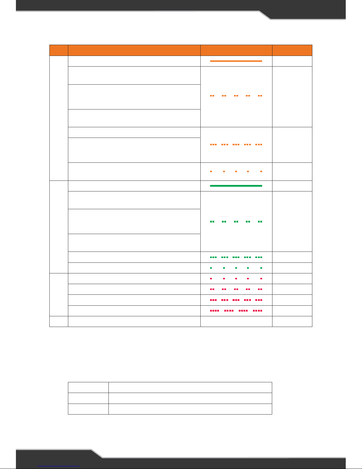
Load Output Status Indicators
A LED for each load output indicates the status of output. There are 14 LEDs for 14
outputs.
Colour Code Flash Status
Orange: Charging
AC mains is the source and is in bulk mode Solid
BatteryPlus35SR/HA
Solar is the source and is in bulk mode
2 flashes
BatteryPlus35SR/HA
Solar and Auxiliary available at the same time and
Solar is in bulk mode
BatteryPlus35PM
Solar is the only source and Solar current >1A
Auxiliary is the only source and Aux current is >2A
3 flashes
BatteryPlus35PM
Auxiliary and Solar available at the same time and
Aux current is >2A and Solar is >1A
Battery Voltage <12V and >7V and AC mains or
solar input is available
1 flash
Green: OK
AC mains is the source and is in float mode Solid
BatteryPlus35SR/HA
Solar is the source and is in float mode
2 flashes
BatteryPlus35SR/HA
Solar and Auxiliary available at the same time and
Solar is in float mode
BatteryPlus35PM
Solar is the only source and Solar current <1A
Auxiliary is the only source and Aux current is <2A 3 flashes
No sources available and house battery is OK 1 flash
Red: Error
Fault: Over-temperature 1 flash
Fault: Battery Fault 2 flashes
Fault: Solar Fault 3 flashes
Fault: Other Fault 4 flashes
Battery low voltage and no sources available All off All off
Green Output OK
Red Fault on the Output
OFF Low battery voltage or remote load isolating switch
Page 29
29
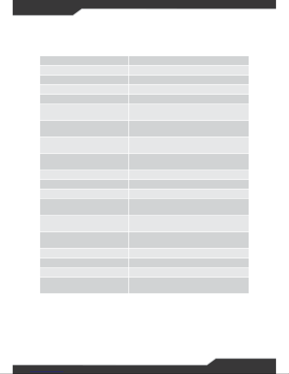
Input Voltage Range: 100VAC to 240 VAC nominal, ±10%, 50-60 Hz
Input Surge: < 40 A (cold start)
Output Current: 35A Continuous (load + battery current)
Factory Set Voltage: 13.65 V (float voltage)
Output Ripple Voltage: <150 mV
BatteryPlus35SR/PM
Battery Current Limit:
20 A max
BatteryPlus35HA
Battery Current Limit:
30 A max
Battery Connect:
12.8 ± 0.2 V (after LVD event) Lead-Acid
13.8 ± 0.2 V (after LVD event) LiFePO4
Low Voltage Disconnect:
10.5 ± 0.2 V Lead-Acid
12.0 ± 0.2 V LiFePO4
Battery Drain after LVD: < 15 mA
AC/DC Efficiency: > 83 %
Cooling Fan: Thermally controlled
BatteryPlus35SR/HA
Solar Output Current:
30A (nominal)
BatteryPlus35SR/HA
Solar Start Voltage
17.5V
BatteryPlus35SR/HA
Solar Input Voltage
15V to 25V (after start-up)
Ambient: 0°C – 50°C
Communication: Communication bus available
Weight: 2 kg
Standards:
Safety: IEC60335-2-29, IEC62109-1,
EMC: CISPR 14, Approvals: RCM,
SPECIFICATIONS
Page 30
www.teambmpro.com
SYSTEM MANUAL
Trek
Page 31
31
INTRODUCTION
Safety Precautions
Please read the Safety Precautions carefully before installing the unit.
Failure to observe these instructions properly may result in
property damage or personal injury, which may be serious
depending on the circumstances.
Refer to the installation section before operating. Correct installation is the most
critical factor in ensuring the safe use of the power supply. If every consideration
of these instructions has been satisfied the power supply will be safe to operate.
As this unit is powered by a communication cable it is critical that all connections
and cables are in a good and working order and properly connected.
Do not allow water or other liquids to enter the installation area.
CAUTION
Accessories
The following accessories are provided with Trek.
• A Trek Unit
• Front Fascia Cover
• Data Cable 10m
• Tank Loom
• Trek Manual
Other Required Items
• 4 counter sunk screws for mounting, refer to Installing Trek for more details.
Page 32

32
About Trek
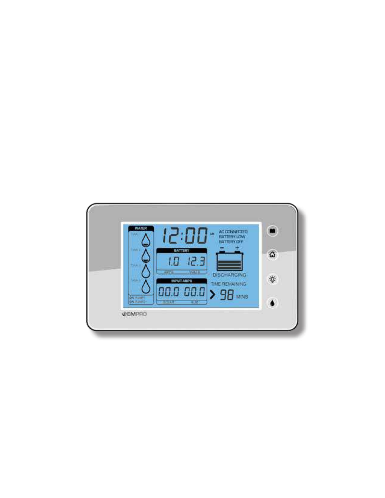
The Trek is a display and control unit that connects to BatteryPlus35 and displays
a range of battery and water tank information. Its backlit LCD displays information
including:
• Battery voltage
• Battery charging and discharging currents
• Auxiliary and solar charging currents
• Battery charge status
• Time remaining to discharge
• Level indication of up to 4 water tanks
• Time am/pm
• Water pump status
• Battery on/off status
Features also include:
• Back light which can be set as a night light
• Button to control 2 water pumps through BatteryPlus35
• Button to disconnect the battery from the loads
Glossary
Loads
Consists of any appliance connected to the output terminal of the BatteryPlus35
including lights, TV, radio, etc.
Sources
Consists of any device that can supply power to BatteryPlus35 and its loads, such as
solar input, battery input, aux input and AC input.
BatteryPlus35 / BP35
Integrated battery charger and power supply that converts 240VAC, Solar or Auxiliary
DC power to 12V DC which powers loads or charges a battery and works with the
Trek.
Page 33
33
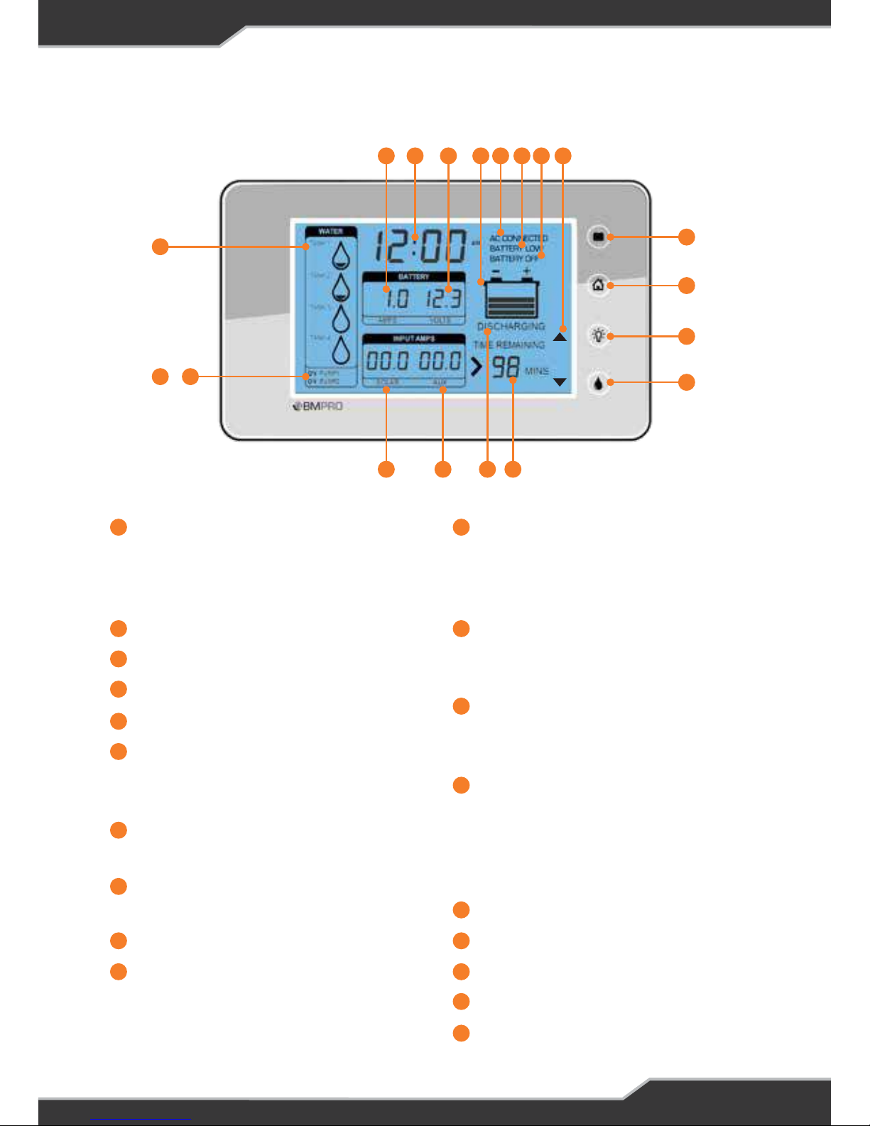
Name and Function of Parts
Tank 1 / Tank 2 / Tank 3 / Tank4
Water tank level indicators. These
can also be turned into waste water
tanks.
Pump 1 Status Indicator
Pump 2 Status Indicator
Solar Current
Aux Current
Battery Charge State
This shows if the battery is charging
or discharging
Time Remaining
Time until battery flat
Water Pump Button
Enables/disables the water pump
Backlight Button
Home Button
Home button is used for setup
functions
Battery Isolate Button
When paired with a BatteryPlus35,
this switch will isolate the battery
from the loads
Setup Mode Indicators
These indicators only appear when
in setup mode
Battery Off
Appears when the Battery is
isolated
Battery Low
Appears only when Battery voltage
is less than the low voltage warning
threshold. This is set in the Battery
alarm menu
AC Connected
Charge Bar Graph
Battery Voltage
Clock
Battery Current
1 11
2 12
3
4
13
5
6
14
7
16
15
8
17
9
18
10
19
1
4
19 18517 16615 14713 12
8
9
10
11
2 3
+
Page 34
34
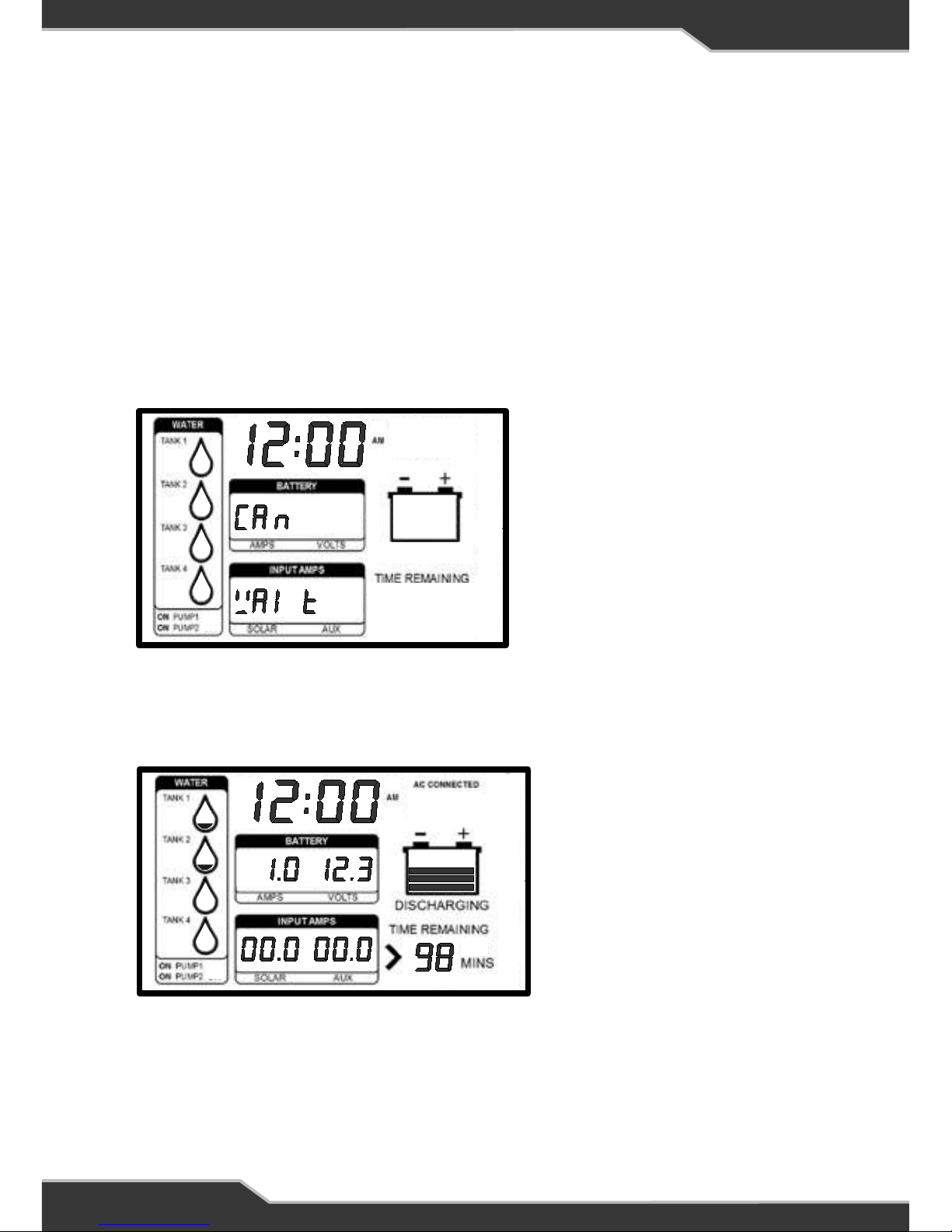
Figure 2: Trek display when first powered up
OPERATION
In normal power-on mode the unit displays the Home screen.
Trek is designed to interface with BatteryPlus35. The functionality described below
assumes Trek has been correctly connected to BatteryPlus35.
The Trek will turn off if battery voltage is too low.
On Power Up
On Power up Trek will display “CAN WAIT” until communication between Trek and
BatteryPlus35 is established.
When communication between Trek and BatteryPlus35 is established, Trek will
display information similar to the Figure 3.
Figure 3: Trek displaying information after initial power on, typical home screen.
If Trek cannot establish this communication within 30 seconds, then “CAN Err
To” will be displayed. If this occurs then there is a fault in the system. Check all
connections.
Clock
Battery Current
18
19
Clock
Battery Current
18
19
Figure 2: Trek display when first
powered up
Page 35

35
Description of Display Elements
Tank 1 / Tank 2 / Tank 3 / Tank 4
Trek can support up to 4 tank sensors and can be set-up as fresh water and/or
waste water tanks. By default, only Tank 1 and Tank 2 are enabled as fresh water
tanks. These indicate the approximate water level in each of the tanks.
The display differences between each of the configurable states are as follows:
• Enabled as a fresh-water tank: the bottom level-segment flashes when the tank
is empty.
• Enabled as a waste-water tank: all segments flash when the tank is full.
• Disabled: no level segments are displayed.
Pump Status Indicator
These indicators show if the pumps installed are enabled or disabled. This is
controlled by the pump button .
Solar Current
This is the current that is drawn from solar input of the BatteryPlus35. If solar is
present but not used, the Trek will display “00.0”, while if there is no solar source
available then “--.-” is displayed.
Aux Current
This is the current that is drawn from the auxiliary(AX) input of the BatteryPlus35. If
aux source is present but not used, the Trek will display “00.0”, while if there is no
aux source available then “--.-” is displayed.
Battery Charge State
A bar graph showing the state of charge of the battery. “CHARGING” or
“DISCHARGING” is displayed under this bar graph
Time Remaining
Indicates the estimated time remaining for the battery to be discharged to empty,
assuming it continues to discharge at the current rate.
Time less than 180 minutes will be displayed in minutes, while if its greater then it
will be displayed in hours and If the remaining time is greater than 199 hours, the
display shows “>199 HRS”.
1
4
8
5
7
2 3
+
6 16
+
Page 36

36
Setup Mode Indicators
These indicators only appears when Trek is in setup mode. The icons indicate the
functions of the buttons adjacent to it. The icons include edit, back, & symbols.
Battery Off
This indicator is displayed when loads are disconnected from all sources including
the battery. This is controlled by the battery isolate button and in conditions
where the battery is too low to be used. All other segments will also be turned off to
reduce current draw from the battery.
Battery Low
This indicator is displayed when the battery voltage is at or below the low voltage
warning threshold. For lead-acid battery the default is 11V and for LiFePO4 it is
12.3V. It is recommended to charge the battery if this annunciator is seen.
This is user configurable, refer to the Setup Mode section.
AC connected
This indicator appears only when BatteryPlus35 is connected to AC mains.
Volts
Displays the battery voltage.
The displayed value will flash if communication with an installed the BC300
(External Shunt) is lost. Refer to Appendix 1 to disable flashing.
Amps
Shows the charging or discharging current of the battery.
The displayed value will flash if communication with an installed the BC300
(External Shunt) is lost. Refer to Appendix 1 to disable flashing.
Clock
Displays a 12 or 24 hour clock. This is user configurable. Refer to the Setup Mode
section.
12
13
11
14
15
17
19
18
Page 37

37
Description of Buttons
Water Pump Button
This button controls power to the water pump outputs on BatteryPlus35.
When BatteryPlus35 and Trek are first powered, the outputs assigned for the pumps
are ON and Trek display “ON PUMP1” and “ON PUMP2”
Pump 1 To switch pump 1 On/Off press the water pump button once
Pump 2 To switch pump 2 On/Off press and hold pump button until the
desired change is seen.
In setup mode the water pump button turns into the “ button”.
Backlight Button
Backlight button is primarily used to enable the backlight.
In setup mode the backlight button is the “ button”
Backlight Functionality
Turn on backlight temporarily: Press any button to turn ON the backlight
temporarily and will automatically turn off after 30 seconds.
Turn on nightlight: Press and hold the backlight button until the backlight blinks
(approximately three seconds). The backlight will turn ON for 10 hours.
Turn off nightlight: Press and hold the backlight button until the backlight is OFF
Home Button
Pressing and holding the Home button for approximately 3 second puts Trek into the
setup mode.
In setup mode the home button is the “back button”.
Battery Button
The battery button is used to disconnect the battery, AC mains, auxiliary and solar
sources from the loads. Pushing the battery button will toggle the loads ON and OFF.
When Trek is first turned on the battery will power the loads and “BATTERY OFF”
is NOT displayed. When the battery button is pressed, the loads are disconnected
from the battery and “BATTERY OFF” will appear and all other segments will also be
turned off to reduce current draw from the battery.
In setup mode the battery button is the “EDIT button”.
8
8
9
10
11
13
8
2 3
Page 38
38
SETUP MODE
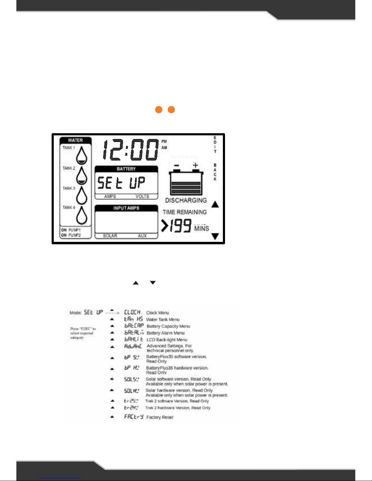
Enabling Setup Mode
1. Ensure the display is in normal mode (not in any setting mode).
2. Press and hold the HOME button for at least 5 seconds.
3. “SETUP” will be displayed in + location
4. Now you are in setup mode
Figure 4: Setup Mode
17 19
Figure 4: Set-up Mode
Setup Menu
When in setup mode, the or button can be used to scroll through the setup
menu. The list of options in the setup menu is as follows:
17 19
Page 39
39
If the Trek discovers any other accessory that is compatible, it will display the ID of
that device and its hardware and software version.
To exit menu, press and release the “Back” button a few times until the home screen
is seen.
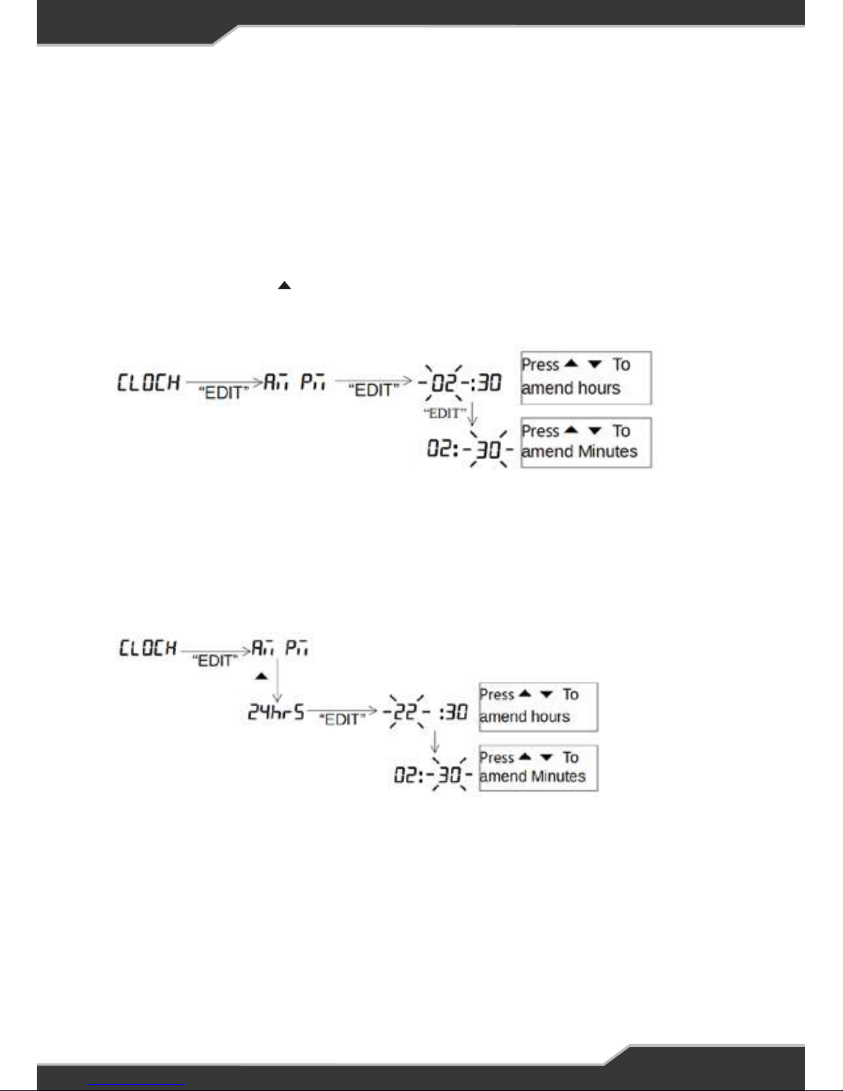
Clock Menu
Press and hold the HOME button until you see Setup
Press and release the button a few times until you see CLOCK
Setup 12hr Clock
AM and PM annunciators will automatically change as the time changes from
11 to 12.
To exit menu, press and release the “Back” button a few times until the home screen
is seen.
Setup 24hr Clock
To exit menu, press and release the “Back” button a few times until the home screen
is seen.
Page 40

40
Water Tank Menu
Water Tank Enable
This shows how to enable or disable the water tanks.
After enabling the required tank, allow for 15 seconds for the tank levels to update.
Press and hold the HOME button until you see Setup
Press and release the button a few times until you see tanks
To exit menu, press and release the “Back” button a few times until the home screen
is seen.
Water Tank Type (Fresh/ Waste)
This shows how to change the water tank from a fresh water to waste water tank.
To exit menu, press and release the “Back” button a few times until the home screen
is seen.
Page 41
41
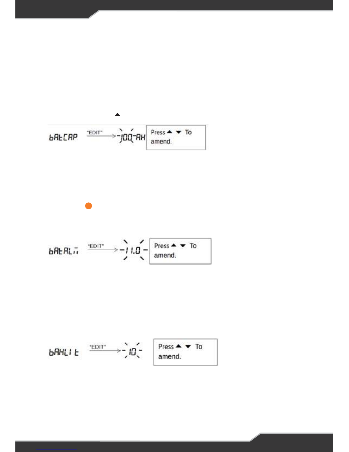
Battery Capacity Menu
When a new battery is fitted, set this to the nominal battery capacity (as marked on
the battery); doing this will assist the software in determining the actual capacity.
This shows how to change the battery capacity in AH. The battery capacity can be
incremented or decremented.
Press and hold the HOME button until you see Setup
Press and release the button a few times until you see BATCAP
To exit menu, press and release the “Back” button a few times until the home screen
is seen.
Battery Alarm Menu
This shows how to change the battery alarm. This parameter indicates when the
Battery Low annunciator starts to blink.
The alarm threshold can be incremented or decremented in steps of 0.5V. The alarm
threshold can be adjusted from 10.0V to 14.0V.
To exit menu, press and release the “Back” button a few times until the home screen
is seen.
LCD Backlight Menu
This shows how to change the LCD backlight brightness. The backlight brightness
can be incremented or decremented in steps of 10%. The brightness can be adjusted
from 0% to 100%.
To exit menu, press and release the “Back” button a few times until the home screen
is seen.
14
Page 42
42
WARNING: All saved
settings will be erased.
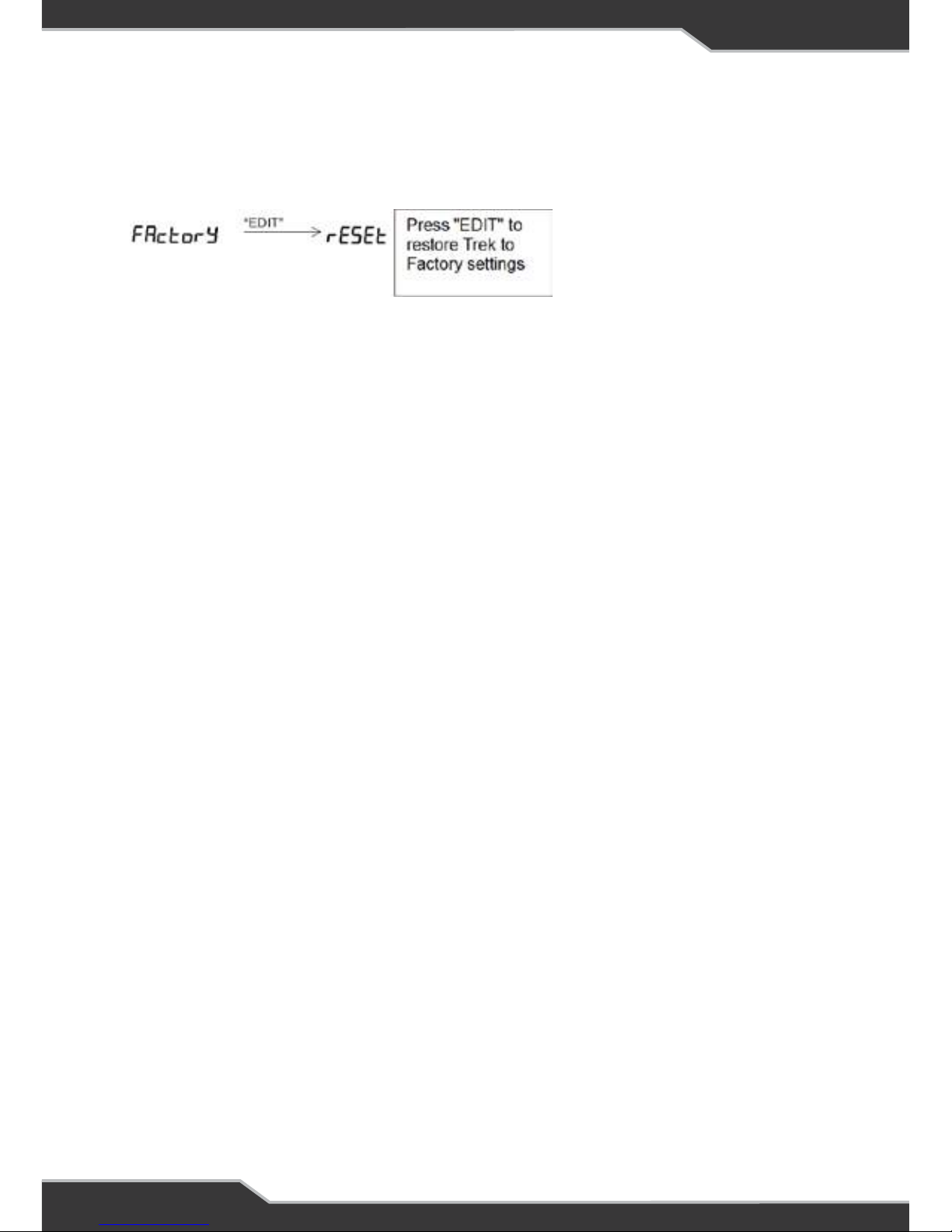
Factory Reset Menu
This shows how to restore Trek back to factory settings.
WARNING: All saved settings will be erased.
To exit menu, press and release the “Back” button a few times until the home screen
is seen.
NEW BATTERY INSTALLATION
Trek is a smart battery monitor that is able to learn the actual battery capacity and
thus provide more accurate “Time Remaining” feedback to the user.
When an existing battery is replaced by a new one or if it is a new installation, check
the capacity of the new battery and verify this in Battery Capacity Menu on page 16.
Change this as required.
Fitting a new battery and doing nothing else will result in the “Time Remaining”
display initially being inaccurate. It is recommended to charge the battery until Trek
shows the charging current is less than 2A. Disconnect mains, solar and auxiliary
before installing a new battery.
See BatteryPlus35 installation instructions for more information on the installation
of new battery.
CONNECTORS
At the rear of Trek are two connectors.
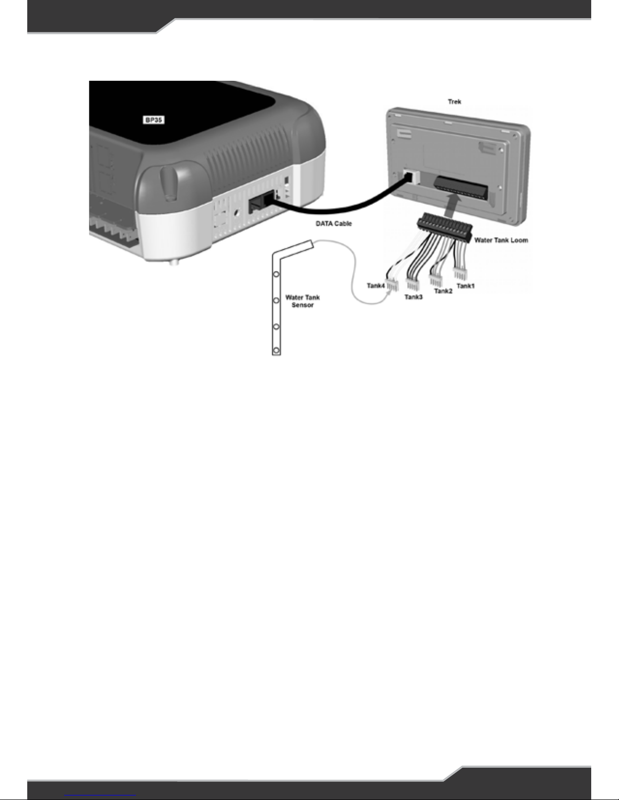
1. The communication bus connector which is a data cable that connects
BatteryPlus35 to Trek.
2. The Tanks Sensor connector with a detachable loom. This loom can be connected
to 4 digital tank sensors.
Page 43

43
INSTALLING TREK
Personnel
Installation is to be carried out only by suitably qualified personnel.
Installation Environment
Trek should be installed indoors where it will not be subject to water or other liquid
spills or splashes.
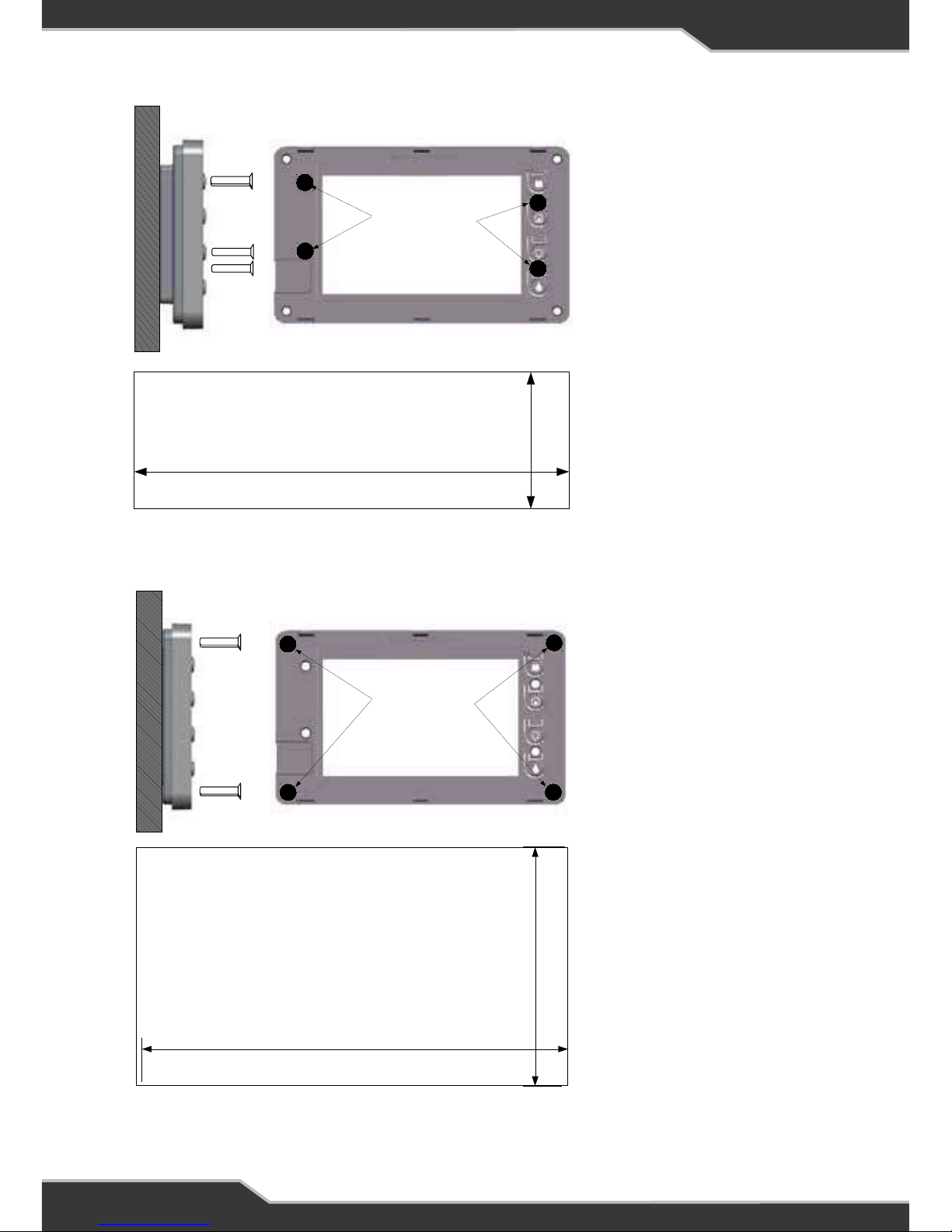
Mounting
Trek is designed to be mounted to the wall directly with counter sunk screws. It
can be mounted in two methods depending on the look and application required.
The mounting methods and required mounting holes are specified below. Cut-out
dimensions for each method are shown. These cut-outs are to be used to cut the
hole in the wall before fixing the unit.
After fixing Trek to the wall, remove the clear protective plastic from the front of the
display, then clip on the provided front fascia cover to Trek. Finally remove the clear
protective plastic from the front fascia.
Page 44
44
Figure 6: Mounting Method 2 (RECESS) Details
Mounting Holes
Countersunk screws
Recommended
Screw requirement for mounting method 2:
Screw type: Counter sunk
Diameter: 3.5mm max
Length: 20mm min
Mounting Holes
Countersunk screws
Recommended
74mm
134mm
Suggested cut out
size for Recessed mount
Screw Requirements
Mounting Method 2
Screw type: Counter sunk
Diameter: 3.5mm Max
Length: 20mm Min
Mounting Holes
Countersunk screws
Recommended
Mounting Holes
Countersunk screws
Recommended
33mm
105mm
Suggested cut out
size for Flush mount
Figure 5: Mounting Method 1 Details
Screw Requirements
Mounting Method 1
Screw type: Counter sunk
Diameter: 4.0mm Max
Length: 25mm Min
Page 45
45
Water Tank Level Wiring
Digital Sensor
1. Empty the water from the tank(s)
2. Choose a suitable side of the tank where the level-sensing can be located.
3. Drill the required hole in the tank
4. Install the tank sensor to the tank
5. Connect sensor connector to the water tank loom
6. Fill the tank(s) and check for water leaks around the bungs. Reseal as necessary.
7. Test operation of water level sensors, water pump switch, and Battery on/off switch.
Figure 7: Trek to BatteryPlus35 Wiring
Page 46
46
SPECIFICATIONS
Input Voltage: 8 — 15 Vdc
Battery Drain: < 21 mA (backlight off)
Low Voltage Disconnect:
10.5 ± 0.2 V Lead-Acid
12.0 ± 0.2 V LiFePO4
Ambient Temperature: 0°C – 50°C
Size: 149 W x 85 H x 22 D
WARNING
DO NOT disassemble, modify, or repair the unit.
Doing so may result in electric shocks or fire.
Repairs and After-sales Service
Consult Setec or “BMPRO by Setec” dealer.
AFTER-SALES SERVICE
SERVICING
There are no internal user serviceable parts.
Page 47
47
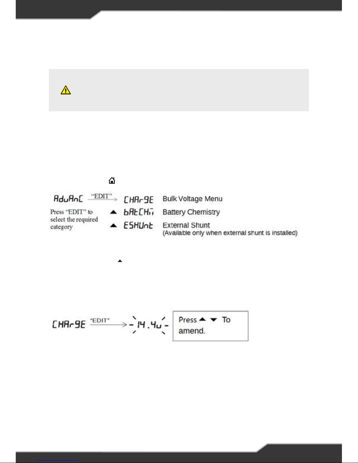
Press and release the button a few times until you see ADVANC
To exit menu, keep pressing the “Back” button until the home screen is seen.
WARNING
The advanced menu is reserved for technical personnel
only and available features vary with some versions of
the BatteryPlus35.
APPENDIX 1 : ADVANCED MENU
Incorrect use of this menu can over charge the battery and cause damage to
property and cause personal injury. If unsure, do not change the default values.
The advanced menu allows installers to fine tune the charging parameter, such as
bulk voltage, bulk time and float time.
Advanced Menu Entry
Press and hold the button until you see SETUP
Bulk Voltage
The bulk voltage is the maximum voltage at which the battery will be charged. This
voltage can be adjusted from 13.6V to 14.6V with increments of 0.1V.
To exit menu, keep pressing the “Back” button until the home screen is seen.
Page 48
48
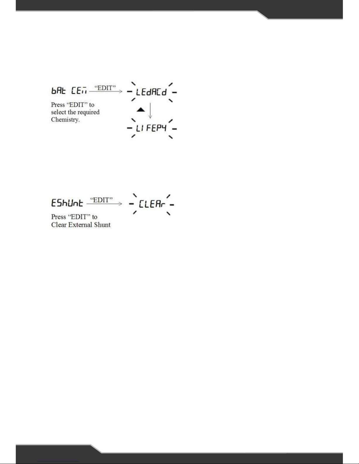
Battery Chemistry (BatteryPlus35HA only)
This menu can be used to select the battery chemistry. There are two types of
chemistries to choose from: Lead Acid and LiFePO4.
To exit menu, keep pressing the “Back” button until the home screen is seen.
External Shunt (Only if the external shunt is install)
The presence of the external shunt can be cleared in this menu item.
This menu item is used when the communication with the external shunt is lost.
If “Clear” is selected, the BatteryPlus35 will ignore the error of not detecting the
external shunt and behave as the external shunt is not installed.
Page 49
SYSTEM MANUAL
RVView
www.teambmpro.com
Page 50
50
INTRODUCTION
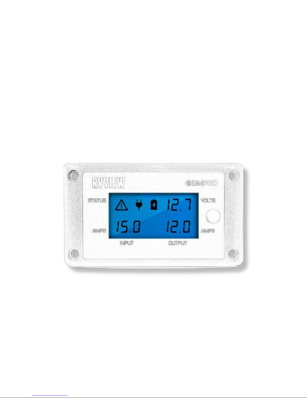
RVView monitors and displays vital battery information such as volts and amps,
charge/discharge status and details of the source input for your recreational vehicle
12V system.
RVView is permanently wired into the BatteryPlus35 in the recreational vehicle and
continuously monitors battery information, providing vital data at a glance using a
clear back-lit display.
Safety Precautions
Please read the Safety Precautions carefully before installing the unit.
Failure to observe these instructions properly may result in
property damage or personal injury, which may be serious
depending on the circumstances.
Refer to the installation section before operating. Correct installation is the most
critical factor in ensuring the safe use of the power supply. If every consideration
of these instructions has been satisfied the power supply will be safe to operate.
As this unit is powered by a communication cable it is critical that all connections
and cables are in a good and working order and properly connected.
Do not allow water or other liquids to enter the installation area.
CAUTION
Accessories
The following accessories are provided with RVView.
• RVView Unit
• RVView Manual
• 4 Mounting Screws
About RVView
The RVView is a display unit that connects to BatteryPlus35 and displays battery or
system information. Its backlit LCD displays information includes:
• System voltage
• Input and output current
• Battery charging and discharging indicator
• Power Source – Mains, Solar or Car
• Warning indicator
• Battery charge status
• Back-light which turns on for 30 seconds
Page 51
51
Name and Function of Parts
Warning Indicator
Input Current
Output Current
Backlight Button
System Voltage
Battery Status Indicator
Source Indicator
1
3
62
5
4
7
1
7 6
5
2
3
4
Page 52

52
OPERATION
RVView is designed to interface with BatteryPlus35. The functionality described
below assumes RVView has been correctly connected to BatteryPlus35.
The RVView will turn off if battery voltage is too low.
DESCRIPTION OF DISPLAY ELEMENTS
Warning Indicator
The warning symbol will be displayed
1. If one or more of the outputs on the BatteryPlus35 are shorted or overloaded.
To fix the issue check all wiring and appliances connected to the BatteryPlus35
outputs. Remove any faults found.
2. If the external shunt was installed and is no longer communicating the warning
icon is as follows:
The Warning Icon
Input Current
This is the total current provided by the BatteryPlus35 from any source to the
appliances and the battery, shown in Amps.
Example; if the battery is charging at 5 Amps and the appliances are consuming 10
Amps then the input current will display 15 Amps.
If no sources are available or no battery is installed this section is left blank.
Output Current
The output current is current provided by the system to the output appliances, shown
in Amps. This would display 10A in the above example.
Backlight Button
A single press of this button will turn the backlight on and will turn it off in 30 secs.
Repeated single presses will toggle the backlight on and off.
1
2
3
4
Page 53
53
System Voltage
This is the system voltage. If a battery is installed then this is the voltage across the
battery terminals. If no battery is installed then this is the voltage generated by the
BatteryPlus35.
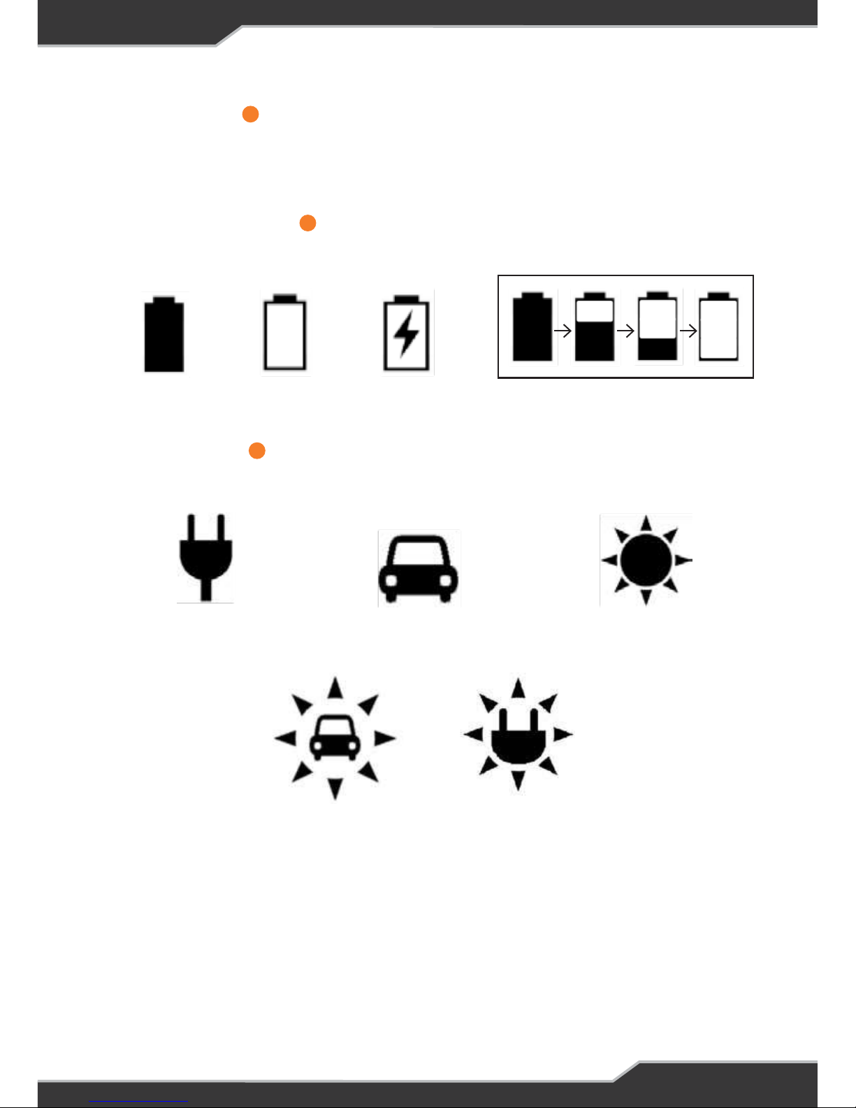
Battery Status Indicator
RVView indicates 4 different battery status.
Battery present
& is 100%
Battery is present
& NOT 100%
Battery is charging.
The BOLT inside the
symbol will be ashing
Battery is discharging.
The animation shows the discharging action.
Only AC Mains
is available
Only Auxiliary Source
is available
Only Solar is
available
Source Indicator
The RVView indicates if various sources are available, the follow are displayed
Solar and AC mains are
available at the same time
Solar and Auxiliary are
available at the same time
6
5
7
Page 54
54
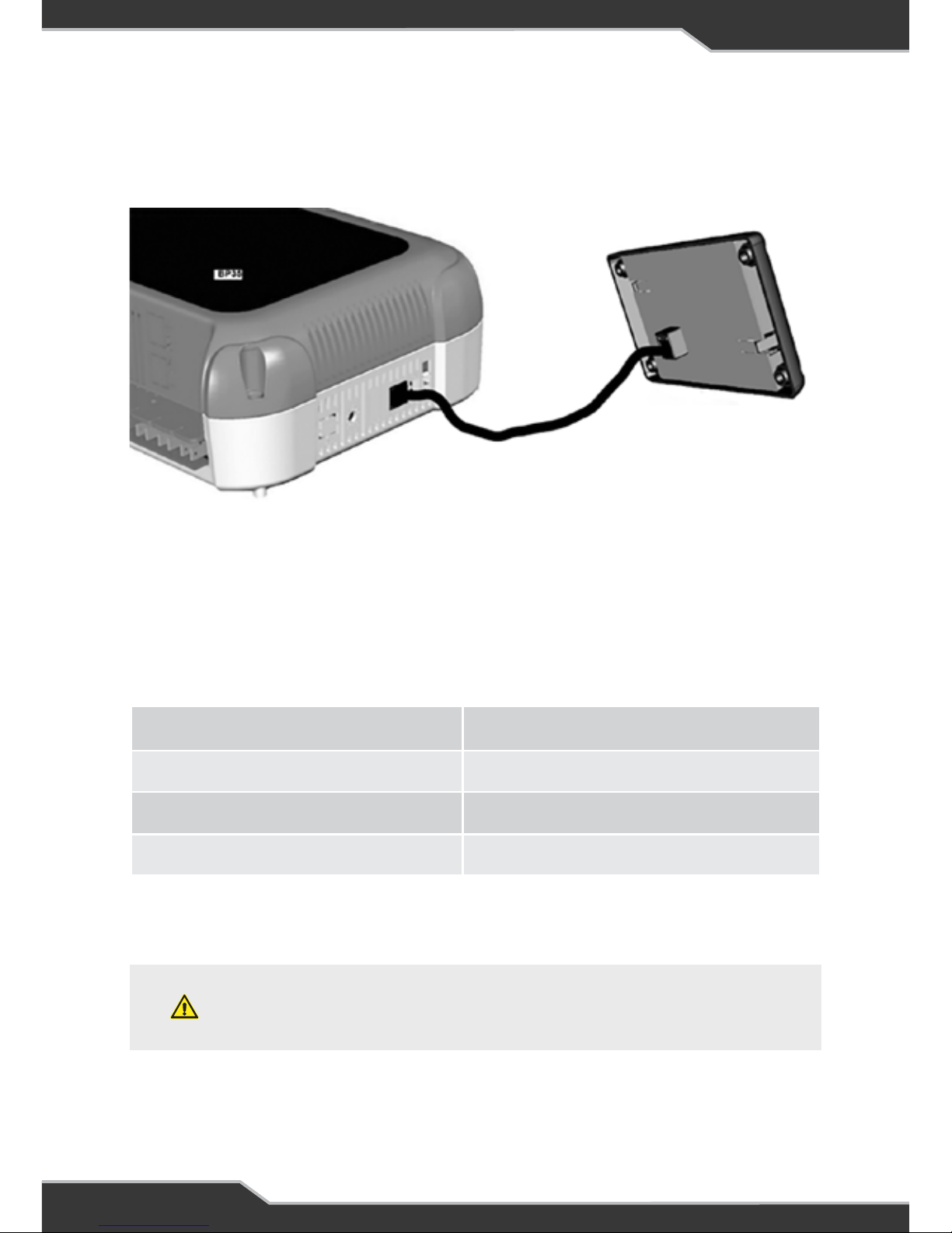
CONNECTORS
At the rear of RVView a data cable is used to connect it to the BatteryPlus35.
DATA Cable
SPECIFICATIONS
Input Voltage: 8 — 15 Vdc
Battery Drain: < 22 mA (backlight off)
Ambient Temperature: 0°C – 50°C
Size: 140 W x 80 H x 15.5 D
WARNING
DO NOT disassemble, modify, or repair the unit.
Doing so may result in electric shocks or fire.
Repairs and After-sales Service
Consult your “BMPRO by Setec” dealer. or visit teambmpro.com
AFTER-SALES SERVICE
SERVICING
There are no internal user serviceable parts
Page 55
55
TROUBLESHOOTING
Observation The RVView LCD is blank.
Solution The BatteryPlus35 will turn off the RVView if the battery
voltage is too low or if the isolation switch on BatteryPlus35
is shorted.
RVVIEW INSTALLATION INSTRUCTIONS
Personnel
Installation is to be carried out only by suitably qualified personnel.
Installation Environment
RVView should be installed indoors where it will not be subject to water or other
liquid spills or splashes.
Items Required For This Installation
1. The RVView Unit
2. The Data cable
3. 4 Mounting Screws
4. A 25mm hole saw
5. Power Drill
6. Philips Screw diver
Installation
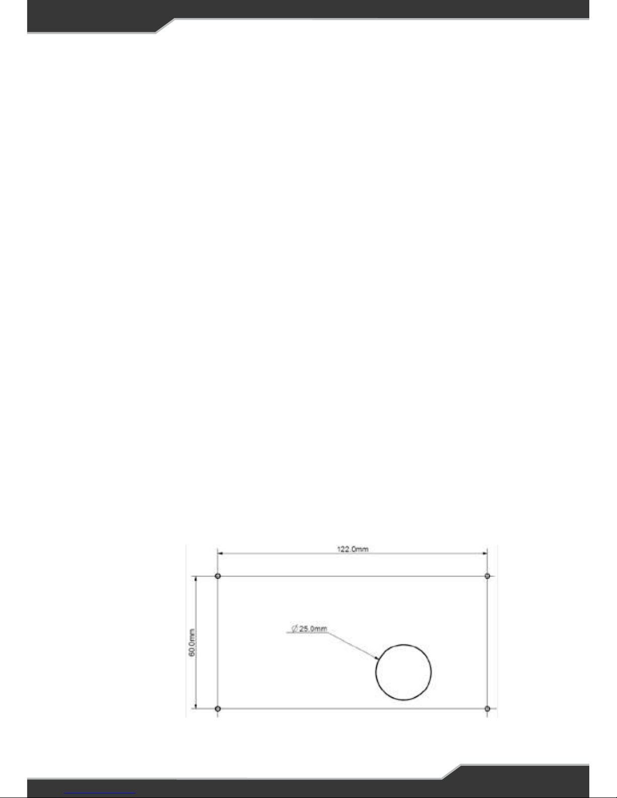
First drill a minimum 25mm hole in the wall to fit the data cable to the RVView,
as shown below:
Not to Scale
Page 56
56
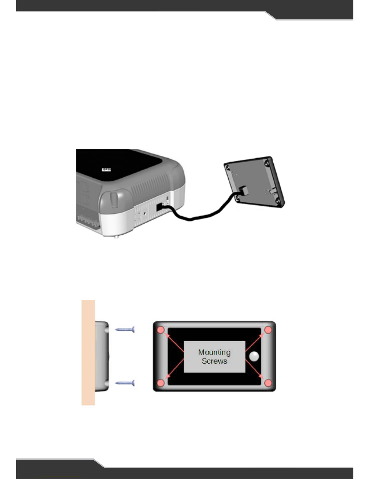
Connect the Data Cable
Connect the BatteryPlus35 to the RVView using the data cable, through the 25mm
hole in the wall.
Mount the RVView
Using the screws provided, mount the RVView to the wall. Pre-drill the mounting
holes if required.
After fixing RVView to the wall, remove clear protective plastic from the front cover.
Setting the Battery Capacity
If a 100AH battery is installed proceed to next step
“CONNECT THE DATA CABLE”
If a battery/battery bank of more than 100AH is to be installed, a Trek is needed to
set the battery capacity. Go to “SET THE BATTERY CAPACITY USING A Trek” first.
Page 57
57
Set the Battery Capacity Using a Trek
Follow these steps if you are installing a battery/battery bank of more than 100AH.
2. Connect the BatteryPlus35 to the battery
3. Then connect the Trek to the BatteryPlus35 using the DATA Cable
4. Notice that the Trek will turn on
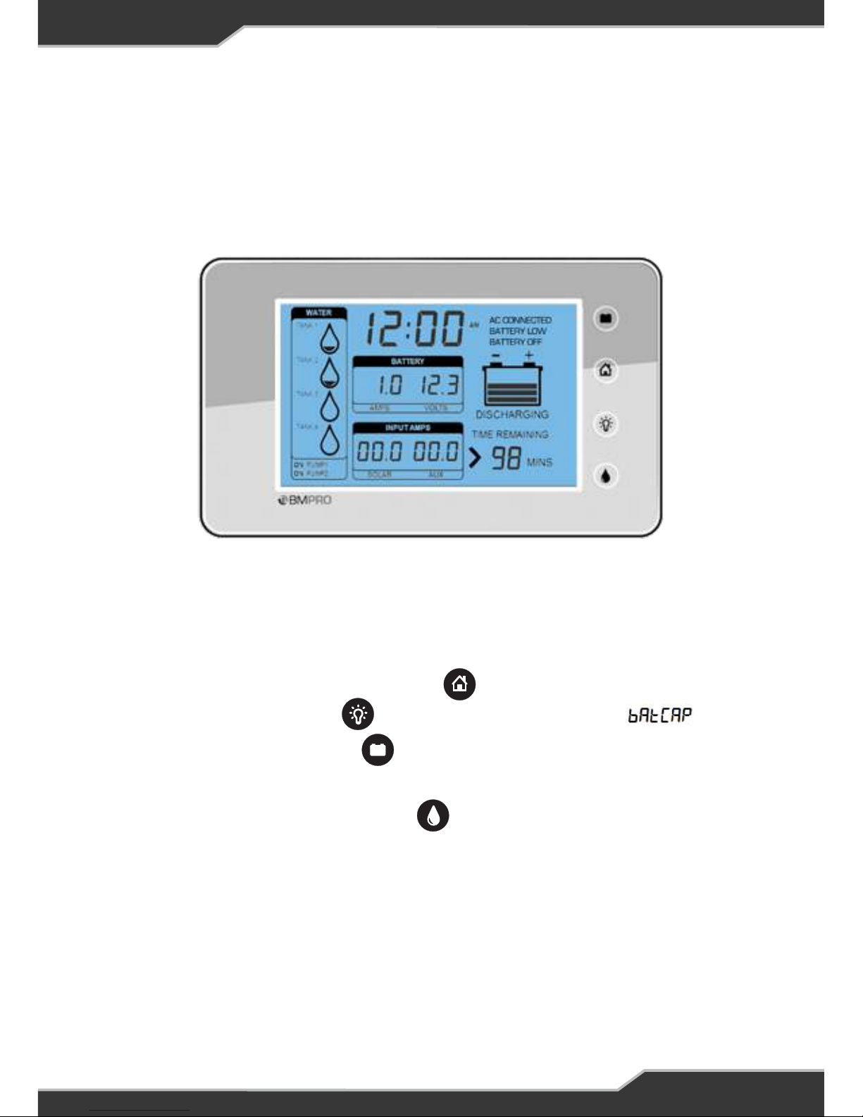
5. Next press and hold, the “HOME button” until the Setup is seen
6. Next press the “UP button” until the battery capacity is seen
7. Next press the “EDIT button” the capacity value will start to blink
8. Press the “UP button” to set your desired battery capacity
9. Once done, press the “BACK button” a few times to reach the Home screen
10. Finally disconnect the Trek and connect the RVView to the Data cable
11. Go to “CONNECT THE DATA CABLE”
1. First obatin a Trek Unit (Version 2E or above). Speak to your distributor or a
BMPRO team member.
Page 58

58
WARRANTY TERMS AND CONDITIONS
Registering your BMPRO by Setec product is an important step to ensure that you receive all
of the benefits you are entitled to. Please visit www.teambmpro.com to complete the online
registration form for your new product today.
BMPRO by Setec goods come with guarantees that cannot be excluded under Australian
Consumer Law. You are entitled to a replacement or refund for major failure and for
compensation for any reasonably foreseeable loss or damage. You are entitled to have the
goods repaired or replaced if the goods fail to be of acceptable quality and the failure does not
amount to a major failure. The benefits under this Warranty are in addition to your other rights
and remedies under a law in relation to the goods to which this Warranty relates (the Australian
Consumer Law).
Setec, as the manufacturer of BMPRO by Setec goods warrants products against defects for
a period of two years, commencing from the original date of purchase. Proof of purchase is
required before you can make a claim under this warranty.
HOW TO PROTECT YOUR RIGHTS UNDER THIS WARRANTY: The BatteryPlus35, Trek and
RVView are designed to be installed by a suitably qualified installer. You or your installer should
carefully inspect the products before installation for any visible manufacturing defects. We
accept no responsibility in addition to our consumer guarantee obligations where a product has
been installed incorrectly.
This warranty does not extend to product failures or defects caused by, or associated with,
but not limited to; failure to install or maintain correctly, unsuitable physical or operating
environment, accident, acts of God, hazard, misuse, unauthorised repair, modification or
alteration, natural disaster, corrosive environment, insect or vermin infestation and failure to
comply with any additional instructions supplied with the product.
Setec may seek reimbursement of any costs incurred by them when a product is found to be
in proper working order or damaged as a result of one or more of the warranty exclusions
mentioned in point 4 of this statement.
To enquire or make a claim under this warranty, please follow these steps:
a. Prior to returning a BMPRO by Setec product, please email [email protected]
to obtain a Return Material Authorisation (RMA) number
b. Package and send the product to: BMPRO by Setec Warranty Department,
19 Henderson Road, Knoxfield, VIC 3180.
Please mark RMA details on the outside of the packaging
c. Please ensure the package also includes: a copy of the proof of purchase, a
detailed description of the fault and your contact details including phone
number and return address
Setec will not be liable for any costs, charges or expenses incurred in the process of returning a
product in order to initiate a warranty claim
Page 59

Page 60

SWITCH OFF. POWER UP.
BMPRO A Setec Brand
www.teambmpro.com
 Loading...