


Air Heater Manuals
User/Installation/Servicing
BMM Heaters Ltd
1 Copeland Court
Forest Grove
Middlesbrough
TS2 1RN
Tel:01642 240700
Fax:01642 240708
Sales@bmmheaters.co.uk
1

BMM HEATERS REFERENCES
Heater Models Description
BMG Horizontal Heater for ducted or AHU
applications suitable for natural gas.
BMVG Vertical heater for ducted or AHU applications
suitable for natural gas.
BMGVF Free standing nozzle head heater with force
draught gas burner.
BMGDF Free standing ducted heater with force draught
gas burner.
BMGF Horizontal ducted heater with force draught gas
burner.
BMGDD Downward discharge heater with force draught
gas burner.
2

CONTENTS PAGE
DESCRIPTION
Section 1: Introduction…………………………………………. 4
Section 2: Heater Safety………………………………………… 5
Section 3: Installers Responsibilities…………………………… 5
Section 4: Specifications………………………………………… 6
Section 5: Heater Installation & Clearances…………………... 7
Section 6: Air supply…………………………………………….. 9
Section 7: Overheat Protection Device…………………………. 10
Section 8: Flue System…………………………………………… 11
Section 9: Ventilation Requirements……………………………. 16
Section10: Gas Piping……………………………………………. 17
Section 11: Condensate Drains………………………………….. 19
Section 12: Electrical Connections……………………………… 19
Section 13: Heater Controls……………………………………... 21
Section 14: Commissioning……………………………………… 23
Section 15: Servicing…………………………………………….. 32
Section 16: Removal and Replacement of Parts……………….. 37
Section 17: Spare Parts………………………………………….. 39
Section 18: Troubleshooting…………………………………….. 40
Section 19: Users Manual………………………………………... 41
Model:
Serial Number:
3

Section 1: Introduction
The instructions refer to appliances designed to operate in the UK and
Ireland.
Appliances designed for other countries can be provided on request.
This appliance must be installed in accordance with the local and national
codes in force and used only in a sufficiently ventilated space, as specified in
these instructions.
Before installation, check that the local gas distribution systems, nature of gas
and pressure, and adjustment of the appliance are compatible.
Indirect Fired
The term ‘Indirect Fired’ indicates that the products of combustion are kept
isolated from the main supply air stream. The burner fires into a combustion
chamber, the resultant products of combustion are directed into a heat exchanger
and from there to an external flue, which discharges into the atmosphere.
Factory Test
All heaters produced by BMM Heaters Ltd will be subjected to various tests
before they are dispatched. Each heater is individual so the data will differ
between each unit. The relevant data can be found on the data plate attached to the
heater.
External Heaters
The construction of the unit will consist of double skin panels and be fully water
proof; the burner compartment will be adequately ventilated via two combustion
air grills.
Burner and Fuel
These appliances will be fitted with either a Force Induced Natural Gas Burner or
Pressure Jet Oil Burner.
Burner Type
BMM Heaters Ltd use two main manufacturers; Reillo or Weishaupt, which are
available for on/off, high/low or fully modulating appliances.
Oil Burners are available for on/off or high/low control.
4

Section 2: Heater Safety
The Installation of this appliance must be done by a registered installer/contractor
suitably qualified in the installation and service of gas fired heating equipment.
WARNING!
Improper installation, adjustment, alteration, service or maintenance can
result in death, injury or property damage. Read the installation, operation
and service manual thoroughly before installing or servicing this appliance.
Note:
To Installer: Please take the time to read and understand theses instructions prior
to any work servicing or installing this appliance.
Installers must leave a copy of this manual with the end user/owner.
To Owner: This manual must be kept in a safe place in order to provide necessary
information for service engineers at a later date.
Section 3: Installers Responsibilities
♦ To install the heater, as well as the gas and electrical supplies, in
accordance with applicable specifications and codes. BMM Heaters
recommends the installer contact a local Building Inspector, Fire Officer or
Insurance Company for guidance.
♦ To use the information given in the manual together with the local and
national codes to perform the installation.
♦ To install the heater in accordance with the Clearances to Combustibles of
this heater.
♦ To plan for the installation of supports, flues and air intakes.
♦ To provide access to burners for servicing.
♦ To provide the owner with a copy of this installation, commissioning,
operation and service manual.
♦ To never use heater as support for ladder.
♦ To ensure that there is sufficient ventilation in the area to comply with the
requirements of all relevant local and national codes.
5

Section 4: General Technical Table 1
Model
12 .37 .75 15 12 0.36 1.5 154 150 75 66
15 .37 .75 19 15 0.432 1.8 154 150 75 66
18 .37 .75 23 18 0.44 2.2 154 150 75 66
23 .47 .75 30 23 0.7 2.9 154 150 75 66
30 .75 .75 38 30 0.94 3.9 154 150 75 66
44 .82 1.55 57 44 1.08 5.4 154 150 207 192
59 1.13 1.55 75 59 1.75 7.3 154 150 207 192
88 1.55 1.55 113 88 2.62 10.9 154 150 207 192
117 2.11 2.58 150 117 3.48 14.5 204 200 246 228
Min
Air
flow
m³/sec
Max
Air
flow
m³/sec
Heat
Input
kW
Heat
Output
kW
Max Start
Gas Rate
m³/hr
Gas
Flow
Rate
m³/hr
Flue
Spigot
Nominal
Ø mm
Flue
Size
Ø mm
Weights
External
Heater
Kg
Weights
Internal
Heater
Kg
147 2.58 2.58 188 147 4.18 17.4 204 200 246 228
176 3.19 5.17 225 176 5.23 21.8 204 200 420 384
205 3.75 5.17 263 205 6.1 25.4 254 250 420 384
235 4.23 5.17 300 235 6.98 29.1 254 250 420 384
264 4.75 5.17 338 264 7.85 32.7 254 250 420 384
293 5.17 5.17 376 293 8.71 36.3 254 250 420 384
352 6.23 6.23 451 352 10.32 43 304 300 1704 1364
440 8.46 10.34 537 440 13.08 54.5 304 300 1704 1364
513 9.40 10.34 658 513 15.24 63.5 304 300 1704 1364
586 10.34 10.34 752 586 17.42 72.6 354 350 1704 1364
733 13 16.53 939 733 19.34 80.6 406 400 2304 2160
880 15.35 16.53 1127 880 26.14 108.9 406 400 2304 2160
952 16.53 16.53 1221 952 28.32 118 406 400 2304 2160
Each appliance has been range rated; burner pressures can be found on the data
plate and the burner pressure once commissioned must be entered in the actual.
6
Section 5: Heater Installation
Before installation, check that the local distribution conditions, nature of gas
pressure and adjustment of the appliance are compatible.
The air heater must be installed in accordance with the rules in force and the
relevant requirements of any fire regulations or insurance company’s requirements
appertaining to the area in which the heater is located, particularly where special
risks are involved, such as areas where petrol vehicles are housed, where cellulose
spraying is carried out, in wood working departments etc.
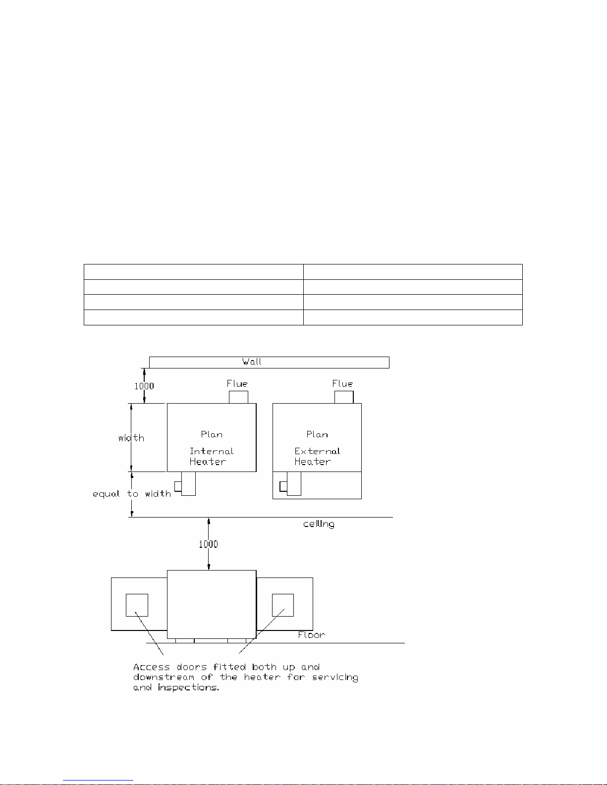
Clearances and Positioning:
The following clearances for installation and servicing must be observed.
To the front Equal to the depth of the heater.
To the rear 1.0m
To at least one side 1.0m
Above the heater 1.0m
Clearances fig.1
7

Clearances
A minimum of 500mm upstream and downstream must be allowed for, due to the
radiant heat. Filters must be fireproof, if fitted and a motor shield is required over
the main supply fan motor if directly in front of the heater.
When installing the heater, minimum clearance is required around the heater.
If the heater is to be fitted at a height, then the structure of the gantry must be
capable of the heaters weight (which can be found in section 4, table 1), also a safe
working platform and access must be allowed for; to enable easy and safe working
access.
Note: The front of the heater is the side on which the burner is fastened.
When designing a system, allowance must be made so equipment can be serviced
after installation and for the fitting of any spares, which may be required. The
BMG is designed to be installed within an Air Handling Unit or ductwork.
The appliance is designed to work in a maximum ambient temperature of 40°c.
The Air Heaters are mounted direct on the floor and do not need any fixing. The
base on which the heater is positioned should not be less than 150mm (6 inches)
thick and must be constructed of non-combustible material.
Any combustible material adjacent to the heater and the flue system must be
placed or shielded as to ensure that its temperature does not exceed 65ºC.
WARNING!
No air heater shall be installed where there is a foreseeable risk of flammable
particles, gases, vapours or corrosion inducing gases or vapours being drawn
into either the heated air stream or the air for combustion. In such cases
installation may only proceed if the air to be heated and the air for
combustion are ducted to the heater from an uncontaminated source,
preferably outside the building.
If this heater is to be suspended then weight in table 1 in section 4 must be taken
into account.
8

Section 6: Air Supply
Ductwork
All delivery and return air ducts, including air filters, jointing and any insulation
or lining must be constructed entirely of materials, which will not contribute to a
fire, are of adequate strength and dimensionally stable for the maximum internal
and external temperatures to which they are to be exposed during commissioning
and normal operation. In the selection of materials, account must be taken of the
working environment and the air temperatures which will result when the overheat
limit thermostat is being commissioned. Where inter-joint spaces are used as duct
routes, they should be suitably lined with fire-resisting material.
A full and unobstructed return air path to the air heater must be provided.
If the air heater is to be installed in a plant room, the return air and warm air
discharge arrangements must be such as to avoid interference with the operation of
the flue by the air circulation fan. The return air intake and the warm air outlet(s)
should therefore be fully ducted, in the plant room, to and from the heater,
respectively. The openings in the structure of the plant room through which the
ducting passes must be fire stopped.
In addition, where there is a risk of combustible material being placed close to the
warm air outlets, suitable barrier rails should be provided to prevent any
combustible material being within 900mm (3 ft) of the outlets.
Air flow
It is essential that the correct amount of air is provided through the heater and
should be evenly distributed when entering the heater. All pressure
calculations/resistances for air are ambient with the Heater in the ‘off’ position.
Adjustable by pass plates
BMG models fitted into larger cabinets for internal or external use should be fitted
with adjustable air balancing plates or a simple restriction damper. If the work is
not going to be carried out by BMM Heaters Ltd then we recommend that the
installer ensures that it can be altered to give guaranteed minimum equal air over
the combustion chamber/heat exchanger (see minimum and maximum air flow
volumes in section 4 table 1).
9
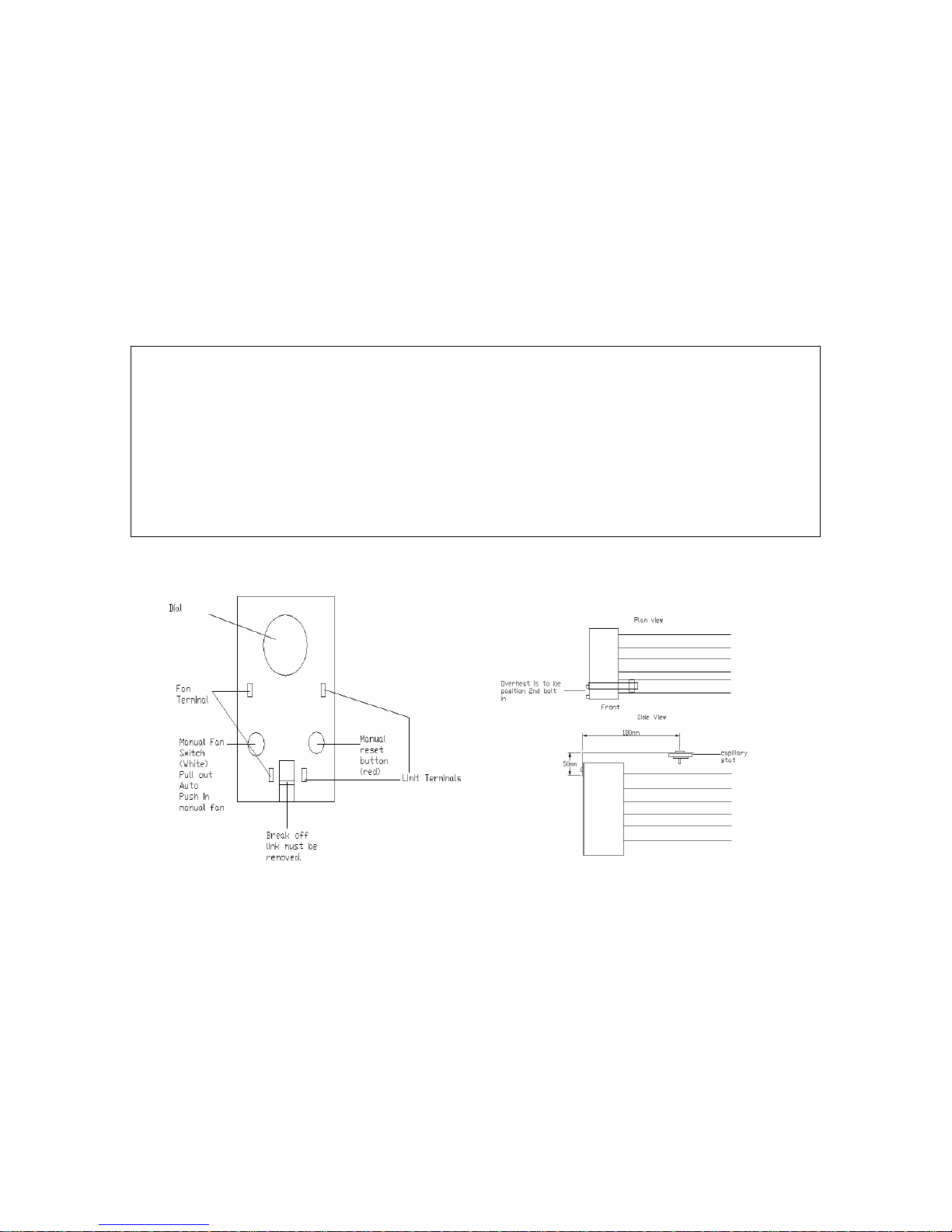
Section 7: Overheat Protection Device
Overheat protection is fitted in case the air flow falls below the minimum
necessary for safe operation of the heater, which may be caused by failure of the
supply fan motor or belt failure, dirty filters or inlet damper failure. If the air flow
falls too low, the high limit will trip out and will require manually resetting. If this
happens on a regular basis it must be investigated by a competent registered
engineer as this could cause serious damage to the heater.
WARNING!
If the heater has a Honeywell combined thermostat installed then the jumper
link must be removed from the replacement thermostat.
Heat exchanger damage may be the result.
Failure to follow these instructions can result in death, injury, property
damage or product damage.
Honeywell overheat stat Fig 2 Overheat Position Fig 3
Ensure that the fan and limit settings are as follows:Fan On 35ºc
Fan Off 25 ºc
Limit 20 ºc above normal running temperature no greater than 100 ºc
10

Section 8: Flue System
The flue system must be made to the following specifications:
a) Mechanically robust.
b) Resistant to internal and external corrosion.
c) Non-combustible and durable under the conditions to which they are to be
subjected.
d) Stainless steel flue is recommended.
Design
When designing a flue system for the appliance the designer must take into
account the following points.
a) The flue gases exiting the appliance can be as great as 350 ºc and as low as
70 ºc on modulating burners.
b) Prevention of condensation within the flue and the management of drainage
from the flue; for example the use of twin wall flue will minimise the
condensation.
c) Flue must be a type acceptable to current standards.
d) Facilities should be made for the disconnection of the flue from the heater
to aid servicing and inspection.
e) This appliance does not require a draught diverter.
f) BMM Heaters recommend that a 90º Tee condensate piece is connected
directly onto the heater spigot, from this point the flue must then rise
vertically with no horizontal runs of flue pipe or 90º bends. If there is an
unavoidable obstruction then the use of 45º bends will be permitted.
(Please contact BMM Heaters if more that two 45º bends are used).
g) The flue should terminate in a freely exposed position and must be situated
as to prevent the products of combustion entering the building via any
opening.
h) A Flue terminal must be fitted.
i) The flue installation must be designed to the latest gas regulations and any
local environmental standards.
j) Where a flue passes through a combustible roof, ceiling or floor, the flue
pipe should be surrounded with a metal sleeve, the size of which should be
sufficient to provide a space not less than 25mm between the flue pipe and
the sleeve when positioned.
Note! Flue connection sizes can be found in section 4 table 1
11

Minimum and maximum flue heights
Internal: 600mm above the apex is the minimum height above the building if
within 1.5 metres of the surface, see drawings Figure 1 & 2.
Maximum height is no more than 25 metres, if this exceeded please
consult BMM Heaters or consideration should be given for a fan
assisted flue.
External: Minimum flue height is 1 metre above appliance roof.
Maximum height is no more than 25 metres, if this exceeded please
consult BMM Heaters or consideration should be given for a fan
assisted flue.
Flue terminal
A flue terminal (must be approved) needs to provide an extraction effect under
virtually all wind conditions, the free area of outlet openings should be at least
twice the nominal area of the flue. Outlet openings should be provided preferably
all round, or at least on opposite sides.
It is important for the terminal of an individual open flue system to be located so
that it is not likely to be subjected to wind pressures which could restrict or reverse
the flow of combustion products through the flue.
The ideal position is above the highest point on the roof. It is absolutely essential
that the terminal is positioned outside the building so that it is freely exposed to
any wind and is not shielded by any roof structure or object to such a degree that
they create undesirable pressure regions around the terminal.
12
Preferred positions are:
- At or above the ridge of a pitched roof by means of a roof terminal.
- Above the intersection with a pitched roof.
The pitch or angle of the roof will determine the required flue height from the base
of the terminal. See Table 2 below:
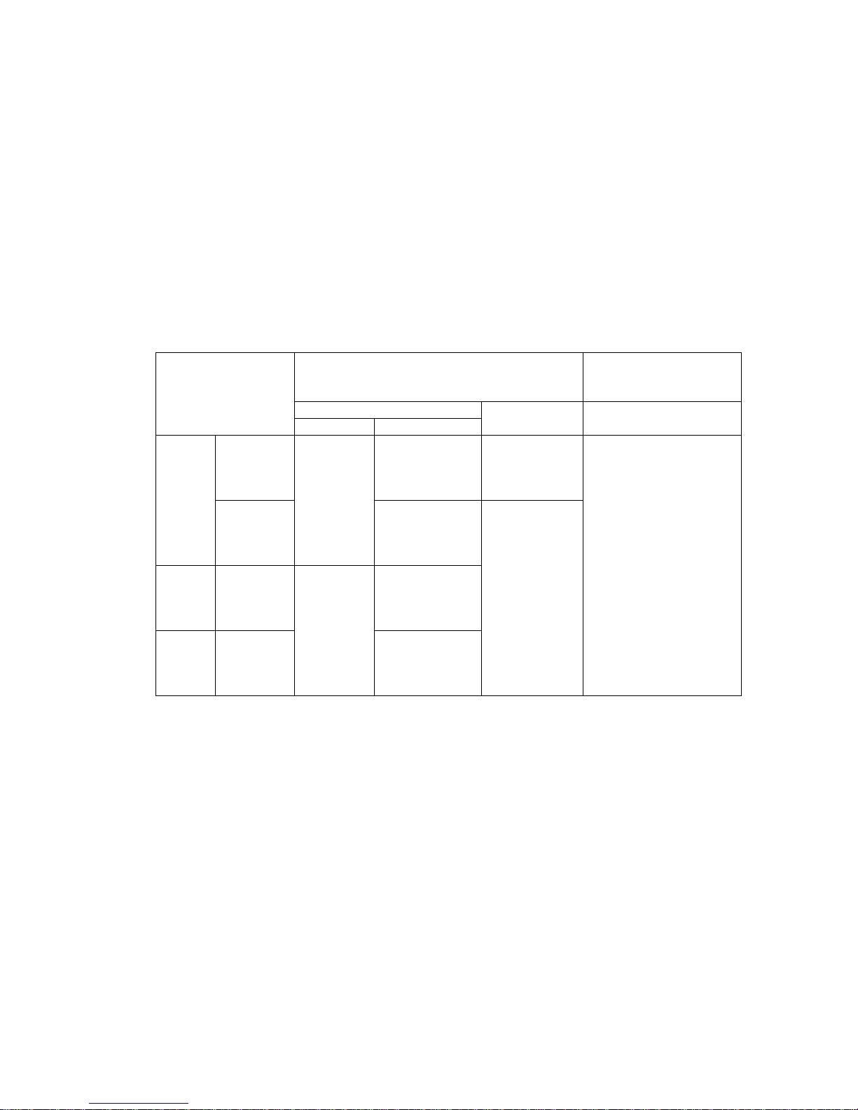
Table 2
RECOMMENDED LOCATIONS OF ROOF TERMINALS:
Location not within 1.5m of a vertical surface*
Type of roof
on the roof
Internal route
Pitch
Pitched
exceeding
45°
Flat With
Without
Pitch not
exceeding
45°
parapet
parapet
On ridge Not on ridge
At or
above roof
level (see
figure 4)
Not
applicable
1m above flue/
roof
intersection (see
figure 3)
600mm above
flue/roof
intersection (see
figure 4)
600mm above
flue roof
intersection (see
figure 6)+
250mm above
flue/roof
intersection (see
figure 10)
External route Internal route
See figure 3
The base of the
terminal to be
600mm above
the level of the
adjacent roof
edge (see
figures 1, 6
and 10)
Location within 1.5m of
a vertical surface* of a
structure on the roof
External route
The base of the terminal
to be 600mm above the
level of the top of the
structure (see figures 2,
5, 9 and 11)
*For example: a chimney stack dormer window; tank room; lift motor room;
parapet, etc.
+When the flue outlet is at a horizontal distance greater than 10 times the
height of the parapet or structure, the terminal outlet height need be only
250mm above the roof.
13

Not Less
m
than
1000 mm
Not less
than
600 mm
Not less
than
1000mm
Not greater than 45°
Fig 1. Pitched roof, not greater than 45°
Greater than 45°
Fig 3. Pitched roof, exceeding 45°
Not less than 600 mm
Dormer
window
Terminals must not be positioned
within 1.5m of the wall surface
Not less than
600 mm
Not less than
1000 mm
Not less than
600 mm
Fig 4. Pitch roof, internal route, pitch not
Fig 5. Pitch roof, chimney within
1.5 m from dormer window
measured horizontally
Less than
1500 m
Dormer
window
Fig 2. Pitched roof, within
1.5 m of a structure on roof
Termination
on ridge
Less than 45°
exceeding 45° and ridge termination
14
Not
Less
than
600mm

m
m
m
Not less than
600 m
Fig 6. Flat roof, with parapet
Structure
Not less
than
600 mm
h
2
Less than 10 h
Fig 7. Flat roof, envelope method
h
2
Structure
Greater than 10 h
Not less than
600 m
Fig 8. Flat roof, flue outlet more than 10 heights (h)
Less than
1500 m
Parapet
Fig 9. Flat roof, with flue close to parapet
Less
than
1500
mm
Parapet
2
2
away from all structures
Not less
than 600
mm
Greater than 1500 mm
250 mm
Greater than 10 h
Structure
Not less than
600 mm
Structure
1
Not less
than 600
Fig 10. Flat roof, with no parapet
Fig 11. Flat roof, with structure close
to flue outlet
Structure
h
h
Not less
than
250 mm
15

Section 9: Ventilation Requirements
Where the heater is to be installed in a plant room, the heater requires the plant room
housing to have permanent air vents communicating directly with the outside air, at a
high level and at a low level. Where communication with the outside air is possible
only by means of high level air vents, ducting down to floor level for the lower
vent(s) should be used. Air vents should have negligible resistance and must not be
sited in any position where they are likely to be easily blocked or flooded, or in any
position adjacent to an extraction system, which is carrying flammable vapour.
Grilles or louvers should be designed so that high velocity air streams do not occur
within the plant room.
The ventilation should be installed to in accordance with local and national codes.
Ventilation Requirements:
The space in which the heater is situated must be adequately ventilated, see below for
the minimum ventilation area at low and high levels.
Low Level:
540cm² plus 4.5cm² per kW after 60kw.
High Level:
270cm² plus 2.25cm² per kW after 60kw
16

Section 10: Gas Piping
All Gas Pipe-work to the appliance should be installed in accordance with
current regulations, local and national codes and must be connected with an
acceptable gas isolation valve and union, so that the burner maybe removed
to aid servicing and inspection of the burner.
Size and Connection
The following considerations are to be taken into account:
a) Pipe work smaller than the inlet gas connection should not be used.
b) The gas supply pipe is adequately sized to carry correct volume of gas from
the gas meter to the heater(s).
c) The heat input and gas flow rates for each heater can be found in section 4
table 1 to aid in the design of gas supply pipe work.
d) All gas pipe work and electrical connections must be adequately supported
and must not support any of the heaters weight or rely on the strength of the
burner gas pipe work.
e) Unless the heater is suspended or movement is apparent, the BMM Heater
must be connected with medium, heavy or copper pipe; otherwise the use
of an approved flexible connection between the isolating valve and the
heater can be used. We recommend that the flexi hose is one size bigger
than the heater connection to reduce any pressure loss.
The minimum inlet gas pressure for natural gas should be 20 mbar.
Please note: We require a minimum of 17.5mbar at the inlet when running and a
maximum of 75mbar, if this is exceeded then a governor must be fitted.
Important: The complete installation must be purged and tested for gas
soundness in accordance with local, national codes and a registered engineer.
17

Gas Connection Size
Model Weishaupt Burner Riello Burner
12
15
18
23
30
44
59
88
117
147
176
205
235
264
293
352
440
513
586
733
880
952
½" BSP ½" BSP
½" BSP ½" BSP
½" BSP ½" BSP
½" BSP ½" BSP
½" BSP ½" BSP
¾" BSP ½" BSP
¾" BSP ¾" BSP
¾" BSP ¾" BSP
1" BSP ¾" BSP
1" BSP ¾" BSP
1½" BSP 1" BSP
1½" BSP 1" BSP
1½" BSP 1¼" BSP
1½" BSP 1¼" BSP
1½" BSP 1¼" BSP
2" BSP 2" BSP
2" BSP 2" BSP
2" BSP 2" BSP
2" BSP 2" BSP
2" BSP 2" BSP
2" BSP 2" BSP
2" BSP 2" BSP
Further Information regarding pipe work to the burner can be found in the
burner manual attached to this document.
18

Section 11: Condensate Drains
On models where larger turndowns are required, there will be a 1” BSP
condensation drain, which must have a trap fitted and then pipe/drain
accordingly (by others). The condensate pipe work must not be installed
below 1” BSP.
WARNING!
Do not use plastic connections, as the temperature may be high at the
outlet to the drain. Copper pipe must not be used.
Important
Condensing heaters may be subject to local regulations with respect to the
discharge of condensate.
Section 12: Electrical Connections
All external wiring must be in accordance with current IEE Regulations and
local regulation which apply.
The method of connection to the mains electricity supply should allow
complete electrical isolation of the heater and the supply should serve the
heater only. The mains isolator should be provided adjacent to the heater in
an easily accessible position. The isolator must have contact separation of at
least 3 mm on all poles.
The electric and controls terminations are located on the front of the Heater
housed in an interface panel. All heaters are compatible for inter-facing with
building management systems and 0-10v DC is required as standard on
Modulating heaters.
All wiring and control cables must be ran in conduit and correct size glands
used etc.
All appliances must be earthed.
Each heater manufacture is individually made to suit the customer so a
dedicated circuit will be attached to this manual. BMM Heaters will also
attach a circuit within the interface panel.
19

Table 3: Electrical Data
Model Motor size
Three phase
18 750w 550w 10 Amps 5 Amps 10 Amps
23 750w 550w 10 Amps 5 Amps 10 Amps
30 750w 550w 10 Amps 5 Amps 10 Amps
44 750w 550w 10 Amps 5 Amps 10 Amps
59 750w 550w 10 Amps 5 Amps 10 Amps
88 750w 750w 10 Amps 5 Amps 10 Amps
117 1.5kw N/A 15 Amps 5 Amps 15 Amps
147 2.2kw N/A 15 Amps 5 Amps 15 Amps
176 5.5kw N/A 20 Amps 5 Amps 30 Amps
205 5.5kw N/A 20 Amps 5 Amps 30 Amps
235 7.5kw N/A 30 Amps 5 Amps 30 Amps
293 7.5kw N/A 30 Amps 5 Amps 30 Amps
440 2 x 5.5kw N/A 30 Amps 5 Amps 30 Amps
513 2 x 7.5kw N/A 30 Amps 5 Amps 30 Amps
586 2 x 7.5kw N/A 30 Amps 5 Amps 30 Amps
733 Special Requirements On application - 880 Special Requirements On application - 952 Special Requirements On application - -
Motor size
Single phase
Motor rated
supply fuse
(Three phase)
Control Fuse Motor rated
supply fuse
(Single Phase)
Controls: BMM Heaters can supply controls for these heaters upon request.
Please confirm with us the type of controls prior to connecting to check
compatibility.
The Burner wiring diagrams can be found in the burner supplement provided with
this manual.
Note: All heaters have been electrically tested at BMM Heaters factory.
20

Section 13: Heater Controls
The heater can be used with most Building Management Systems.
2:1 Turndown Burner:
The heater interface panel connections:
(a). 240v & N supply
(b). T1 & T2 is the enable, T1 & T2 must break when up to a
temperature, all interlocks to be wired in series with T1 & T2. (The
burner must be interlocked with the supply fan).
(c). T6 - is 10v DC signal for modulation
(d). T7 - 24 volts AC supply for modulating, please note the 24 volts
transformer is in our panel, please advise if you are using external 24
volts.
(e) T8 - 0 volts
(f) T5 - 240v burner lockout indication if required.
Please supply 15 minutes supply fan over run on burner shutdown
If you require any further information or you have any special requirements
please do not hesitate to contact our Technical Department.
For ON/OFF Control Only, Omit sections C, D & E
21

4:1 Turndown Burner:
The heater interface panel connections:
(a). 240v & N supply
(a) T1 & T 2 is the enable, T1 & T2 must break when up to temperature, all
interlocks to be wired in series with T1 & T2. (The burner must be
interlocked with the supply fan).
(b) T6 – is 10v DC signal for modulation.
(d) T8 – 0 volts.
(e) T5 – 240v burner lockout indication if required.
Please supply 15 minutes supply fan over run on burner shutdown.
If you require any further information or you have any special requirements,
please do not hesitate to contact our Technical Department.
WARNING!
Electrical Shock Hazard
Use extreme caution while working on this appliance.
Failure to follow these instructions can result in death or electric shock.
Only competent engineer should carry out work on this appliance.
22

Section 14: Commissioning.
Commissioning ON/OFF
COMMISSIONING MUST BE CARRIED OUT BY A COMPETENT
REGISTERED ENGINEER (CORGI), ALSO TO BE USED WITH BURNER
COMMISSIONING DETAIL SEE BURNER INSERT.
1. Visually check full system to see if it is in accordance with our manual and to
current / CORGI legislation and IEE regulations and to this manual.
2. Check combustion air is adequate in plant room or surrounding area.
3. Check contractors electrical wiring is correct & terminated tight and fuse
ratings are correct.
4. Ensure that the gas pipe work is sized correctly and relative documents for
soundness & purging are available. It is the responsibility of the
commissioning engineer to check for soundness from the main inlet to
servicing stop tap on inlet of valve.
5. Ensure that the inlet gas pressure is no greater than 75mb static and no less
than 17.5mb running.
6. Make sure that all dampers are set and diffuser outlets are open to give correct
air flow and that the correct number of air by-pass blades have been removed
to by-pass the air in excess of our maximum amount of air through our heater,
which can be found in Section ‘Minimum and Maximum Air Volumes’ of this
Manual.
7. Check with the controls engineer that he has an interlock with the supply fan &
burner so that the burner can not run without the supply fan e.g. Air pressure
switch across supply fan in series with our Enable circuit between T1 & T2.
The controls must keep the supply fans running on for 15 minutes after burner
shut down, on a shut down condition. The terminals 1 & 2 are also used to wire
stats and time switches in series to switch the burner on and off.
8. Make sure that the stat, which is wired between terminals 1 & 2, is closed and
turn the main gas on to make the gas pressure switch and turn the
commissioning stop tap off. Switch the burner on, the burner should run
through its cycle and after the ignition spark goes out the burner should lockout
on flame failure on the burner control box.
23

9. Before opening the commissioning stop tap ensure that the burner air damper is
open. The main valve has to be disconnected and the pilot is to be left
connected, then open the commissioning tap and switch the burner on. The
burner should go through its sequence and fire but stay on. At this point in
time you have to check the start gas rate which should be no greater than 20%
of the total output. This is preset in the factory and should be checked.
10. When satisfied with the pilot pressure, switch the burner off and reconnect the
main valve, turn the main gas valve and turn the gas valve throttle to minimum
and switch the burner back on. Now the burner should fire and go to full fire,
then set the head pressure in accordance to the rating plate. The governor must
be throttled down until it takes control of the head pressure and left there. The
main gas valve throttle can be locked in to position when the gas head pressure
is set. When you are satisfied with the gas settings then the CPI switch requires
setting, on the SKP valves they are integral, which are factory set. For further
information please see burner insert in this manual.
11. Carry out full emission checks with a flue gas analyser. The parameters are to
be set as specified in this manual by the adjustment of the burner air damper,
which, when satisfied must be locked off securely.
12. The high and low air pressure switch must be set after the damper has been
locked off. The low air pressure switch is set by turning it up until it locks out
and moving it back 1.2mb on the pressure switch then setting the high air
pressure switch to 1.2mb above the lockout pressure.
13. The low gas pressure switch will be pre-set in the factory to 10mb.
14. You are then required to check the strength of the flame sensing device by
removing the link on the burner which connects the flame probe to the control
box and put your multi-meter in series, which should give you a reading in uA.
The signal strength should be a least 70uA for U.V. and 6uA on flame
rectification.
15. After running the unit for a period of one hour you will be able to get a running
temperature from the fan limit side of the stat. When you have this you must
set the over heat to 20°c above the running temperature. The supply fans
should be shut down once, when the burner is running, to try the overheat
protection device and the fans must be switched on as soon as it locks out on
over heat.
24

16. All gas nipples are to be replaced and checked for tightness and checked with
leak detection fluid.
17. A leak detection test is to be done with leak detection fluid and electronic leak
detector on the gas train while the burner is running, to see if there are any
leaks in the burner gas train and a soundness test is to be done on all gas work.
18. Finally make a full record of combustion data on commissioning sheet
provided; a copy is to be presented to the customer and to BMM Heaters on
completion of work. The commissioning sheet should include the following:-
(a) Model and serial numbers.
(b) Heater running temperature and over heat settings.
(c) Full thermal input.
(d) Governor pressure settings (pilot for start gas and main for full fire).
(e) Gas flow rates for full fire.
(f) Burner damper setting and pressure switch settings.
(g) Flame signal strength on full fire.
(h) Exhaust gas O², CO², CO and temperature.
19. After setting all air pressure switches and valves etc, you must mark the
position or lock off if possible.
Please note BMM Heaters provide a full commissioning service if required. Also if
you require further information call BMM Heaters technical department.
TYPICAL FLUE GAS READINGS
O² - 4% to 5%
CO² - 9.5% to 10%
CO – up to 100 PPM (Typical approx 20 PPM)
Flue Stack Temperature – Up to 330°c Nett
25

Commissioning High/Low
COMMISSIONING MUST BE CARRIED OUT BY A COMPETENT
REGISTERED ENGINEER (CORGI), ALSO TO BE USED WITH
BURNER COMMISSIONING DETAIL SEE BURNER INSERT.
1. Visually check full system to see if it is in accordance with our manual
and to current/CORGI legislation and IEE regulations and to this
manual.
2. Check combustion air is adequate in plant room or surrounding area.
3. Check contractors electrical wiring is correct & terminated tight and fuse
ratings are correct.
4. Ensure that the gas pipe work is sized correctly and relative documents
for soundness and purging are available. It is the responsibility of the
commissioning engineer to check for soundness from the main inlet to
servicing stop tap on inlet of valve.
5. Ensure that the inlet gas pressure is no greater than 75mb static and no
less than 17.5mb running.
6. Make sure that all dampers are set and diffuser outlets are open to give
correct air flow and that the correct number of air bypass blades have
been removed to bypass the air in excess of our maximum amount of air
through our heater, which can be found in the section ‘Minimum and
Maximum Air Volumes’ in this Manual.
7. Check with the controls engineer that he has an interlock with the supply
fan and burner so that the burner can not run without the supply fan e.g.
air pressure switch across supply fan in series with our enable circuit
between 1 & 2. The controls engineer must keep the supply fans
running on for 15 minutes after burner shutdown, on a shutdown
condition. The terminals 1 & 2 are also used to wire stats and time
switched in series to switch the burner on and off. Terminals 6 & 7 are
required for high/low operation and is fixed air turndown, when the
circuit is made it is high and when it is broken it is low.
26

8. Make sure that the stat, which is wired between terminals 1 & 2 is closed
and turn main gas on to make the gas pressure switch and turn the
commissioning stop tap off. Switch the burner on, the burner should run
through its cycle and after the ignition spark goes out, the burner should
lockout on flame failure on the control box.
9. Before opening the commissioning stop tap ensure that the burner air
damper is open. The main valve has to be disconnected and the pilot is
to be left connected, then open the commissioning tap and switch the
burner on. The burner should go through its sequence and fire but stay
on. At this point in time you have to check the start gas rate which
should be no greater than 20% of the total output. This is preset in the
factory and should be checked.
10. When satisfied with the pilot pressure, switch the burner off and
reconnect the main valve, turn the main gas valve and turn the gas valve
throttle to minimum and switch the burner back on and make the
high/low circuit. Now the burner should fire and go to full fire, then set
the head pressure in accordance to the rating plate, now break the circuit
between 6 & 7 so that the valve goes to low fire and set it in accordance
to the rating plate pressure. The governor must be throttled down until it
takes control of the head pressure and left there. The main gas valve
throttle can be locked in to position when the gas head pressure is set.
When you are satisfied with the gas settings then the CPI switch requires
setting on the SKP valves, they are integral, which are factory set. For
further information please see burner insert in this manual.
11. Carry out full emissions check with a flue gas analyser. The parameters
are to be set as specified in this manual by the adjustment of the burner
air damper, which, when satisfied must be locked off securely. Then the
burner requires setting 50% turndown, which can be done by breaking
the circuit between 6 & 7, when you break this circuit you must check
the emissions are okay. They will be approximately 10% to 11% O² on
low fire and CO emissions should be below 100 PPM. Note the air
damper is not altered between high and low, it is set on high.
12. The high and low air pressure switch must be set after the damper has
been locked off. The low air pressure switch is set by turning it up until
it locks out and moving it back 1.2mb on the pressure switch then setting
the high air pressure switch to 1.2mb above the lockout pressure.
13. The low gas pressure switch will be pre-set in the factory to 10mb.
27

14. You are then required to check the strength of the flame sensing device
by removing the link on the burner, which connects the flame probe to
the control box and put your multi-meter in series, which should give
you a reading in uA. The signal strength should be a least 70uA for U.V.
and 6uA on flame rectification.
15. After running the unit for a period of one hour you will be able to get a
running temperature from the fan limit side of the stat. When you have
this you must set the over heat to 20°C above the running temperature.
The supply fans should be shut down once, when the burner is running
to try the overheat device and the fans must be switched on as soon as it
locks out on overheat.
16. All gas nipples are to be replaced and checked for tightness and checked
with leak detection fluid.
17. A leak detection test is to be done with leak detection fluid and
electronic leak detector on the gas train while the burner is running to
see if there are any leaks in the burner gas train and a soundness test is to
be done on all gas work.
18. Finally make a full record of combustion data on commissioning sheet
provided; a copy is to be presented to the customer and to BMM Heaters
on completion of work. The commissioning sheet should include the
following:
(a) Model and Serial Numbers.
(b) Heater running temperature and overheat settings.
(c) Full thermal input.
(d) Governor pressure setting (pilot for start gas and main for full fire).
(e) Gas flow rates for full fire.
(f) Burner damper setting and pressure switch settings.
(g) Flame signal strength on full fire.
(h) Exhaust gas O², CO², CO and temperature.
After setting all air pressure switches and valves etc, you must mark the
position or lock off if possible.
TYPICAL FLUE GAS READINGS
O² - 4% to 5%
CO² - 9.5% to 10%
CO – up to 100 PPM (Typical approx 20 PPM)
Flue Stack Temperature – Up to 330°c Nett
28

Commissioning High Turndown
COMMISSIONING MUST BE CARRIED OUT BY A COMPETENT
REGISTERED ENGINEER (CORGI), ALSO TO BE USED WITH
BURNER COMMISSIONING DETAIL SEE BURNER INSERT.
1. Visually check full system to see if it is in accordance with our manual
and to current/CORGI legislation and IEE regulations and to this
manual.
2. Check combustion air is adequate in plant room or surrounding area.
3. Check contractors electrical wiring is correct and terminated tight and
fuse ratings are correct.
4. Ensure that the gas pipe work is sized correctly and relative documents
for soundness and purging are available. It is the responsibility of the
commissioning engineer to check for soundness from the main inlet to
servicing stop tap on inlet of valve.
5. Ensure that the inlet pressure is no greater than 75mb static and no less
than 17.5mb running.
6. Make sure that all dampers are set and diffuser outlets are open to give
correct air flow and the correct number of air bypass blades have been
removed to bypass the air in excess of our maximum amount of air
through our heater, which can be found in the section ‘Minimum and
Maximum Air Volumes’ in this Manual.
7. Check with the controls engineer that he has an interlock with the supply
fan and burner so that the burner can not run without the supply fan eg
air pressure switch across supply fan in series with our enable circuit
between 1 & 2. The controls engineer must keep the supply fans running
on for 15 minutes after burner shutdown, on a shutdown condition. The
terminals 1 & 2 are also used to wire stats and time switches in series to
switch the burner on and off. The unit also requires a 0-10v DC signal
from the controls to modulate the burner from 100% to 25%.
29

8. Make sure that the stat, which is wired between terminals 1 & 2, is
closed and turn the man gas on to make the gas pressure switch and turn
the commissioning stop tap off. Switch the burner on, the burner should
run through its cycle and after the ignition spark goes out the burner
should lockout on flame failure on the burner control box.
9. Open the commissioning tap and switch the burner on. The burner will
start on full air and the pilot will only open. When the pilot has
established then the pilot will go out and switch to the gas air ratio valve
the output of the burner will then be decided on the 0-10v dc signal.
When commissioning we would advise that you modulate the burner by
moving the low setting up to the same as the maximum setting and
unplug the 0-10v dc signal, then you can just turn the low speed down or
up to modulate burner. We would advise that you set the highest point
of the burner to the head pressure on the rating plate and adjust the air on
the inverter by high speed setting to get the correct combustion readings
of about between 0²: 4.0 & 5.0. After setting the top end then set the
bottom end of the burner by turning the low speed down. The burner fan
should slow down and the output should decrease, now set the burner to
the low head pressure and adjust the low setting to match the air for
combustion, the readings should be the same. For further information
see insert or inverter manual for inverter setting in this manual.
10. Now plug the burner 0-10v dc back in and connect the 0-10v dc signal
back in. Now try the modulation, 0v dc will be 25% of the burner output
and 10v dc will be 100% burner output. Please note, you must check
emissions right throughout the range 0-10v and make sure gas and air
match each other. The emissions should be approx the same throughout.
11. The high and low air pressure switch must be set on low speed. The low
air pressure switch is set by turning it up until it locks out and moving it
back 1.2mb on the pressure switch, then setting the high air pressure
switch to 1.2mb above the lockout pressure.
12. The low gas pressure switch will be preset in the factory to 10mb.
13. You are then required to check the strength of the flame sensing device
by removing the link on the burner which connects the flame probe to
the control box and put your multi-meter in series, which should give
you a reading in uA. The signal strength should be at least 70uA for
U.V. and 6uA on flame rectification.
30

14. After running the unit for a period of one hour you will be able to get a
running temperature off the fan limit side of the stat. When you have
this you must set the overheat to 20°C above the running temperature.
The supply fans should be shut down once, when the burner is running
to try the overheat protection device and the fans must switched on as
soon as it locks out on overheat.
15. All gas nipples are to be replaced and checked for tightness and checked
with leak detection fluid.
16. A leak detection test is to be done with leak detection fluid and
electronic leak detector on the gas train while the burner is running to
see if there are any leaks in the burner gas train and a soundness test is to
be done on all gas work.
17. Finally make a full record of combustion data on commissioning sheet
provided; a copy is to be presented to the customer and to BMM Heaters
on completion of work. The commissioning sheet should include the
following:-
(a) Model and serial number.
(b) Heater running temperature and overheat settings.
(c) Full thermal input.
(d) Governor pressure settings (pilot for start gas and main for full fire).
(e) Gas flow rates for full fire.
(f) Burner damper setting and pressure switch settings.
(g) Flame signal strength on full fire.
(h) Exhaust gas O², CO², CO and temperature.
18. After setting all air pressure switches and valves etc., you must mark the
position or lock off if possible.
Please note, BMM Heaters provide a full commissioning service if required.
Also if you require further information call BMM Heaters technical
department.
TYPICAL FLUE GAS READINGS
O² - 4% to 5%
CO² - 9.5% to 10%
CO – up to 100 PPM (Typical approx 20 PPM)
Flue Stack Temperature – Up to 330°c Nett
31

Section 15: Servicing
INSTRUCTION FOR THE HEAT HEATER
PLEASE NOTE SERVICING MUST ONLY BE CARRIED OUT
BY A COMPETENT REGISTERED ENGINEER (CORGI)
BEFORE CARRYING OUT ANY WORK ON THE UNIT SEE
THAT THE ISOLATING SWITCH IS IN THE ‘OFF’ POSITION
AND THE GAS SUPPLY IS SHUT OFF.
BMM HEATERS ONLY RECOMMEND THE USE OF PARTS
SUPPLIED OR RECOMMENDED BY OURSELVES.
INFORMATION IS FOR GUIDANCE OF QUALIFIED
SERVICE ENGINEERS ONLY
Note: We recommend that the Heater is fully serviced every year and
recommissioned. If the flue gas passages in the heat exchanger, the
combustion chamber, or in the flue chamber are blocked, the Heater can
overheat causing the unit to shut down on the overheat thermostat.
To clean the Heat exchanger:
The heat exchanger must be cleaned from the front and rear of the appliance
after first removing the following items:
(a) The burner assembly
Burner Removal (With gas and electrical supply isolated):
1. Disconnect the electrical supply to the burner by removing the multi-pin
plug from the socket on the Heater interface panel.
2. Disconnect gas valve plugs.
3. Unscrew gas union assembly at inlet to gas train and at entry into burner
mounting flange and remove gas train assembly.
4. Remove four fixing screws holding burner to heater front and lift
away burner.
32

5. Fully service burner and replace electrodes, if required
(a) The fan limit thermostat
(b) The front outer case panel
(c) Remove and support flue
(d) Remove Rear panel
(e) The heat exchanger cover plate, front and rear.
(f) Brush any deposits from all of the flue ways using a brush. Also brush down
the heat exchanger tubes.
(g) Remove any soot from the bottom of the combustion chamber with a vacuum
cleaner.
(h) Inspect soundness of combustion chamber/heat exchanger.
(i) Replace all items in reverse order.
NOTE: Fit new gasket or seal to gas exchanger box, cleaning door where
necessary.
Note: Regarding External Heaters
If the heater is housed within an Air Handling Unit, there will be sufficient room
to allow servicing. Servicing as per our standard internal procedures.
Please note in extreme weather conditions, always ensure any electrical
connections etc are protected and do not allow water onto them.
If stand alone external heater, there will be a door, which is hinged up over to
allow protection to the engineer from weather conditions; an illustration of the
external heater can be found in section 5 Fig 1.
Wet Conditions
If it is found that the area in which the heater is installed has become
wet/flooded, the heater must be electrically isolated immediately and an
investigation to find out if any water has penetrated into the heater controls. If so,
ensure they are dried out properly before re-installing the electric supply.
33

Burner Maintenance:
Refer to the Burner Supplement supplied with the heater.
Servicing Heat Exchanger:
Heat Exchanger of multi-tube construction with removable access clean out doors
at either end. Access plates are secured by brass nuts, sandwiching glass wool
webbing type gasket material between the heat exchanger flange and the access
doors. When removing the doors it is important to inspect the gasket material and
replace if necessary.
It is important that the tubes should be inspected and swept out if necessary,
replacing Gasket Material – the material is of glass wool webbing 25mm x 3mm
thick in strip form. The method of securing it is to have strips overlapping, and to
cut through both surfaces with a sharp knife to give an exact join. Self adhesive
webbing is easier to secure (available from BMM Heaters).
Recommended intervals:
Weekly check:
Check that there are no apparent leaks.
Clean air filters if fitted, if of the washable type, or replace where necessary.
Quarterly check:
As weekly check, and also:
Check the tension of the main fan belt(s).
Check the flue for condensation.
Remove the Burner Inner Assembly – clean and replace.
Annual Inspection:
Clean heat exchanger surface.
Inspect and align fan and motor pulleys. Check the tightness of the motor
bolts.
Adjust fan belts for tension.
Inspect and adjust electrical connections.
Check all wiring and tube connections.
Remove the burner inner assembly – clean and replace.
Start the Heater and check CO readings, stack temperature efficiency and
CO level.
Check the combustion air supply and check the smoke reading.
34

Overheat/Limit control:
The limit control provides protection for the heater, should the temperature rise
above a safe level. If an overheat condition occurs, the limit control will shut down
the burner and hold it off until the manual reset button is pressed.
NOTE:
If the limit requires re-setting more than once after first re-set, then a
competent engineer must be called to investigate further.
Fan setting - 35°c ON (If required)
- 25°c OFF
High Limit - 20°c above normal running temperature no greater than 100°c
Important: When integrated with building management system, the fan will be
operated via their controls and all interlocks must be fitted to ensure the burner
cannot start until the supply fan is running. On burner shutdown the supply fan
overrun will continue running for 10 – 15 minutes to dissipate residual heat.
Fan Assembly:
Inspect the fan blades to see they are not damaged and that there is no excessive
building up of deposits that could give an imbalance via access panel on the side
of the heater. If necessary clean the fan blades.
The main fan bearings are permanently sealed and do not require lubrication.
Check belts for signs of wear and replace if required.
Gas control valves maintenance:
No regular maintenance is required on these devices. Please refer to section 16 for
removal or replacement of parts.
WARNING!
Replace faulty gas valve with genuine BMM Heater replacement part; failure
to do so could result in death, injury and damage to property.
Note! Check all gas pipes and joints to ensure there are no cracks or gas leaks.
Any cracks in the pipe work or joint must be repaired.
35

Fan control:
The burner should start its safety sequence and then fire up. When the heater
achieves 35°c the supply fan will cut in and your heater is up and running. When
the space is up to temperature the burner will stop and the supply fans will run on
until the fan control reaches 25°c and then the supply fan will shut down. The
heater will then switch on and off as required via the day thermostat and time
clock. If your heater fails to start, check burner lockout and high limit resets as
referred to in fault findings, if any further investigation is required or the heater
repeatedly locks out then a Corgi registered engineer must be called to investigate
further.
Please Note:
You must not electrically isolate the heater when in full fire, always
wait until the burner stops and the supply fan over runs to dissipate the heat before
electrically isolating.
For summer ventilation switch on/off switch to off and set fan switch from auto to
manual.
Cleaning Of Heater:
The heater can be cleaned externally using a damp cloth with a light detergent.
Please note: this is on the outer panel only, away from all of the electrics. No
substance can be used that will cause harm to the surface of the metal, or remove
paint etc.
Please Note: You must not use water on unpainted galvanised finished surfaces.
36

Section 16: Removal and Replacement Parts
Note! Please refer also to the burner supplement supplied with this Manual.
Multi-Block gas valve
1. Isolate electric and gas.
2. Remove Din Plugs by using a terminal screwdriver to undo locking screw.
3. Undo valve flanges with 13mm spanner (up to 500 model), 17mm spanner
(above 500 model). Lift out valve assembly.
4. Replace and re-assemble in reverse order, taking care that the O rings are in
position.
5. Check for gas soundness and recommission heater.
Fan and limit stat
1. Isolate electric supply.
2. Remove outer casing and disconnect wires. The wires are held in by spring
terminals which will release by pushing a small screwdriver into the slot next
to the wiring termination.
3. Remove fixing screws, which secure stat to front of panel, carefully withdraw
stat from heater and remove casing.
4. Re-assemble in reverse order and check settings, adjust if required to fan on
35°, fan off 25°, high limit 90°.
Supply Fan
1. Isolate electric supply.
2. Remove front lower access panel.
3. To remove fan belt, slacken both adjustment bolts on motor plate by turning
anti-clockwise.
4. Remove rear panels (opposite side to burner).
5. Undo x 4 bolts and remove shelf assembly.
6. Undo x 4 bolts on the fan assembly and then the fan can be withdrawn.
7. Re-assemble as reverse.
37

Main Supply fan
1. Isolate electric supply.
2. Remove front lower access panel.
3. To remove fan belt, slacken both adjustment bolts on motor plate by turning
anti-clockwise.
4. Disconnect fan motor electrics.
5. Remove motor on motor plate and undo x 4 bolts, Note, you will require x 4
locking nuts on replacement.
6. Re-assemble in reverse order.
7. Re-tighten the supply fan belt until 12mm movement is obtained.
8. Check fan rotation is correct.
Recommend Tools to be used.
a) Spanner 10mm, 13mm and 17mm
b) Screwdriver – Terminal, medium flat blade and philips medium
c) Stillsons – 14” and 18”
d) Allen keys – standard metric set, 1.5mm – 10mm
e) Side cutters/pliers
f) Multi-meter
g) Manometer
h) Flue – brush 3” head for exchanger tubes
38

Section 17: Spare Parts
Spares List:
Item Part No.
Fan and Limit Control JTL 13A or Honeywell
Spark Electrode 101
Flame Probe 102
Please refer to gas burner supplement supplied with this manual.
All components can be purchased from BMM Heaters.
WARNING
Only use parts recommended by BMM Heaters or other wise stated in this
manual.
You must first contact BMM Heaters if you want to use alternative parts.
39

Section 18: Troubleshooting
Note!
Please refer to burner supplement supplied with this manual where more
specific troubleshooting will be found.
Fault Cause Check
Burner Lockout Burner fault, check sector
lockout occurred on
Refer to burner
supplement finding chart
controls box
Overheat trip Dirty filters, low supply
air
Filters, supply fan belts,
damper operations
Burner held off No enable signal Check BMS/Controls
back via T1 & T2 in
heater interface panel
Main fan runs
continuously
Electrical Summer/Winter switch
set to summer(Manual)
Fan thermostat set to low
Fault Fan/Limit stat
Main fan Fails to run Electrical Fan Motor faulty
Fan/Limit stat faulty
Contactor faulty
Motor on overload
40

Section 19: Users Instructions
WARNING!
If you smell gas:
1. Open all windows and door.
2. DO NOT try to light any appliance.
3. DO NOT use electrical switches.
4. DO NOT use any telephone in your building.
5. Leave the building.
6. Immediately call your local gas supplier after leaving the building; follow
the gas supplier’s instructions
7. If you cannot reach your gas supplier, call the fire department
USERS INSTRUCTIONS
Once the controls have been fully installed and proved with the Heater (all
interlocks proved etc), the supply air has been balanced and only when the Heater
has been fully commissioned by a qualified registered engineer (Corgi), you are
now able to use your Heater safely.
Easy Lighting and Shutting Off Instructions
Burner Start up
1. Ensure Burner and Heater On/Off Switch is on.
2. Fan switch is in auto position. If the heater is controlled via a BMS then the
supply fan should be running before the burner can start.
3. Make sure the time clock and thermostats are calling for heat or that the
BMS is giving enable signal to terminals 1 & 2 in our interface panel.
Burner Shut down
1. Ensure Burner and Heater On/Off Switch is off.
2. Fan switch is in auto position. The fans should run on for at least 10 min or
till the fan limit is below 25ºc to cool heat exchanger.
3. Make sure the time clock and thermostats are not calling for heat or that the
BMS is not giving enable signal to terminals 1 & 2 in our interface panel.
41

WARNING!
In Emergency only! Use electrical isolator and the gas isolation valve to isolate
the appliance.
Do not use electrical isolator to switch this appliance off in normal use, as the fan
is required to run on to cool the heat exchanger failure to do so will cause damage
to this appliance.
Simple Fault Finding
Some possible reasons for the heater not operating are:
1. Gas supply not turned ON.
2. Electrical Supply not turned ON.
3. The time and/or Thermostats may not be ON.
4. The Limit stat may have operated due to an interruption of electrical supply
or fault with the distribution fan.
WARNING!
If the limit thermostats persistently operate, there is a fault which must be
investigated by a qualified engineer registered with corgi. This Heater should
not be electrically isolated during normal operation; doing so without a fan
run on for 10 min will cause serious damage to the heater.
Simple Fault Finding (burner faults)
If the burner fails to ignition for any reason, it will go to lockout. This will be
indicated by the red light on the burner or digitally shown on a display screen.
Press in and release the lockout reset button; call a registered engineer if this does
not rectify the problem.
Lockout should not occur during normal operation of the heater and indicates there
is a fault condition which must be corrected.
WARNING!
Do not store or use petrol or other flammable vapours and liquids in the
vicinity of this or any other appliance.
Some objects will catch fire or explode when placed close to the heater.
Failure to follow these instructions can result in death, injury or property
damage.
42
 Loading...