


BMG
BMM Heaters BMG, BMGVF, BMGDF, BMGF, BMGDD User And Installation Manual
...
Air Heater Manuals
User/Installation/Servicing
BMM Heaters Ltd
1 Copeland Court
Forest Grove
Middlesbrough
TS2 1RN
Tel:01642 240700
Fax:01642 240708
Sales@bmmheaters.co.uk
1
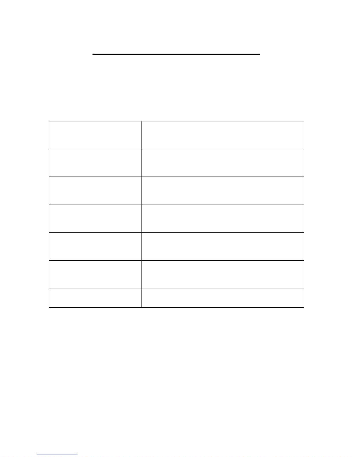
BMM HEATERS REFERENCES
Heater Models Description
BMG Horizontal Heater for ducted or AHU
applications suitable for natural gas.
BMVG Vertical heater for ducted or AHU applications
suitable for natural gas.
BMGVF Free standing nozzle head heater with force
draught gas burner.
BMGDF Free standing ducted heater with force draught
gas burner.
BMGF Horizontal ducted heater with force draught gas
burner.
BMGDD Downward discharge heater with force draught
gas burner.
2

CONTENTS PAGE
DESCRIPTION
Section 1: Introduction…………………………………………. 4
Section 2: Heater Safety………………………………………… 5
Section 3: Installers Responsibilities…………………………… 5
Section 4: Specifications………………………………………… 6
Section 5: Heater Installation & Clearances…………………... 7
Section 6: Air supply…………………………………………….. 9
Section 7: Overheat Protection Device…………………………. 10
Section 8: Flue System…………………………………………… 11
Section 9: Ventilation Requirements……………………………. 16
Section10: Gas Piping……………………………………………. 17
Section 11: Condensate Drains………………………………….. 19
Section 12: Electrical Connections……………………………… 19
Section 13: Heater Controls……………………………………... 21
Section 14: Commissioning……………………………………… 23
Section 15: Servicing…………………………………………….. 32
Section 16: Removal and Replacement of Parts……………….. 37
Section 17: Spare Parts………………………………………….. 39
Section 18: Troubleshooting…………………………………….. 40
Section 19: Users Manual………………………………………... 41
Model:
Serial Number:
3

Section 1: Introduction
The instructions refer to appliances designed to operate in the UK and
Ireland.
Appliances designed for other countries can be provided on request.
This appliance must be installed in accordance with the local and national
codes in force and used only in a sufficiently ventilated space, as specified in
these instructions.
Before installation, check that the local gas distribution systems, nature of gas
and pressure, and adjustment of the appliance are compatible.
Indirect Fired
The term ‘Indirect Fired’ indicates that the products of combustion are kept
isolated from the main supply air stream. The burner fires into a combustion
chamber, the resultant products of combustion are directed into a heat exchanger
and from there to an external flue, which discharges into the atmosphere.
Factory Test
All heaters produced by BMM Heaters Ltd will be subjected to various tests
before they are dispatched. Each heater is individual so the data will differ
between each unit. The relevant data can be found on the data plate attached to the
heater.
External Heaters
The construction of the unit will consist of double skin panels and be fully water
proof; the burner compartment will be adequately ventilated via two combustion
air grills.
Burner and Fuel
These appliances will be fitted with either a Force Induced Natural Gas Burner or
Pressure Jet Oil Burner.
Burner Type
BMM Heaters Ltd use two main manufacturers; Reillo or Weishaupt, which are
available for on/off, high/low or fully modulating appliances.
Oil Burners are available for on/off or high/low control.
4

Section 2: Heater Safety
The Installation of this appliance must be done by a registered installer/contractor
suitably qualified in the installation and service of gas fired heating equipment.
WARNING!
Improper installation, adjustment, alteration, service or maintenance can
result in death, injury or property damage. Read the installation, operation
and service manual thoroughly before installing or servicing this appliance.
Note:
To Installer: Please take the time to read and understand theses instructions prior
to any work servicing or installing this appliance.
Installers must leave a copy of this manual with the end user/owner.
To Owner: This manual must be kept in a safe place in order to provide necessary
information for service engineers at a later date.
Section 3: Installers Responsibilities
♦ To install the heater, as well as the gas and electrical supplies, in
accordance with applicable specifications and codes. BMM Heaters
recommends the installer contact a local Building Inspector, Fire Officer or
Insurance Company for guidance.
♦ To use the information given in the manual together with the local and
national codes to perform the installation.
♦ To install the heater in accordance with the Clearances to Combustibles of
this heater.
♦ To plan for the installation of supports, flues and air intakes.
♦ To provide access to burners for servicing.
♦ To provide the owner with a copy of this installation, commissioning,
operation and service manual.
♦ To never use heater as support for ladder.
♦ To ensure that there is sufficient ventilation in the area to comply with the
requirements of all relevant local and national codes.
5

Section 4: General Technical Table 1
Model
12 .37 .75 15 12 0.36 1.5 154 150 75 66
15 .37 .75 19 15 0.432 1.8 154 150 75 66
18 .37 .75 23 18 0.44 2.2 154 150 75 66
23 .47 .75 30 23 0.7 2.9 154 150 75 66
30 .75 .75 38 30 0.94 3.9 154 150 75 66
44 .82 1.55 57 44 1.08 5.4 154 150 207 192
59 1.13 1.55 75 59 1.75 7.3 154 150 207 192
88 1.55 1.55 113 88 2.62 10.9 154 150 207 192
117 2.11 2.58 150 117 3.48 14.5 204 200 246 228
Min
Air
flow
m³/sec
Max
Air
flow
m³/sec
Heat
Input
kW
Heat
Output
kW
Max Start
Gas Rate
m³/hr
Gas
Flow
Rate
m³/hr
Flue
Spigot
Nominal
Ø mm
Flue
Size
Ø mm
Weights
External
Heater
Kg
Weights
Internal
Heater
Kg
147 2.58 2.58 188 147 4.18 17.4 204 200 246 228
176 3.19 5.17 225 176 5.23 21.8 204 200 420 384
205 3.75 5.17 263 205 6.1 25.4 254 250 420 384
235 4.23 5.17 300 235 6.98 29.1 254 250 420 384
264 4.75 5.17 338 264 7.85 32.7 254 250 420 384
293 5.17 5.17 376 293 8.71 36.3 254 250 420 384
352 6.23 6.23 451 352 10.32 43 304 300 1704 1364
440 8.46 10.34 537 440 13.08 54.5 304 300 1704 1364
513 9.40 10.34 658 513 15.24 63.5 304 300 1704 1364
586 10.34 10.34 752 586 17.42 72.6 354 350 1704 1364
733 13 16.53 939 733 19.34 80.6 406 400 2304 2160
880 15.35 16.53 1127 880 26.14 108.9 406 400 2304 2160
952 16.53 16.53 1221 952 28.32 118 406 400 2304 2160
Each appliance has been range rated; burner pressures can be found on the data
plate and the burner pressure once commissioned must be entered in the actual.
6
Section 5: Heater Installation
Before installation, check that the local distribution conditions, nature of gas
pressure and adjustment of the appliance are compatible.
The air heater must be installed in accordance with the rules in force and the
relevant requirements of any fire regulations or insurance company’s requirements
appertaining to the area in which the heater is located, particularly where special
risks are involved, such as areas where petrol vehicles are housed, where cellulose
spraying is carried out, in wood working departments etc.
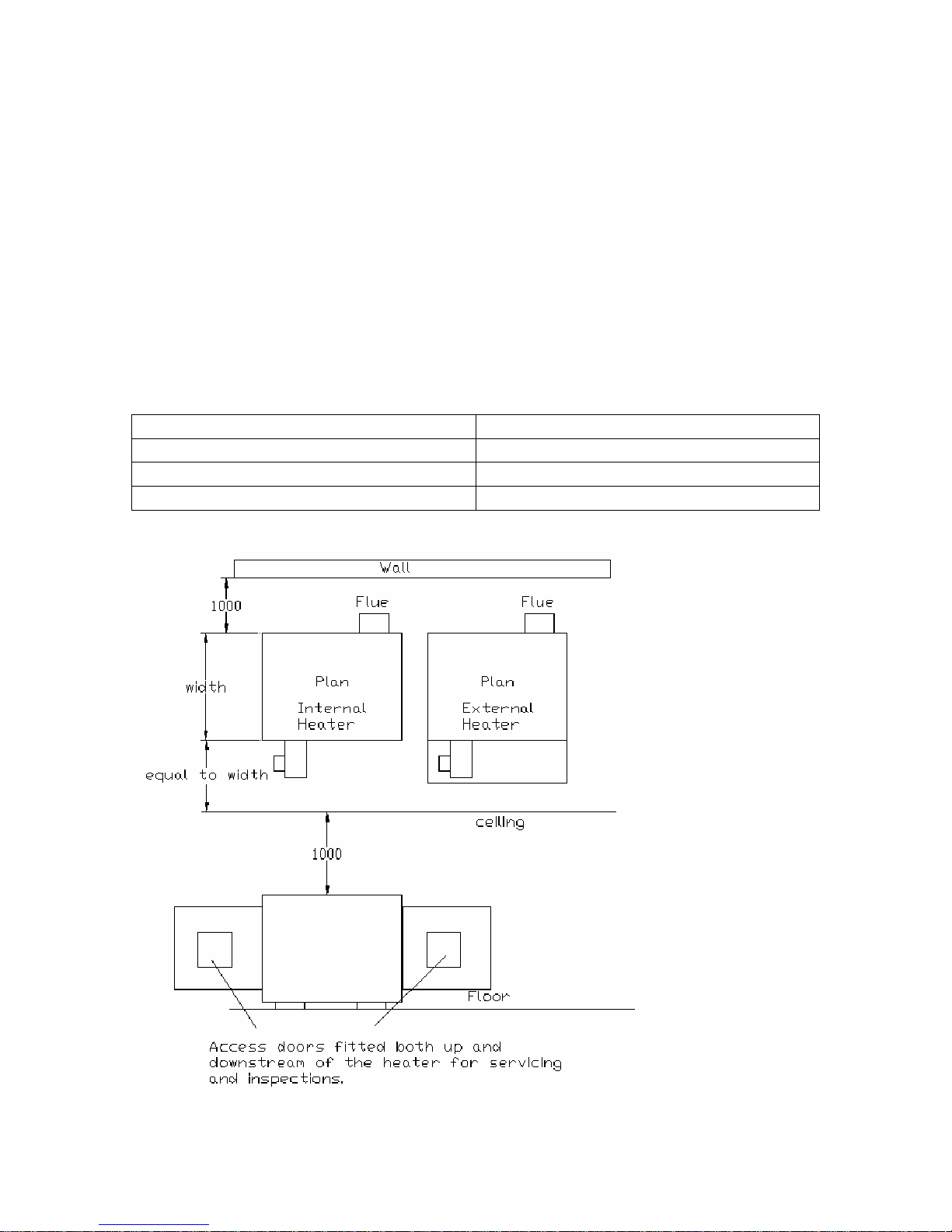
Clearances and Positioning:
The following clearances for installation and servicing must be observed.
To the front Equal to the depth of the heater.
To the rear 1.0m
To at least one side 1.0m
Above the heater 1.0m
Clearances fig.1
7

Clearances
A minimum of 500mm upstream and downstream must be allowed for, due to the
radiant heat. Filters must be fireproof, if fitted and a motor shield is required over
the main supply fan motor if directly in front of the heater.
When installing the heater, minimum clearance is required around the heater.
If the heater is to be fitted at a height, then the structure of the gantry must be
capable of the heaters weight (which can be found in section 4, table 1), also a safe
working platform and access must be allowed for; to enable easy and safe working
access.
Note: The front of the heater is the side on which the burner is fastened.
When designing a system, allowance must be made so equipment can be serviced
after installation and for the fitting of any spares, which may be required. The
BMG is designed to be installed within an Air Handling Unit or ductwork.
The appliance is designed to work in a maximum ambient temperature of 40°c.
The Air Heaters are mounted direct on the floor and do not need any fixing. The
base on which the heater is positioned should not be less than 150mm (6 inches)
thick and must be constructed of non-combustible material.
Any combustible material adjacent to the heater and the flue system must be
placed or shielded as to ensure that its temperature does not exceed 65ºC.
WARNING!
No air heater shall be installed where there is a foreseeable risk of flammable
particles, gases, vapours or corrosion inducing gases or vapours being drawn
into either the heated air stream or the air for combustion. In such cases
installation may only proceed if the air to be heated and the air for
combustion are ducted to the heater from an uncontaminated source,
preferably outside the building.
If this heater is to be suspended then weight in table 1 in section 4 must be taken
into account.
8

Section 6: Air Supply
Ductwork
All delivery and return air ducts, including air filters, jointing and any insulation
or lining must be constructed entirely of materials, which will not contribute to a
fire, are of adequate strength and dimensionally stable for the maximum internal
and external temperatures to which they are to be exposed during commissioning
and normal operation. In the selection of materials, account must be taken of the
working environment and the air temperatures which will result when the overheat
limit thermostat is being commissioned. Where inter-joint spaces are used as duct
routes, they should be suitably lined with fire-resisting material.
A full and unobstructed return air path to the air heater must be provided.
If the air heater is to be installed in a plant room, the return air and warm air
discharge arrangements must be such as to avoid interference with the operation of
the flue by the air circulation fan. The return air intake and the warm air outlet(s)
should therefore be fully ducted, in the plant room, to and from the heater,
respectively. The openings in the structure of the plant room through which the
ducting passes must be fire stopped.
In addition, where there is a risk of combustible material being placed close to the
warm air outlets, suitable barrier rails should be provided to prevent any
combustible material being within 900mm (3 ft) of the outlets.
Air flow
It is essential that the correct amount of air is provided through the heater and
should be evenly distributed when entering the heater. All pressure
calculations/resistances for air are ambient with the Heater in the ‘off’ position.
Adjustable by pass plates
BMG models fitted into larger cabinets for internal or external use should be fitted
with adjustable air balancing plates or a simple restriction damper. If the work is
not going to be carried out by BMM Heaters Ltd then we recommend that the
installer ensures that it can be altered to give guaranteed minimum equal air over
the combustion chamber/heat exchanger (see minimum and maximum air flow
volumes in section 4 table 1).
9
Section 7: Overheat Protection Device
Overheat protection is fitted in case the air flow falls below the minimum
necessary for safe operation of the heater, which may be caused by failure of the
supply fan motor or belt failure, dirty filters or inlet damper failure. If the air flow
falls too low, the high limit will trip out and will require manually resetting. If this
happens on a regular basis it must be investigated by a competent registered
engineer as this could cause serious damage to the heater.
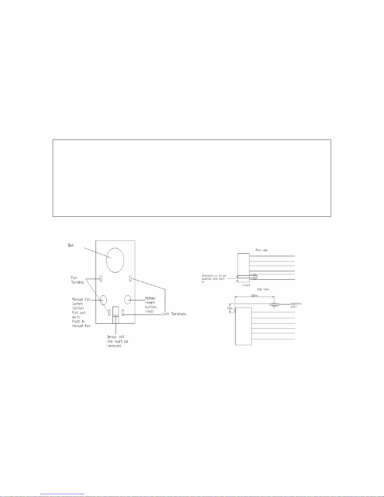
WARNING!
If the heater has a Honeywell combined thermostat installed then the jumper
link must be removed from the replacement thermostat.
Heat exchanger damage may be the result.
Failure to follow these instructions can result in death, injury, property
damage or product damage.
Honeywell overheat stat Fig 2 Overheat Position Fig 3
Ensure that the fan and limit settings are as follows:Fan On 35ºc
Fan Off 25 ºc
Limit 20 ºc above normal running temperature no greater than 100 ºc
10

Section 8: Flue System
The flue system must be made to the following specifications:
a) Mechanically robust.
b) Resistant to internal and external corrosion.
c) Non-combustible and durable under the conditions to which they are to be
subjected.
d) Stainless steel flue is recommended.
Design
When designing a flue system for the appliance the designer must take into
account the following points.
a) The flue gases exiting the appliance can be as great as 350 ºc and as low as
70 ºc on modulating burners.
b) Prevention of condensation within the flue and the management of drainage
from the flue; for example the use of twin wall flue will minimise the
condensation.
c) Flue must be a type acceptable to current standards.
d) Facilities should be made for the disconnection of the flue from the heater
to aid servicing and inspection.
e) This appliance does not require a draught diverter.
f) BMM Heaters recommend that a 90º Tee condensate piece is connected
directly onto the heater spigot, from this point the flue must then rise
vertically with no horizontal runs of flue pipe or 90º bends. If there is an
unavoidable obstruction then the use of 45º bends will be permitted.
(Please contact BMM Heaters if more that two 45º bends are used).
g) The flue should terminate in a freely exposed position and must be situated
as to prevent the products of combustion entering the building via any
opening.
h) A Flue terminal must be fitted.
i) The flue installation must be designed to the latest gas regulations and any
local environmental standards.
j) Where a flue passes through a combustible roof, ceiling or floor, the flue
pipe should be surrounded with a metal sleeve, the size of which should be
sufficient to provide a space not less than 25mm between the flue pipe and
the sleeve when positioned.
Note! Flue connection sizes can be found in section 4 table 1
11

Minimum and maximum flue heights
Internal: 600mm above the apex is the minimum height above the building if
within 1.5 metres of the surface, see drawings Figure 1 & 2.
Maximum height is no more than 25 metres, if this exceeded please
consult BMM Heaters or consideration should be given for a fan
assisted flue.
External: Minimum flue height is 1 metre above appliance roof.
Maximum height is no more than 25 metres, if this exceeded please
consult BMM Heaters or consideration should be given for a fan
assisted flue.
Flue terminal
A flue terminal (must be approved) needs to provide an extraction effect under
virtually all wind conditions, the free area of outlet openings should be at least
twice the nominal area of the flue. Outlet openings should be provided preferably
all round, or at least on opposite sides.
It is important for the terminal of an individual open flue system to be located so
that it is not likely to be subjected to wind pressures which could restrict or reverse
the flow of combustion products through the flue.
The ideal position is above the highest point on the roof. It is absolutely essential
that the terminal is positioned outside the building so that it is freely exposed to
any wind and is not shielded by any roof structure or object to such a degree that
they create undesirable pressure regions around the terminal.
12
Preferred positions are:
- At or above the ridge of a pitched roof by means of a roof terminal.
- Above the intersection with a pitched roof.
The pitch or angle of the roof will determine the required flue height from the base
of the terminal. See Table 2 below:
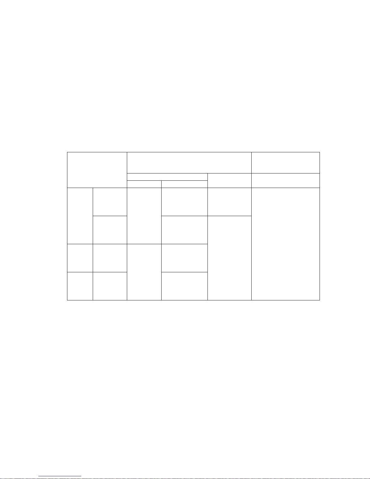
Table 2
RECOMMENDED LOCATIONS OF ROOF TERMINALS:
Location not within 1.5m of a vertical surface*
Type of roof
on the roof
Internal route
Pitch
Pitched
exceeding
45°
Flat With
Without
Pitch not
exceeding
45°
parapet
parapet
On ridge Not on ridge
At or
above roof
level (see
figure 4)
Not
applicable
1m above flue/
roof
intersection (see
figure 3)
600mm above
flue/roof
intersection (see
figure 4)
600mm above
flue roof
intersection (see
figure 6)+
250mm above
flue/roof
intersection (see
figure 10)
External route Internal route
See figure 3
The base of the
terminal to be
600mm above
the level of the
adjacent roof
edge (see
figures 1, 6
and 10)
Location within 1.5m of
a vertical surface* of a
structure on the roof
External route
The base of the terminal
to be 600mm above the
level of the top of the
structure (see figures 2,
5, 9 and 11)
*For example: a chimney stack dormer window; tank room; lift motor room;
parapet, etc.
+When the flue outlet is at a horizontal distance greater than 10 times the
height of the parapet or structure, the terminal outlet height need be only
250mm above the roof.
13
 Loading...