

Page 1
Page 2
Message from BMI Racing
The DB12R is a revolutionary step forward in 1/12th scale car design. Two years of research and
development has culminated in the kit you have before you. The goal of the DB12R project was to take the
best features of T-bar cars and Link cars and combine them to make a new type of rear suspension that will
set new standards for speed, versatility and ease of use. I call this new suspension system the BMI Flex Link.
What if you could have a t-plate car that was as stiff side to side as with a .075” t-plate but more flexible front to
rear than a .063” t-plate with 2 screws in the read pod?
What if you could have a link car that had insane steering with very little front wheel travel, transitions left to
right in chicanes like it was hard wired to your brain and was equally at home on carpet and asphalt?
Stop wondering, the DB12R delivers on all of the above.
The DB12R’s suspension allows racers to enjoy the rising side to side spring rate inherent in a T-bar rear
suspension system with the separation of the front to back versus side to side spring and damping effects as
seen in link cars. This allows serious racers to balance forward traction, side traction and steering
aggressiveness independently of each other with the ultimate goal in mind. This means FASTER LAP TIMES!
Please read through the instruction manual carefully. Even if you are an experienced R/C racer, there are
some details about the DB12R that are different. To get the most out of your kit you must have it assembled
correctly.
With Regards,
Items needed to assemble your DB12R
1. .050”, 1/16” and 3/32” Allen wrenches
2. A #2 Phillips Screwdriver
3. 3/16” and 11/32” nut drivers
4. A pair of needle nose pliers
5. A pair of slip join pliers
6. A hobby knife
7. A ruler or calipers
8. A file
9. A soldering iron
10. Diff Grease
11. Electric Motor Cleaner Spray
12. 35wt silicon shock oil (for center shock)
13. 5000wt silicon diff oil (for damper tubes)
Jason Breiner
BMI Racing
Items needed to operate your DB12R
1. Two channel surface Radio system
2. A mini servo*
3. One or more 4 cell battery packs
4. A battery charger
5. An electronic speed control
6. An electric motor
7. A 64 pitch pinion gear
8. A small servo saver.
9. 1/12thscale body
10. 1/12thscale tires
* The DB12R was designed for servos with
dimensions similar to the Futaba 9602 and 9650.
These will fit perfectly with a centered output shaft.
Other servos will fit but may require different servo
mounts and/or modifications to the lower chassis.
Page 3
Front suspension assembly
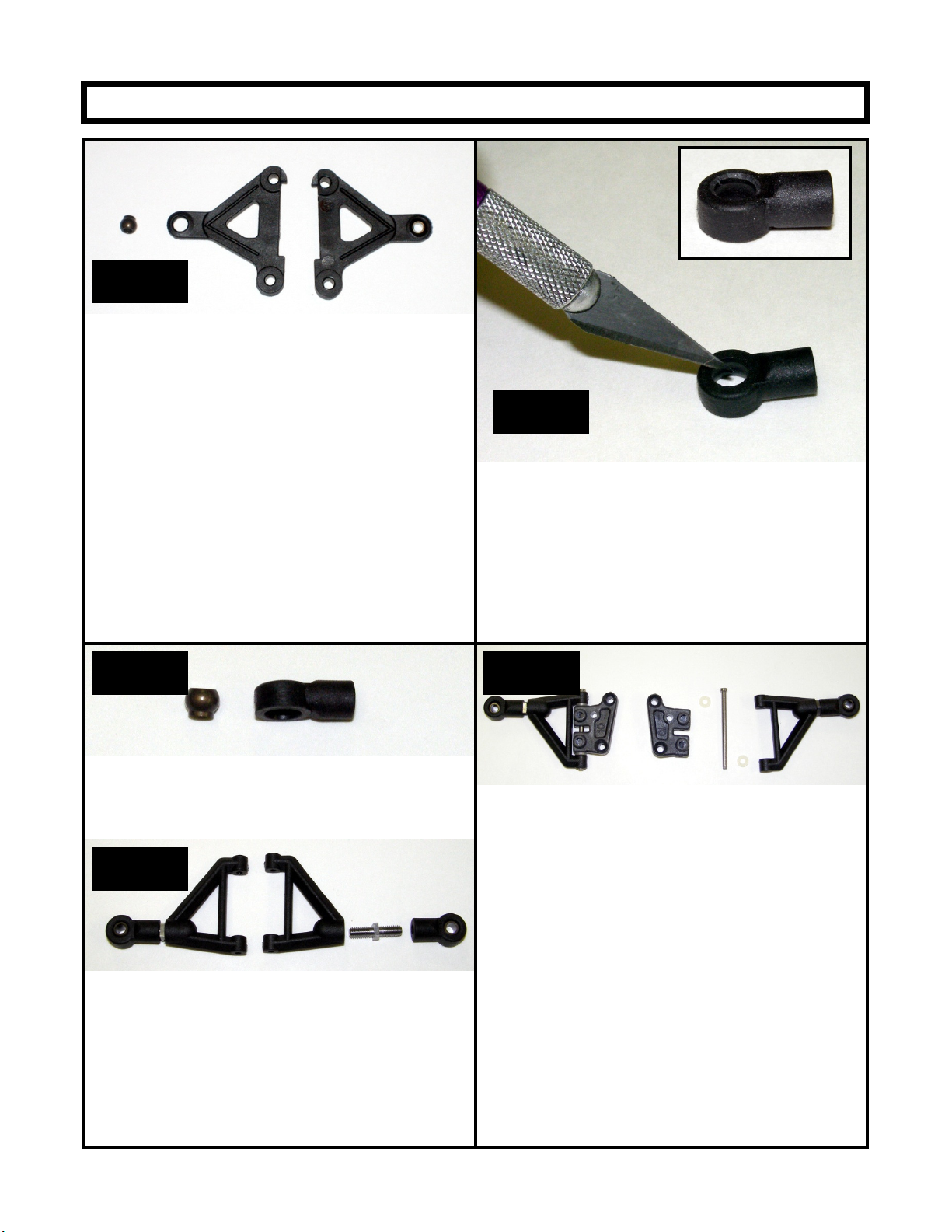
Step 1
Locate your lower front suspension arms and the
hard anodized alloy pivot balls. Note that the arms
are symmetrical. At this time you must pick which
one will become the left and right arms as this will
determine how you pop the pivot ball into the arms.
Pop the pivot balls into the arms with the shoulder
on the ball facing up. Do this by placing the ball on
a hard flat surface and placing the arm over the
ball. Carefully push the arm down over the pivot
ball. Be careful. It will take a lot of force.
Special Note:
The DB12R uses IRS hard anodized alloy pivot
balls and the new IRS lower suspension arms. If
the balls are tight in the lower arms carefully
squeeze them with pliers until the ball just begins to
move freely
Step 2
Locate your upper suspension arm rod ends. Note
that the top side of the rod end opening is smaller
than the bottom
With a hobby knife, carefully chamfer the top of
the rod ends opening. This creates clearance for
the king pin shims that will go here later. This will
ensure there is no binding in the suspension.
The inset picture shows a finished rod end.
Step 3
Locate the two remaining hard anodized alloy pivot
balls and snap them into the upper arm rod ends with
the shoulder on the ball facing down. As with the lower
arms, squeeze the rod ends if the balls do not move
freely.
Step 4
Locate the upper suspension arms, the upper arm
turnbuckles and assemble as shown above.
We prefer to thread the right hand thread portions
of the turnbuckles into the rod ends and the left
hand thread into the upper arms.
Note:
The arms have a bottom and a top. They have
small circular impressions on the bottoms.
Step 5
Locate the 10 degree reactive caster upper
suspension mounts, upper suspension hinge pin,
e-clip and nylon caster spacers.
Assemble as shown.
Make sure the upper suspension arms pivots
freely. If there is any binding at all, the car may
handle poorly. If the upper arms are tight, use the
back of a hobby knife to scrape the front and back
of the reactive caster blocks and the inside of the
upper suspension arms to make more clearance
for the caster spacers. Take your time here and
get it right!
Special Note:
The DB12R uses IRS upper hinge pins and does
not require setscrews in the upper suspension arm
mounts.
Page 4

Step 6
Attach the upper
suspension arm assembly
to the lower suspension
arms as shown with 4-40 x
½” screws.
Step 7
Locate the left and right steering spindles. Trim the
steering arms length to the line molded on the part as
shown.
Step 8
Locate the Ti front axles, four 4-40 alloy lock nuts,
and two alloy pivot balls.
Thread the Ti axles into the steering spindles.
Note that the threads on the axles that go into the
spindles are left hand. After the axles are fully
seated tighten an alloy 4-40 lock nut onto the
threaded stub coming out the back of the spindle.
Thread the alloy pivot balls into the holes on the
steering arms and secure them with alloy 4-40 lock
nuts. Remember these are alloy pivot balls so
make the nuts snug. They are strong enough to
last a few racing seasons; but if you crank them
down, you can snap them.
Step 9
Locate 2 steel 1/8” king pins,10 1/8” shims, 4 eclips and 2 .020” springs.
1. Snap an e-clip on to one end of the king pin.
2. Slide 3 shims onto the king pins against the
e-clip.
3. Pass this through the pivot ball in the upper
suspension arms rod end.
4. Place one more shim on the king pin.
5. Slide the steering spindle onto the king pin.
6. Slide the king pin through the pivot ball in the
lower suspension arm.
7. Slide the .020” spring and nylon retainer
onto the king pin and snap an e-clip on the
bottom of the king pin.
8. Repeat for the other side of the front
suspension.
Special notes:
Make sure the steering arms on the spindle
are pointing towards the rear of the car as
shown in the picture.
The axle is offset in the spindle. Make sure
the axle is closest to the lower suspension
arm. As shown in the picture to the left
It is important that the king pin slide freely in
all of the parts including the steering
spindle. When you thread the axle into the
spindle, it may swell the king pin bore and
make it tight on the spindle. You can try to
use a 1/8” drill to open it up but the best
solution is to use a 1/8” reamer.
You can order the reamer from:
www.mcmaster.com. The part number is
2995A61
Page 5

Step 10
Locate four 8-32 x 5/8” screws and 4 nylon lower suspension arm risers.
Pass a screw through the chassis and slide a nylon riser over the screw. Start threading the screw into the
lower suspension arm but do not tighten it. Pass another screw through the chassis and slide a nylon riser over
that screw. Start threading the screw into the other hole on the lower suspension arm. Tighten both screws.
Repeat on the other side.
Special Note:
In testing, we found we preferred to not use any suspension brace, strap or tube to connect the left and right
suspension assemblies. This was true on high traction carpet tracks to low bite asphalt tracks. You can add or
remove lower arm spacers to adjust ride height and to compensate for tire wear.
Rear suspension assembly
Step 11
Locate two flex plates*, 2 Nickel Teflon plated Alloy
pivot balls, 2 delrin pivot ball housings, 2 delrin
housing caps, 2 10-32 set screws* and 4 2-56
button head screws.
1.Place a pivot ball in a pivot ball housing with the
shoulder on the ball facing down.
2.Place a housing cap over the ball.
3.Place the flex plate over this assembly.
4.Pass the 2-56 screws through the pivot ball
housing from the bottom up so they thread into the
flex plate.
5.Thread 10-32 set screw into the large hole on the
flex plate above the housing cap. Just get the 10-32
started into the flex plate for now as we will adjust it
later.
The 10-32 set screw is there to adjust tension on the
pivot ball so it can move freely but have zero play.
*Black flex plates and 10-32 set screws were used
for photos. The production links are natural G10 in
color and the production screws are stainless steel.
Page 6
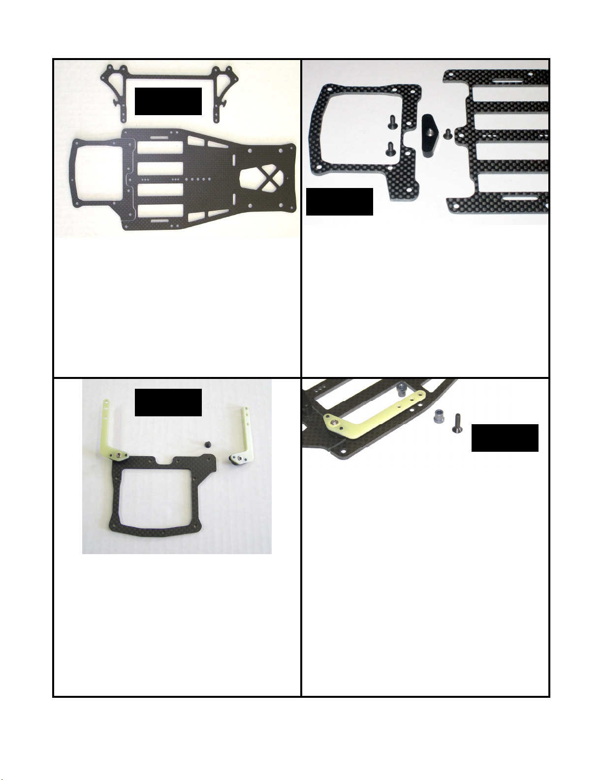
Step 12
Step 13
Take a minute to prepare all your carbon components
for assembly. With a file or sand paper knock off any
sharp edges along the perimeter or the carbon parts.
The cell slots in the chassis are designed to fit the
cells properly if you just knock off the sharp edges. If
you bevel the cell slots the batteries will hang below
the bottom of the chassis.
Special note:
Carbon fiber dust is really bad for you. Always
wear a mask and eye protection when sanding or
filing carbon fiber.
Step 14
Locate the delrin center pivot assembly one 4-40 x ¼”
and two 4-40 x 3/8” flat head screws.
Attach the center pivot assembly to the rear most hole
in the center of the lower chassis plate with the ¼”
screw. The shoulder on the pivot ball and the two
bosses on the center pivot assembly should face
down towards the chassis. The pivot ball has a 3/32”
hex in the top so you can use a wrench to tighten it
firmly.
Attach the rear lower pod plate to the center pivot
assembly with two 4-40 x 3/8” flat head screws.
Step 15
Locate 2 gray anodized non-threaded spacers, 2
gray anodized threaded spacers and 2 4-40 x ½” flat
head screws.
1.Pass a 4-40 x ½” flat head screw through the hole
in the chassis corresponding to the front hole on the
flex plate.
Attach the two flex plate assemblies to the real lower
pod plate with 4-40 x 1-4: flat head screws.
Temporarily remove the 10-32 set screws in the flex
plates in order to access the 3/32” hex in the top of
the pivot ball so you can tighten it down firmly.
Replace the 10-32 set screw and adjust it so there is
no play between the pivot ball and the pivot ball
housing on the flex plate. However, the flex plate
must still move freely. If you lift the front of the flex
plate, it should fall under its own weight when you let
it go.
2.Pass a gray non-threaded spacer over the screw.
3.Slide the forward hole on the flex plate over the
screw and the spacer.
4.Thread the gray threaded spacer onto the screw
and hold it with needle nose pliers as you tighten
the screw.
5.Repeat to assemble the other side
Note: Use forward mounting holes in flex plate and
chassis as a starting point
Page 7

Step 16
Locate the two alloy rear pod plates, the alloy rear
pod plate spacer tube 2 4-40 x 3/8” flat head screws
and 4 4-40 x ¼” flat head screws.
Attach the alloy pod plates to the lower carbon pod
plate with the 4 4-40 x ¼” screws.
Step 18
Locate and install the two long gray anodized threaded
spacers as shown with 4-40 x ¼” flat head screws
Step 18
Attach the alloy rear pod plate spacer tube to the
allow rear pods with the 2 4-40 x 3/8” screws.
Step 19
Locate the damper tube parts bag, the rear pod top
plate and 4 4-40 x ¼” flat head screws..
1.Thread a 4-40 x ½” set screw into each of the 4
ball cups from the damper parts bag.
2.Thread a ball cup/set screw assembly into the
ends of each of the damper tube pistons and
damper tubes.
Locate and install the two carbon damper
tube/body mount wings as shown with 4-40 x ¼”
button head screws.
3. Apply 5000wt silicon diff oil to the pistons and
insert them into the damper tubes.
4. Attach the alloy pivot balls to the bottom of the
pod top plate and the tops pf the side wings as
shown above. Secure them with alloy lock
nuts
5. Attach the carbon pod top plate to the alloy
rear pod plates
6. Snap the ball cups of the assembled damper
tubes onto the pivot balls on the pod top plate
and wings.
Note:
If you feel play between your ball cups and
ball studs, you can place a single layer of
plastic bag material between your ball cup and
ball stud then snap them together. This will
cut and insert a disc of plastic into your ball
cup reducing or eliminating the play. If you
still feel play, repeat the process. We find you
usually need one to two layers to get the
proper feel, no play but totally free movement.
Page 8

Step 20
1. Install the molded shock mount-antenna mount
with 2 4-40 x 3/8” flat head screws
2. Assemble the IRS Nickel-Teflon Pro Shock as per
the included instructions with 35wt silicon shock oil.
3. Place the one long black alloy ball stud in the
antenna mount and a standard ball stud in the rear
pod top plate as shown. Secure the top pod plate
ball stud with an alloy lock nut.
4. Install the included gold shock spring onto the
shock and snap the shock in place.
Trim the ball cup on the shock that attaches to the
antenna mount to .472” (12mm) in length. Thread this
short ball cup on so the over all shock length is 2.6”
(66mm). This length will give you the standard setting
of 1.5mm of rear pod droop. If you thread on the ball
cup until it stops, you will have zero pod droop.
Step 21
Locate the rear axle parts bag. There are a couple of steps
that can make your diff last longer that should be done at
this time.
Use the right alloy diff hub as a holder and sand both sides
of each diff ring on 600 grit sand paper using electric
motor cleaner spray as a lubricant. Sand until you see an
even scoring pattern across the face of each diff ring.
Clean them with motor spray and set them aside.
The diff balls may have a protective oil coating on them.
Place them on a clean paper towel and carefully clean
them with motor spray. When dry drop them into your cup
of diff grease and stir them to coat them with diff grease.
Diff Assembly:
Step 21 Continued
1. Put a small dab of diff grease on the axle flange
so the diff will stick to it. Place a diff ring on the
flange so its flat keys onto the flat on the diff
flange.
2. Place a flanged 3/8 x ¼” bearing in the center
of the spur gear. Slide the spur gear and
bearing unit on to the axle until it stops against
the diff ring.
3. With a small flat screw driver remove the diff
balls from the diff grease and snap them into
the outer row of holes in the spur gear.
4. Place a flanged 3/8 x ¼” bearing into the inside
face of the right side diff hub. Put a small dab of
diff grease on the hub flange so the diff will
stick to it. Place a diff ring on the flange so its
flat keys onto the flat on the hub flange. Slide
this unit on to axle.
5. Slide a flanged 3/8 x ¼” bearing over the axle
into the outside face of the right side diff hub.
Slide the stepped thrust cone onto the axles so
the smaller diameter part is against the right
hub bearing.
6. Thread the black nylon lock nut onto the
threaded stud on the axles until it makes
contact with the thrust cone.
7. Tighten the black lock nut gradually with an
11/32” nut driver until you notice you cannot slip
the spur gear when holding the axle and right
hub in a fixed position.
Six 4-40 x ¼” cap head screws are supplied to mount
your rear wheels.
Notes:
Keep you fingers clean with motor spray. Diff
assembly is like surgery. You do not want dirt
or oil where it does not belong.
The grease on the diff balls when you pluck them out
of the cup of diff grease is all you need.
Smearing diff grease on the rings will make
your diff get dirty faster and make a mess.
The ultimate goal in building a diff is one which is
extremely free and glass smooth but requires a
lot of force to slip the spur gear.
Page 9

Step 22
Step 23
Insert the IRS precision ride height adjuster cams into
the rear alloy pod plates. Insert a 3/8” x ¼” flanged
bearing into each ride height adjuster and insert the
axle as shown. Note that the left clamping hub has
the shallow center boss out towards the wheel. This
is necessary to have symmetrical wheel spacing.
Install your favorite wheels and measure the width of
the car. Shim as necessary to obtain a centered axle
and a 172mm rear track width.
Special Note:
The DB12R is designed to work with IRS precision
ride height adjuster cams. We find too much size
variation in other cams and cannot guarantee they will
fit properly.
Step 24
Angled Mounting
Install a 4-40 x ½” set screw into each flex plate.
Special note:
While these long set screws were initially designed
to be tweak screws in testing we found the nature
of the rear suspension system never lets the car
get tweaked.
Now, the set screws in the flex plates function as
roll stiffeners. If you want less roll in the rear of
you car, you can run them down so they just touch
the top of the lower chassis.
Under most conditions we run them so they are not
touching, or we do not install them at all.
You have two servo mounting options with the
DB12R, Angled or Flat. The new BMI Servo
Mounts have holes to allow either mounting option.
The Reactive Caster front suspension used on the
DB12R is designed to function best with angled
servo mounting. The hardware supplied with this
kit is what you need for angled mounting.
Flat Mounting
If you wish to mount your servo flat, you will need
two long off set ball studs to replace the standard
offset ball studs on your steering spindles. These
ball studs will correct the steering geometry and
eliminate the bump steer present if you did not use
them.
The servo is mounted to the servo mounts with two
4-40 x ¼” button head screws.
Page 10

Step 25
The Servo mounts are attached to the lower chassis
with two 4-40 x ¼” flat head screws.
At this time drill out the center holes on your servo
saver (not supplied) for two Nickel Teflon ball studs.
Secure them with two 3/16 alloy lock nuts.
You have two sets of servo mounting holes in the
chassis. They let you achieve proper linkage
geometry whether you run your ball studs in front of
the servo saver as shown or behind them. This is a
valuable tuning option as the servo’s weight has a big
effect on chassis weight distribution.
Step 26
Locate two titanium turnbuckles and four black ball
cups. Assemble them as shown and adjust them to
an over all length of 2.375” (60.5mm). This is a
starting point. You will need to reset their length after
setting your camber in order to achieve the desired
amount of front toe.
Note:
You can use the same plastic bag trick mentioned in
Step 19 to remove play in your steering linkage.
Remember you want to remove play but still have
totally free movement in the links. Any friction at all is
unacceptable and will make you car not center
properly after steering inputs
Step 27
Install your body posts with two 4-40 x 3/8” flat head
screws in the front and two 4-40 x ¼” button head
screws in the rear..
Step 28
Install the battery locater with 2 2-56 flat head
screws.
You can secure your batteries with the supplied
battery o-ring or strapping tape. Both methods
work well.
Congratulations, your done!
Go to the starting setup sheet, adjust your car to
the base setup and hit the track!
 Loading...