

Page 1
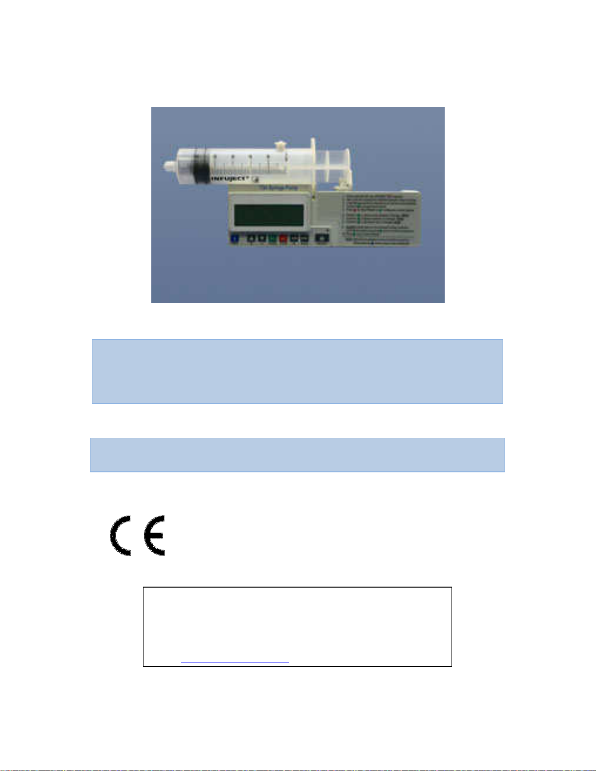
Service & Repair Manual
Infusion System
Manufacturer:
Ref: 100:090SS
E-mail:
c-m-e@internet
-
zahav.net
19/06/2007
T34 Syringe Pump
0473
BME June 2006
Tel. +1-800-323-575-00
Staufenburgstr. 23 Lichtenstein
P.o.b. 1248 Lichtenstein 72805 Germany
SERVICE MANUAL
Page 2
Service & Repair Manual
1
2
3
6
4
5 7 8 9 10
1112 13 14 15
19/06/2007
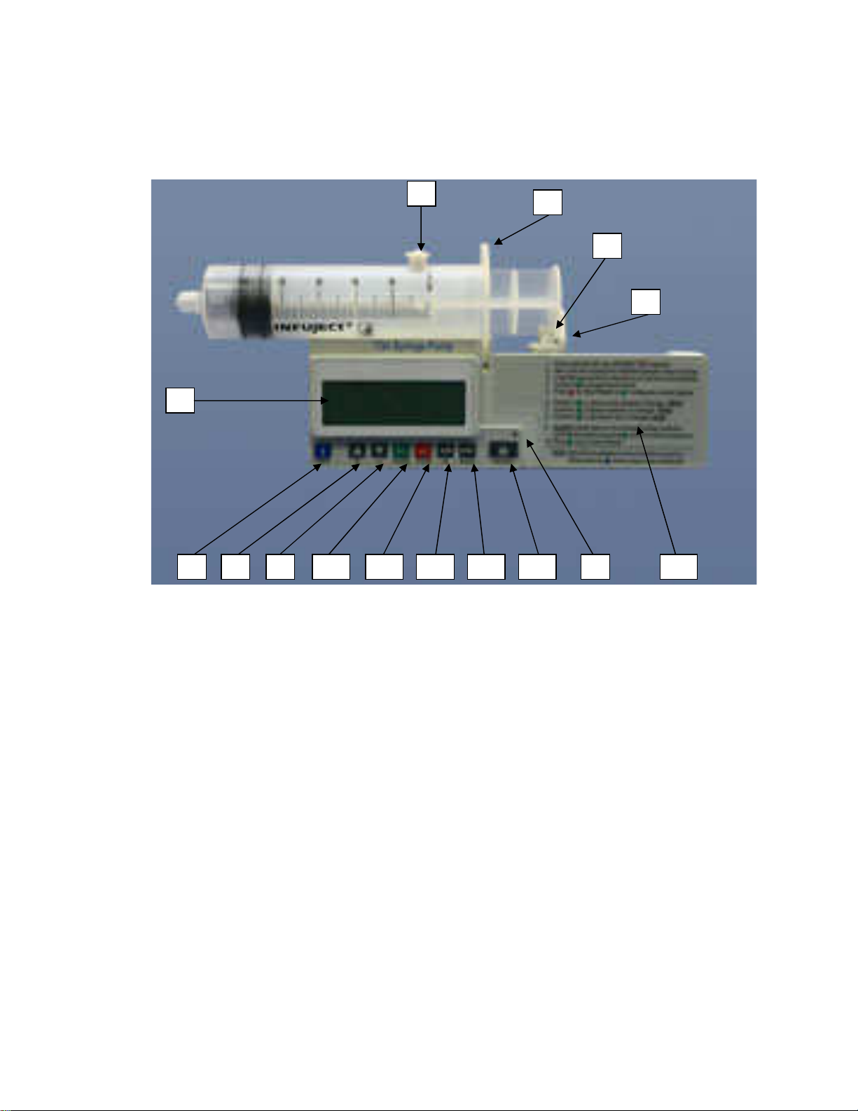
T34 Syringe pump
1. Barrel Clamp arm
(
detects Syringe size/width of barrel)
2. Syringe ear/collar sensor
3. Plunger sensor
4. 4 line LCD display
5. Operation LED
6. Actuator
7. Info Key
Long press will lock/unlock keypad)
8. Up arrow key
options)
9. Down arrow key (
10. YES/START key
11. NO/STOP key
12. FF (Forward) key
13. Back (Reverse) key
(detects correct loading of syringe plunger)
(back light (can be disabled) when any key pressed)
(green shows infusing (can be disabled), red when stopped or alarm)
(drives the syringe plunger to deliver syringe contents)
(a. shows Event Log, Volume infused, volume to be infused and battery status. b.
(a. increase infusion parameters during programming/use. b. Scrolls between
a. decrease infusion parameters. b. Scrolls between options)
(confirms choices during programming, begins infusion)
(takes user back a step during programming, stops pump)
(moves actuator forward when no syringe present)
(moves actuator backwards when no syringe present)
14. ON/OFF key
15. Instructions for infusion setup
(
detects correct loading of syringe collar)
Page 3

Service & Repair Manual
19/06/2007
TABLE OF CONTENTS
Introduction 4
Terms used in manual 4
Alarm Conditions 5
Info Mode 6
Access Code list 7
Technician Menu 9
Operational Checklist 10
Trouble Shooting 13
Maintenance Flow Chart 18
Maintenance Procedures 19
Battery Operation 24
Service Information 25
Failure Identification 25
Corrective Actions 25
Volume Test 29
Occlusion Pressure Calibration 30
Syringe Travel Calibration 32
Syringe Diameter Calibration 33
Change Setup 34
Lock Mode 36
Service and Maintenance 38
Symbols, Warnings and Cautions 39
Intended Use 40
Warnings 40
Service Centre Recommended Parts 42
T34 Syringe Pump Default Settings 43
LIMITED WARRANTY 45
Drawings 46
Bill of Materials 58
3
Page 4

Service & Repair Manual
19/06/2007
INTRODUCTION
• The T34 Syringe Pump provides the following features:
• Small, light and compact.
• Accuracy +/-5%
• 9v single Alkaline battery (Duracell MN1604)
• Ability to download current patient history and last 500 events
• Post-occlusion bolus prevention
• Free flow protection built in to set.
• 3 secure lock levels of keys and program
Infusion Rate: 0.1 to 1000ml/hr
Operated with a customised safe administration set
Can be latched in to docking station, which is mounted to IV pole
Silent operation
BEFORE ATTEMPTING TO CARRY OUT ANY PROCEDURES DETAILED
IN THIS SERVICE MANUAL YOU MUST HAVE BEEN TRAINED AND
CERTIFIED BY EITHER BME PERSONNEL OR AUTHORISED TRAINER.
YOU WILL ALSO NEED A COPY OF THE USER OPERATIONS MANUAL
AT HAND FOR REFERENCE
TERMS USED IN MANUAL
WARNING: I
circumstances that could result in injury or death to the patient or operator. Read and
understand this manual and all warnings completely before operating the T34 syringe
pump.
Caution:
that could result in damage to the devise. Read and understand this manual and all
cautions completely before operating the T34 syringe pump.
ndicates that the information is a warning. Warnings advise you of
Indicates the information is a caution. Cautions advise you of circumstances
Note:
Indicates that the information that follows is additional important information
or a tip that will help you operating the T34 syringe pump
4
Page 5

Service & Repair Manual
19/06/2007
ALARM CONDITIONS
At any time, when the pump detects a problem, an alarm is activated and the following will
occur:
• An alarm message appears on the display, stating the cause of the alarm and indicates
instructions for continual use. The operation LED will light Red.
• An audible alarm sounds.
• The infusion stops
ALARMS
• Down Occlusion
• Pump unattended
• Low battery
• End battery
• Internal malfunction
• End program
• End travel
• Syringe displaced
• Near end 15 minutes before completion
The Troubleshooting Table describes the pump’s alarm conditions and remedies.
5
Page 6

Service & Repair Manual
19/06/2007
INFO MODE
Pressing on the INFO key during operation will
Event Log, Volume infused and Volume to be infused.
The screen will be displayed for 7 seconds
VTBI 3.8 VI 1.3
d
isplay, VOLUME INFUSED
Pressing twice on the INFO key during operation will
display the battery status. The screen will display for
7 seconds. 98%
EMPTY FULL
Note: Exit from the INFO mode is automatic after 10 sec, or can be
achieved by pressing the INFO key
BATTERY LEVEL
6
Page 7

Service & Repair Manual
19/06/2007
ACCESS CODE LIST
The T34 syringe pump has 2 access codes & a Key lock feature to control user access to
authorised personnel only and prevent tampering. Service Technicians will need to be familiar
with these codes to access all area of the pump to effect service and repair.
Code ‘99’ – Access to pump “Change Set-up” allows locking program parameters.
Code ‘123’ – Allows authorised technicians to access testing and service menu.
Key lock – Enables user to lock all but the INFO and STOP keys to prevent tempering with
the pump
BEFORE PERFORMING ANY MAINTENANCE PROCEDURE:-
a. You must have training and certification from either the manufacturer
or distributor and have recommended equipment and authorised spare
parts at hand to perform the required maintenance or repair.
b. Check the history events to define the frequency and nature of the
complaint, and record program and calibration settings at time of the
event.
c. Enter the Technician menu (power on the pump while holding the INFO
& POWER key simultaneously until the Technician Code prompt
appears). Enter code 123. Press YES key to confirm
d. Scroll to perform ‘Main Self Test’ and record any failures or issues
identified during the test.
7
Page 8

Service & Repair Manual
1. User Error
Refer issu
es back to
department head
and
2. Fault with Syringe or Administration Set
Check correct syringe is used. Is it on the
3. Failure of pump
Perform Main Self
Test on Tech Menu
4. Mechanical failure
Change the defective part
5. Electronic malfunction
Change the relevant PCB
6. Failure of sensors: Syringe detection,
Replace the module
19/06/2007
SERVICE DECISION PATHWAY
When a T34 syringe pump is returned for service or repair after a ‘fault’ is reported by a user
always request a full explanation and description of the fault experience by the user and, if
possible and appropriate, ask for the return of the administrator set in use at the time of the
fault. Be mindful of the following factors as part of service/repair procedure:-
1. Has the user operated the pump correctly? Cross reference their report with the
Operations manual to ensure the steps they took prior to the alarm did not cause
or result in the alarm state or error cause.
2. Was the fault in one of the pump sensors (identify which one and replace it) or one
of the circuit boards (identify which PCB failed and replace the board). Use on the
Technician mode, either, Main Self test to pass all the testable options or Manual
Test to select a specific function.
Possible Issues:-
sensors 1-3.
Corrective Action:-
suggest training/alerting all users to
prevent the same error being reported
approved list of syringes?
8
Page 9

Service & Repair Manual
Menu
Setting
Screen
1 Exit from Technician
Exit Technician mode
2 Serial Number
Displays
serial number and production date
3 Main
Self-test Runs through keypad, display, alarm sound,
4 Manual Test
Same as Main Self
-
test but with a menu to focus
5 Syring
e setup
Adjust default diameter on the list of approved
6 Pressure calibration
Allows calibration and pressure settings
7 Factory Press. test
Fine tuning of pressure calibrations
8 Pressure test
Tests actual pressure
9 Syringe travel
Calibrati
on of syringe travel movement
10 Diameter calibration
Tests the syringe barrel sensor
11 Syringe dead space
The actuators limitations to deliver all volume
12 Volume test
Performing flow rate test
13 Factory setting
CAUTION
–
press
ing START/YES will restore
14 Operation hours
Hours from last service
15 Service interval
Number of Hrs before Send for Service message
16 Purge Volume
Set maximum volume user can purg
e
17 Maximum Rate
Set rate limit
19/06/2007
TECHNICIAN MENU
To access the Technician Menu, press and hold the INFO key and the POWER key at the same
time until Technician code prompt appears. The display will show the software version for 2
seconds before the access code prompt. Enter code 123 to access the technical menu.
The pump will display all the parameters that can be set, calibrated and tested. The technician
can scroll through all parameters using the ARROW keys.
Item
syringe sensor test, syringe diameter test,
syringe travel test, battery test, voltage test and
exit
the user on individual tests.
syringes
(about
68mm)
factory defaults and delete all pre-set protocols
and set-up changes
9
Page 10

Service & Repair Manual
19/06/2007
OPERATIONAL CHECKLIST
INTRODUCTION
The operational checklist detailed in this section determines if the device is operating correctly
and should be carried out before and after any service or repair work. If the device fails in any
test in the checklist, the fault must be recorded and corrected prior to placing the device back
in to clinical use. Please become familiar with the checklist procedures prior to carrying out
any test.
The following test equipment is required to perform the tests in the Operational Checklist:-
o Syringe 50/60 ml filled with tap water
o Pressure gauge
o Electronic balance, burette or Infusion tester.
o Leakage current testing device (for safety test)
o Connecting flat cable between front and rear housing
Once a problem has been identified and isolated to a single assembly, the assembly should be
replaced in accordance with the disassembly procedure provided in this manual.
After all repairs are completed, the Operation checklist should be repeated and the device
should be re-calibrated.
PUMP SET UP FOR TESTING
Please ensure you have, & are familiar with, the device Operation Manual before performing
these tests. The procedure in this section are designed to check that the syringe pump is
infusing correctly prior to testing the effectiveness of the alarms. If the pump fails to
perform as described or displays an error cause – troubleshoot and repair before repeating
the test. The pump will display Restart Pump message, press the info key for more details
1. Switch the pump on; allow preloading procedure to be completed. Verify that the syringe
holder is set down.
2. Verify that all sensors (syringe holder, barrel ear and plunger ear) are blinking.
3. Load a syringe, verify that the pump detects the syringe size and brand; the pump may
detect a different brand but never a different size. (see Operation Manual)
4. Select the correct brand and press YES to confirm
5. The pump will display the calculated volume. Verify this detection is correct, if not return
to step 1
6. Confirm or change data of time default, calculated rate, and accumulated screen, start
infusion
7. Verify the operation LED changes from red to flashing green.
10
Page 11

Service & Repair Manual
A
larms
Operation Events
Timer communication fail
Event No
External EEPROM fail
Date & time
Timer battery fail
Switch on
Internal EEPROM fail
Info: Volume infused
Hardware rest
Volume to be infused
Setting test fail
Rate
Start
-
up motor stop fai
l
Type of syringe
Watch dog current
Length in ml/mm
Watch dog timer error
Pressure setting: 0
-
10psi
CPU test error
Pressure actual
Shadow compare error
Battery voltage
ADC converter fail
Rate titration
Oscillator fail
Stop
STAC overflow
Low battery
UPD counter overflow
Pump unattended
External light fail
Down occlusion
Revolution encoder fail
End travel
No motor steps
- 20min
Syringe displaced
19/06/2007
INFUSION TEST
The following test checks that the pump does not exhibit alarms or error causes during normal
operation:-
1. Switch the pump on using the ON/OFF key. Allow pre-loading procedure to be completed
2. Load a syringe (refer to Operation Manual for a list of approved syringes)
3. Verify that the pump will detect the syringe correctly. To confirm syringe type press the
YES key or use arrow key to select another brand
4. Verify the displayed volume, confirm with the YES key.
5. Change the calculated rate to 5ml/h and press YES, verify the warning screen will appear.
6. Press YES to confirm the calculated/set rate.
7. Check accumulated data on the screen and confirm.
8. Press the YES key to begin infusion.
9. If the pump stops infusing and reports an alarm, troubleshoot using the table on page 37.
10. Below is a list of events and alarms that can appear in the event log
11
Page 12

Service & Repair Manual
Motor voltage overflow
Long revolution time
Short revolution time
Over rev. in m
inute
Less rev. in minute
No rotation detected
Actual rate test err.
Start up motor move fail
Ends sensor fail
Current sensor fail
Syringe type diameter
Wrong volume length
Long stop mode int.
Reset by COP counter
19/06/2007
11. To restart infusion, press he START/YES key.
12. When the pump has delivered the selected volume, an audible alarm will be activated
while the display will show ‘Program End’ and default to ‘KVO’ if enabled. To stop the
alarm press the STOP/NO key
13. Check the pump is infusing the KVO rate
12
Page 13
Service & Repair Manual
Alarms or
Possible Cause
Action
Volume accuracy is
Wrong detection of syringe or
1. Check that the correct syringe was
Pressure accuracy is
If during maintenance the
Recalibrate pressure accuracy as
Pump does not
Batte
ry depleted
Change battery
ON/OFF key
malfunction
Replace the main PCB
1. External interrupt or
1. Restart the pump
Pump will not
The syringe holder is located
Set syringe holder to down position
The FF
and BACK
1. A syringe is loaded
1. Remove syringe
Purge d
isabled
The pump was switched on
Remove syringe, switch off and back on
Volume
cannot
be
The pump will not allow to
Software protection
Syringe holder
Syringe detection sensor
Replace syringe holder
Operation LED
Operation LED is not
Check setup, if enabled. Change main
19/06/2007
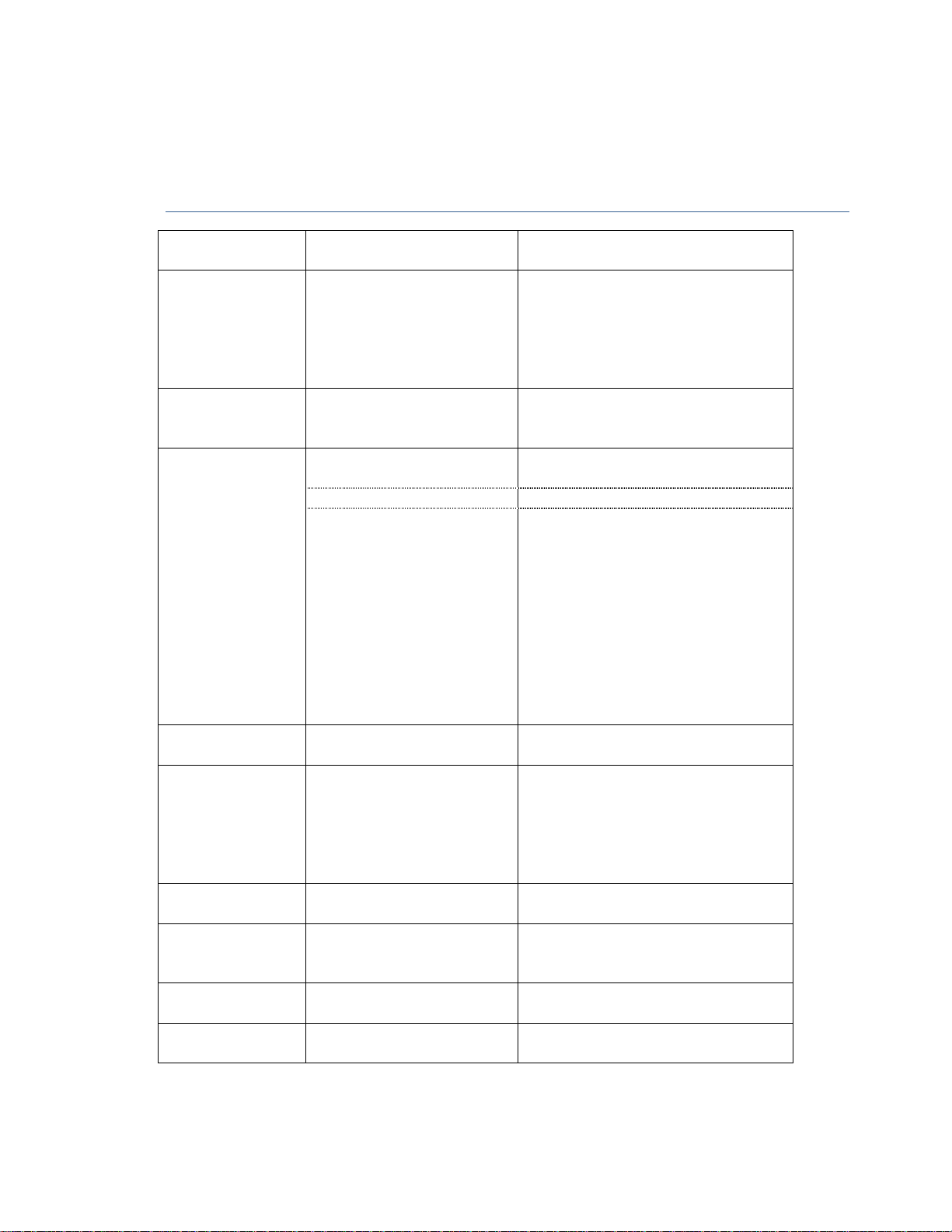
TROUBLESHOOTING
Complaints
not accurate
not accurate
switch on
incorrect setting of hard
height
pressure readings are faulty
electronic malfunction
(electrostatic discharge)
2. Encoder plate not
mounted properly
3. Encoder LEDs or
Phototransistors are
damaged
4. In the case motor can’t
turn
5. If the problem persists
selected.
2. Perform syringe travel calibration
(tech menu)
3. Check Hard height measurement in
tech menu
described in pressure calibration
section
2. Remount the encoder plate
3. Replace the encoder PCB
4. Replace motor
5. Replace main PCB
perform preloading
keys will not
function
in the upper position
2. Syringe holder is up
3. Syringe sensor
malfunction
while a syringe was loaded
increased
increase volume above the
volume of the syringe
sensor is not sliding
malfunction
malfunction
functioning during operation
2. Place syringe holder down
3. Replace syringe sensor
4. Check connection on the front
pumping block. If it has no fault
replace slide pot.
again
PCB
13
Page 14

Service & Repair Manual
Alarms or
Possible Cause
Action
Maximal basal rate
The maximal rate was west to
Change the maximal rate to higher
Rate titration
1. In the Change Setup the
1. Enable titration mode
Down occ
lusion
Occlusion detection
Recalibrate pressure accuracy as
Hardware reset or
1. External noise.
1. Turn the pump off and on again. if
Setting test fail
1. RAM corruption
1. Turn pump off and on again with
Long Stopmode int
Timer communication fail
1. Restart the pump, if problem
Startup mot or stop
1. Failure during switch on
1. Re
start the pump, if problem
Actual rate test
1. Mechanical malfunction
Check syringe, pump is calibrated to
Complaints
19/06/2007
limited
disabled
Reset by external
pin
a lower value
rate titration is disabled
2. Program is in Lock state
malfunction
2. 9V battery low or
depleted
3. Battery contact dirty
4. Mechanical malfunction
5. Motor PCB malfunction.
6. Main PCB malfunction
2. Syringe data out of range
3. Data settings corrupted
4. Device not calibrated
after main PCB
replacement
5. Corruption of serial no.
production date and dead
space
limit in ‘Change Setup’
2. Unlock program
described in Pressure Calibration
section.
Replace main PCB
problem continues send to
manufacture
2. Replace battery
3. Clean battery contacts
4. Check motor and replace
5. Replace motor PCB
6. Replace main PCB
same syringe, if problem continues
send to manufacturer
2. Enter technician menu and check
the data for the current syringe
3. Restore data with Factory Reset
4. Perform calibration of: syringe
travel, syringe diameter and
pressure calibration with 50ml
syringe
5. Enter those parameters and
confirm
or reset by COP
counter
fail
error or Long Rev.
time or Over rev, in
minutes or Less rev
in minutes
test
2. Motor PCB malfunction
3. Main PCB malfunction
or high friction of syringe
2. End of travel, forcing
against housing
3. See revolution counter
fail
14
continues send to manufacturer
2. Check lithium battery or replace
motor PCB
3. Replace main PCB
continues send to manufacturer
2. Replace motor PCB
3. Replace main PCB
operate new syringes or replace pump
assembly
Page 15

Service & Repair Manual
Alarms or
Possible Cause
Action
Watch dog current
1. External noise during
1. Restart the pump, if problem
Watch dog timer
Main PCB malfunction
Replace main PCB
Shadow compare
1. Corruption
of RAM
1. Restart the pump, if problem
Oscillator fail
1. External noise due to
1. Turn the pump off and on
again
. If
Stack overflow
Microprocessor malfunction
Replace
main PCB
UPD counter
1. Mechanical malfunction
1. Perform
syringe travel calibration
ADC converter fail
External interrupt or
Turn the pump off and on again. If
Electronic malfunction
Replace main PCB
Exter
nal light fail
1. Encoder detects external
1. Make sure pump case is closed
Complaints
19/06/2007
error
error
overflow or
Motor current
overflow
switch on
2. Motor PCB malfunction
3. Main PCB malfunction
2. Main PCB malfunction
electrostatic discharge
2. Water ingress
3. The connector between
PCB pins dirty
4. Lithium battery less 3V
5. Motor PCB malfunction
6. Main PCB malfunction
2. Motor PCB or connection
to main PCB
3. Encoder PCB malfunction
4. Encoder plate loose
continues send to manufacturer
2. Replace motor PCB
3. Replace main PCB
continues send to manufacturer
2. Replace main PCB
problem continues send to
manufacture
2. Dry the device and inspect for
damage.
3. Clean the pins of connectors
between main and motor PCBs
4. Check and replace battery
5. Replace motor PCB
6. Replace main PCB
2. Replace pumping block
3. Replace motor PCB and clean
connectors
4. Replace encoder PCB or Fasten
encoder plate
electronic malfunction
(electrostatic discharge)
light
2. External noise
3. Malfunction of encoder
PCB
4. Connecting cable
between encoder and
main PCB damaged
5. Main PCB malfunction
15
problem continues replace main PCB
correctly with 6 screws and not
damaged.
2. Turn the pump off and on again. If
fault continues return to
manufacturer
3. Replace encoder PCB
4. Check or replace
5. Replace main PCB
Page 16

Service & Repair Manual
Alarms or
Possible Cause
Action
Revolution encoder
1. External noise
1. Turn the pump off and on again. If
No motor step for
Main PCB malfunction
Replace main PCB
Internal EEPROM
Microprocessor malfunction
Replace main PCB
Memory malfunction
Turn the pump off and on again. If
No rotation
Encoder malfunction
1. Turn the pump off and on again
Start up motor
1. Lock at end travel
1. Move manually out of locking
Ends sensor fail
1. Limit sensor malfunction
1. Check or replace READ switches
Current sensor fail
1. Motor PCB malfunction
1. Replace motor PCB
Syringe type
Syringe diameter not
Enter Manual Test and perform syringe
Complaints
19/06/2007
fail
20 minutes
fail
2. Magnet on motor
adaptor weak or broken
3. READ switch 1, 2 broken
4. Encoder plate loose
problem continues send to
manufacture
2. Replace magnet on motor adaptor
3. Replace motor PCB
4. Tighten encoder plate
problem continues:-
1. Perform factory settings from
technician menu, if problem
continues...
2. Perform reset calibration and
calibrate pump again. If problem
continues...
3. Burn software again (refer to
instructions Do not save previous
calibration). Calibrate the pump
again. If problem continues...
4. Replace the main PCB
detected
move fail
diameter
Motor malfunction
2. Mechanical or motor
malfunction
3. Motor PCB malfunction
4. Main PCB malfunction
5. Encoder plate loose
6. Encoder or connecting
malfunction
2. Magnet or actuator weak
3. Flat cable malfunction
2. Main PCB malfunction
calibrated
2. Replace block assembly
3. Replace main PCB
4. If problem continues sent to
manufacture
2. Turn the pump off and on again. If
problem continues replace pump
mechanics
3. Replace motor PCB and check pins
of connector to main PCB
4. Replace main PCB
5. Tighten encoder plates
6. Check and replace encoder PCB and
flat to main PCB.
2. Replace encoder magnet
3. Check or replace flat cable
2. Replace main PCB
diameter test, recalibrate if required
16
Page 17

Service & Repair Manual
Alarms or
Possible Cause
Action
Wrong vol. lengths
Wrong data entered mm/ml
Recalibrate syrin
ge
CPU test error
Microprocessor malfunction
Replace main PCB
Timer
1. External noise during
1. Turn the pump off and on again
Timer battery fail
1. It is the first pump
1. Turn the pump off and on again
External EEPROM
1. External noise during
1. Turn the pump off and on again and
Complaints
19/06/2007
communication fail
2. Timer battery low
3. Motor PCB malfunction
4. Main PCB malfunction
2. 3v battery low/damaged
fail
2. Motor PCB malfunction
3. Main PCB malfunction
Note: In order to prevent the possibility of wrong syringe detection,
we recommend using only approved brands. Avoid using brands that their
external diameter is close, less than 0.5mm. The medical institution will
have to decide on one of them.
communication
operation after service.
communication
and set pump to operate on
0.1ml/hr. If problem continues
send to manufacturer
2. Check lithium battery. If less than
3V replace
3. Replace motor PCB
4. Replace main PCB
2. Replace 3V battery
set pump to operate on 0.1ml/hr. If
problem continues send to
manufacturer
2. Replace motor PCB
3. Replace main PCB
17
Page 18
Service & Repair Manual
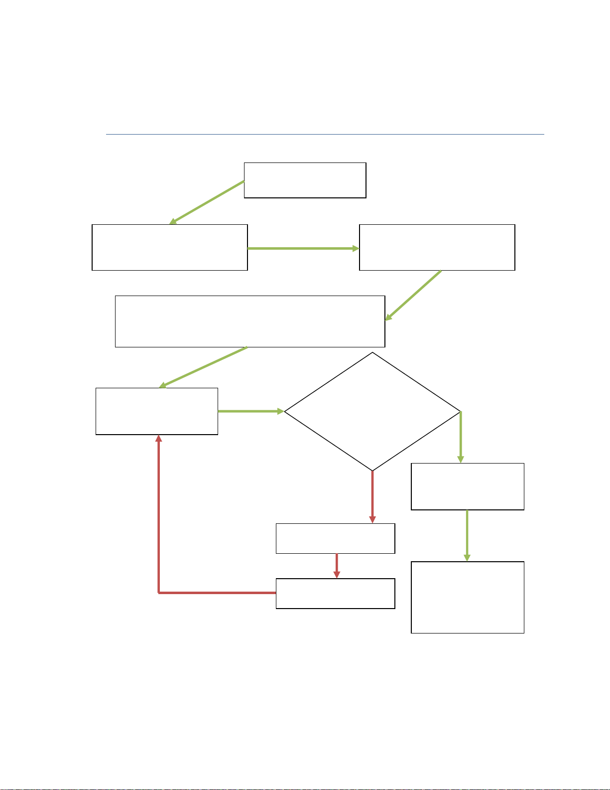
Pump returned for
Log receipt, pump serial numb
er
Power on the pump, note serial
Check history events and
note type & frequency of
Perform all tests in the
Does device pass
Checklist?
Troubleshoot
Recalibrate if any
Record that the pump
19/06/2007
MAINTENANCE FLOW CHART
service or repair
& physical appearance (i.e.
damage, signs of tampering)
alarms/alerts. Check the IV set and the liquid type that was
infused (make not of the set used and serial number)
Operational Check List
(found on page 11)
number and software version &
access Technician menu
all test and
Operation
repairs or disassembly
NO
has been undertaken
YES
18
Repair
has passed service.
Clean and return to
user group
Page 19

Service & Repair Manual
19/06/2007
MAINTENANCE PROCEDURES
MAINTENANCE INTRODUCTION
This section contains a table describing preventative maintenance which should be performed
on the T34 Syringe Pump. The maintenance procedures outlined in this section may be
performed in the hospital, by qualified and certified biomedical engineers. If an abnormal
condition occurs, which is not correctable by the following procedures, remove the device
from service and trouble shoot in accordance with the trouble shooting table, or return to
manufacturer or distributor for service
PREVENTIVE MAINTENANCE
The following table presents a list of problems, tests and collection to aid the diagnostics of
the possible pump malfunction. Review this list whenever a condition exist that does not
appear to be normal. Perform the specified checks and corrections. If the problem cannot be
corrected, remove the pump from service user service and troubleshoot in accordance to the
troubleshooting table, or return for service to the manufacturer.
Schedule: at least once a month or as required
Clean pump housing with a suitable cleaning agent as described on next page.
Check housing for damage and replace any labels that are damaged.
Schedule: at least every 12 month or as required
Perform all above tests and perform the following Functional Test Procedures
FUNCTIONAL TEST PROCEDURES
Remove Program lock.
To perform the following tests, the program lock should be disabled. To do so:-
1. Switch the pump on allow pre-Loading to complete.
2. Press the blue INFO (i) key, then scroll down (using UP/DOWN arrow keys) to ‘Change
Setup’ enter code ‘99’ by using the arrow keys. Then press YES to confirm code.
3. Scroll up the menu to ‘Program Lock’ press YES to confirm selection.
4. Use either arrow key to change the Program Lock status from ON (default) to OFF. Press
YES to confirm change.
5. Scroll down to ‘Exit’. Press YES to exit setup menu.
Note: By removing the program lock this enables you to change the
default duration so that the infusion rate available for this test is anything
up to 5ml/hr maximum set under the Technical Menu.
19
Page 20

Service & Repair Manual
19/06/2007
SYRINGE RECOGNITION AND VOLUME DETECTABLE TEST.
Equipment needed:-
• T34 syringe pump
• Selection of syringes used in the hospital or Trust.
Method
1. Switch the pump on and allow Pre-loading to complete. Position of the carriage should
not be important except possibly for some smaller syringes where the actuator may
have moved beyond the fully extended size of the syringe. Use the FF keys to move
the activator to time desired positions. FF key movement is limited for safety reasons
so repeated presses may be necessary to position.
For each of the syringe: -
2. Lift the barrel clamp arm and place the syringe on the pump as described in the
Operations manual ensuring the collar/flange and plunger are position correctly. Place
the barrel clamp arm down on top of the syringe barrel.
3. The LCD screen should show the LOAD SYRINGE message and after a few seconds a
volume and brand. If this screen remains with parts of-the syringe graphic flashing (or
a message is shown) check the loading of the corresponding syringe part or follow the
message to complete correct placement of the syringe.
4. The pump should ALWAYS display the correct volume but may not always immediately
give the correct brand. Use the arrow keys to scroll through the list of syringe brands
(pump shows those within +/'-3% diameter of the one loaded). Select the correct
syringe brand and press YES to confirm selection.
5. Read the actual volume on the syringe and compare it with what the pump reads the
volume as, these results should be within +/-3%. If the result does not fall within the
expected range
a. Check that there is no slack in the system (visible space in the seating of the
plunger or the collar/flange. In such cases purge may, be required before
repeating the test (refer to Operations Manual)
b. Recheck that the syringe loaded is the same brand as confirmed at step 4
i. I f the error remains outside of specification after checking point a & b
then the pump has failed the test and corrective action is required.
6. Remove the syringe, turn the pump off, place arm down and repeat steps 1-5.
20
Page 21

Service & Repair Manual
19/06/2007
VOLUME DELIVERY TEST
Equipment needed:-
• 10ml syringe filled with tap water for injection
• Syringe pump infusion set
• Pipette or Flow analyser.
1. Prepare the syringe and infusion set by attaching set to the syringe and manually
priming the infusion set to eliminate ALL air from the system
2. Attach infusion set to analyser or pipette ( using a three way valve to allow the pipette
level to be adjusted to scale )
3. Switch the pump on with barrel clamp arm down and allow Pre-loading to complete.
4. Position the carriage to fit the syringe using the FF or BACK keys.
5. Lift the barrel clamp arm and load the syringe. Use the arrow/scroll keys to select the
correct make from the list (as described in the Operations manual). Press YES to
confirm selection
6. Purse the system to ensure all the slack is taken up. With the voluble displayed press
the FF key and follow the instructions on screen. (Default purge volume is 0.2ml)
7. Change volume to be infused to 1m by using the arrow keys. Press YES to confirm
8. To speed up the test scroll down to reduce the duration of the infusion to the in
minimum allowed (scrolling will cease when the minimum is reached – if 1ml volume
is selected this should be 00:12 (twelve minutes))
9. Pump will display rate but will not allow change. All changes to rate must be done by
Pressing NO to back up to Duration screen and changing the duration. Confirm Rate
5ml/hr. Press YES three further times to start infusing
10. The Near End Alarm will sound at about 1 minute before the end depending on
syringe size.
11. The T34 will alarm End Of Program or End Travel when it has delivered the 1ml
12. Check volume delivered against the volume in pipette.
21
Page 22

Service & Repair Manual
19/06/2007
OCCLUSION TEST
Equipment needed:-
• 10ml syringe filled with tap water
• Pressure gauge
1. Switch the pump on and allow pre-loading to complete. Re-position the actuator if
necessary using the FF/BACK keys
2. Load the syringe and select the correct brand from the list (as described in the
Operations Manual). Press YES to confirm.
3. Purse the system to ensure all the slack is taken up. With the voluble displayed press
the FF key and follow the instructions on screen. (Default purge volume is 0.2ml)
4. The volume is not relevant for this test so press YES to confirm the volume detected.
5. To reduce the time required for this test, use the arrow keys to scroll and reduce the
duration to the minimum allowable (probably 02:00 two hours) if the 10ml syringe is
full (5ml/hr).
6. Confirm rate displayed by pressing YES.
7. Connect the syringe to the giving set and pressure gauge assembly
8. Press YES a further 3 times to start infusion.
9. You need to watch the pump because, as soon as the T34 alarms the anti-bolus system
comes into operation causing the pump to reverse and the pressure is almost
immediately reduced to a safe level to prevent post-occlusion boluses to the patient.
Default pressure is set to 540 mmHg.
10. Check Occlusion alarm operates at 540mmHg (tolerance range 413 to 724mmHg)
22
Page 23

Service & Repair Manual
19/06/2007
ALARMS TEST
T34 has the following alarms:-
Syringe displaced – To test while the T34 is pumping take the syringe off the pump, the alarm
is activated and a screen message describes the cause.
Occlusion/Syringe Empty - Pump has sensed a pressure above the alarms level. Possible
occlusion or actuator has reached end of travel/syringe empty. Tested during Occlusion Test.
Near End - Alarms when pump is 5mm or 2 minutes from end of infusion. Whichever is
greatest? Tested during Volume test
End Program - Volume to be infused set during programming has been infused. Tested during
Volume Test.
Pump Paused to Long - Leave the pump on a setting screen and do not press any key for 2
minutes. The pump should alarm after two minutes.
Low Battery – Alarms when the Battery voltage drops to 6V
End Battery – Alarms when the battery drops to 5.8V
RESTORE PROGRAM LOCK.
Once all the tests have been performed, the Program Lock needs to be turned back on if this is
how your facility, department, hospital or trust has opted to have the device configured
To do so –
1. Switch the pump on allow Pre-loading to complete.
2. Press the lnfo (!) key and scroll down to ' Chance Setup' enter code 99 by using the
arrow keys. Then press YES to confirm code.
3. Scroll up the menu to ‘Program Lock’ use the arrow keys to change the setting from
OFF to ON and press YES to confirm.
4. Scroll down to ‘Exit’ Press YES. The LCD will return to the flashing syringe
5. Turn the pump off.
23
Page 24

Service & Repair Manual
19/06/2007
BATTERY OPERATION
The T34 Syringe Pump operates on battery power only
There are two battery alarm conditions
1. The pump will warn that the battery
is low (6V) before the ‘End Battery’
alarm activates
2. When the battery is depleted (5.8V),
the pump will cease operation and
the “End Battery’ alarm will be
activated
• If the battery runs out, End Battery appears on the display. The pump stops the
infusion.
• From the End Battery sate the user can not restart the pump, until the battery has
been replaced with a new one
ELECTRICAL SAFETY
The T34 complies with the following
standards:EN 60601-1 (Medical Electrical Equipment
Safety)
EN 601-2-24 (Infusion pumps and controllers)
IEC 60601-1-4 (Programmable Electrical Medical Systems)
UL 2601-1 and CAN/CSA C22.2 No 601.1
Note: User should verify that the battery is in good condition, by
pressing the INFO key during program set up or operation. Pressing twice
the INFO key to display the battery status.
LOW BATTERY
END BATTERY
24
Page 25

Service & Repair Manual
19/06/2007
SERVICE INFORMATION
While under warranty, the instrument must not be opened by unauthorised personnel.
The customer will pay all shipping costs (returned for service or under warranty). The unit
must be packed in its original packaging. Or in another that will provide adequate protection
during shipment
To ensure prompt return, the customers’ service department must be notified before
shipment of any unit for repair. When calling the manufacturer or distributor service centre,
please be prepared to provide the serial number of the device.
A brief written description of the problem should be attached to the instrument when it is
returned for service.
FAILURE IDENTIFICATION
Specific errors, which may occur in operation of T34 Syringe pump, and the remedy for each
problem, are presented on the Troubleshooting Table.
On the info mode, user may display the pump’s history, to identify the pump failure. User can
scroll through the last 512 events. Press on the arrow up key to show the next event. The
events are displayed from the last to the first. Press the INFO key to full disclosure of all data
relevant to the current displayed event
The displayed failure information can be used to determine the nature of the failures and
troubleshoot its cause.
CORRECTIVE ACTIONS
DISASSEMBLY AND CALIBRATION
This section of the manual includes a list of tools and test equipment required for
maintenance, removing and placing subassemblies.
To ensure the device is operational, perform the operational checkout completing any of the
procedures in this section.
TOOLS AND TEST EQUIPMENT
The following tools and test equipment is required to perform the procedures contained in
this section. Since all fasteners on this device are metric, ensure that all tools used are for
metric fasteners. Tightening torque on certain screws are specified in kg - cm and in lb for your
convenience. The values in ‘lb’ are approximate.
25
Page 26

Service & Repair Manual
Equipment:-
• Digital voltmeter
• Pressure gauge
• Digital balance or liquid measurement burette
• Stop watch
• Electronic Balance
• Anti - static mat.
• Anti - static work surface.
• Piston cover mounting device
• Pump front and rear extension cable
• Small craft knife
• Pliers
• Small Diameter Test Bar (12.7mm)
• Large Diameter Test Bar (29.4mm)
19/06/2007
Tools:-
• Phillips screwdriver. M3
• Normal screwdriver. M3
• Allen key 0.9 mm.
• Forceps
26
Page 27

Service & Repair Manual
19/06/2007
DISASSEMBLY / ASSEMBLY - PUMP
Disassembly of the 134 Syringe pump is limited to mechanical components. It is recommended that
electrical problems be corrected by replacing entire pc board, either main PCB or motor, unless
circumstances warrant component repair. Use only the replacement parts list.
Please read all steps in the procedure before beginning. The procedures are given in order of
disassembly. Disassembly the device only as far as required to complete the repair. All fastening
components such as screws, washers and nuts used in the device are metric, be sure using metric
tools and replace only with metric components. Ensure all gasket material is put back in place during
reassembly.
SEPARATION OF FRONT AND REAR HOUSING
Turn the device off and place it face down on an anti- static mat or a soft work surface. Make sure
there are no metal parts like screws and nuts on the working surface, in order to avoid scratches to
the pump housing.
Remove the battery from the battery compartment, on the rear.
Remove the 6 mounting screws. Five located on the rear housing of the pump one beneath the
battery cover. These 6 screws connect the front and rear housing. All 6 screws are M2.
Stand the device and separate the front and rear housing.
Reassemble the housing in the reverse order.
Make sure the front and rear-housing surface are lined up before tightening.
Press the syringe collar sensor in to enable connection of rear and rear housing.
Replace the 6 mounting screws and tighten them to 5 kg / mr with a torque screwdriver.
After reassembling switch the pump ON and check that the Self-test and pre-loading procedures are
performed correctly.
REPLACEMENT OF MOTOR AND PUMPING OPERATIONS
1. Separate the front from the rear housing of the pump.
2. Remove the upper label (where the syringe sits), remove the 2 fixing screws.
3. Remove the instruction label and remove 1 fixing screw.
4. Disconnect the motor connector on the main PCB.
5. Pull the block assembly out.
6. Reassemble in reverse order.
7. After removing the motor and pump operations the following calibrations will need to be
performed:
a. Syringe Travel
b. Syringe Diameter
c. Pressure calibration
8. Refer to the "Calibration Procedure" chapter in this manual.
9. Perform the operation checkout.
27
Page 28

Service & Repair Manual
19/06/2007
REPLACEMENT OF PC BOARDS - MOTOR AND MAIN
1. Separate front and rear housing of the pump.
2. Remove block assembly.
3. Remove the PCBs. Note the released spacers.
4. Install a new motor or a new main PCB in reverse order.
5. Perform the operation checkout.
6. When replacing the main PCB. Because some of the calibrations are specific to every pump.
The following calibrations will need to be performed:
a. Syringe Travel
b. Syringe Diameter
c. Pressure calibration
7. Refer to the "Calibration Procedure" chapter in this manual.
8. Perform the operation checkout.
REPLACEMENT OF PUMP MOTOR ASSEMBLY
1. Separate front and rear housing of the pump.
2. Remove the block assembly.
3. Remove 2xM2 screws using the 0.9 Allen key from front block.
4. Separate front block with motor from screw assembly and bosses.
5. Remove the 2xM2 screws from block. Rotate motor and adaptor to slit on from block assy.
6. Replace using thread locking glue.
7. Install a new motor and replace in reverse order.
8. After removing the motor and pump operations the following calibrations will need to be
performed:
a. Syringe Travel
b. Syringe Diameter
c. Pressure calibration
9. Refer to the 'Calibration Procedure' chapter in this manual.
Perform the operation checkout.
REPLACEMENT OF REAR PCB
1. Separate front and rear housing of the pump.
2. Unsolder copper contact (Syringe collar sensor) and battery box wall contacts from PCB.
3. Remove drive contact 10 with spring 7.
4. Remove copper contact 12.
5. Open 3 M2 screws 16.
6. Lift PCB.
7. Install a new Rear PCB and replace in reverse order.
8. Perform the operation checkout.
28
Page 29
Service & Repair Manual
Volume Test
Monoject 20 ml
Select
, press YES
Monoject 20
ml
Select
, press YES
Monoject 20 ml
Select
, press YES
Monoject 20 ml
0
10
19/06/2007
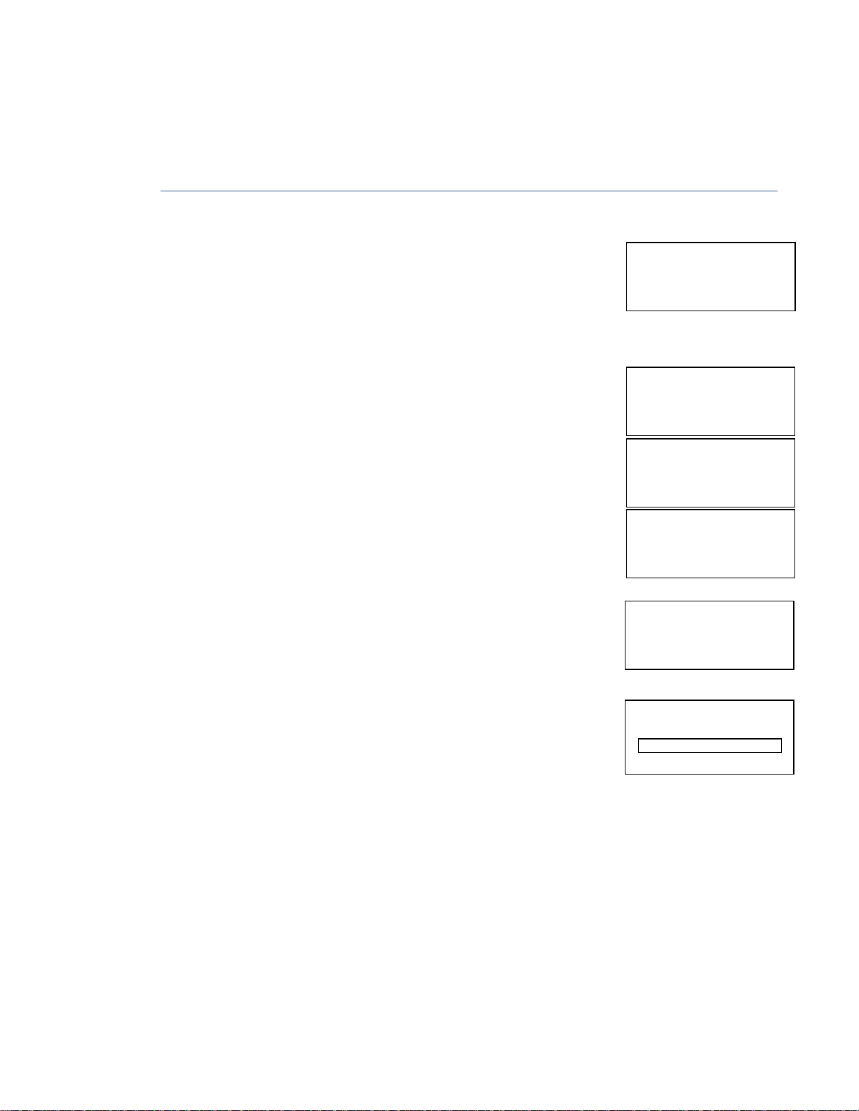
VOLUME TEST
1. Enter Technician Mode by holding Info key and Power key down simultaneously until the
software version is displayed and after 5 seconds the access code prompt will appear.
2. Using the arrows set code 123 and confirm by pressing START/YES key.
3. Use the arrow keys to scroll to "Volume lest" option and choose this option, using the START/YES
key.
4. The display will instruct to "Load Syringe" do so. the display will change
to show the syringe loaded
Technician Code
123
Load Syringe.
5. Press YES to confirm, or change to the correct Syringe Brand
Pressing the YES key will enable the user to set the required rate for the
volume test, set the rate and confirm with the YES key.
6.
Set the required volume for the volume test, select a volume that
is lower or equal to the syringe volume.
7. During the volume test the pump will display the volume to be infused in
a graph that will empty according to the volume infused.
8. The volume test is recommended after every service.
Rate 12ml/hr
Volume 10.5ml
Rate 12ml/hr
29
Page 30

Service & Repair Manual
Load Force Device
Press YES to confirm
Zero Level
Connect & Press
OK
Change
, press YES
19/06/2007
OCCLUSION PRESSURE CALIBRATION
1. Press continuously the Info key while switching the pump on. Wait until the screen will show the
Technician Code - set code 123 and press the VPS key to enter.
2. Use the arrow keys to scroll to pressure calibration option. Once this option is displayed press
YES to enter.
3. The display will read
Pressure Calibration
4. Load the 4Nm calibrated syringe force gauge into the pump.
Set Plunger 1Nm
Use FF and Back Keys
5. The actuator will move to set the Zero pressure point, the display will read TRAVEL FORCE and a
number between 4 and 12. Press YES to continue.
6. Repeat the above steps, but with the 49Nm force gauge. The display will read Pressure Sensitive
and a number between 70 and 100. Press YES to continue.
To fine tune the pressure calibration use the Factory Press. Test.
FACTORY PRESS. TEST
7. Scroll down to Factory Press. Test press YES.
8. Load a 5ml syringe (loaded with water) select the correct brand press YES.
0 mmHg
9. When the pumps display shows the above message connect the syringe to a pressure gauge and
press the YES key. The pump will continue to drive the syringe and the pressure can be seen to
rise on the gauge and on the pump display. When the pump thinks it has reach 540mmHg it will
alarm and the display will read
540mmHg
Zero Level Sensitive
11(10) 86
30
Page 31

Service & Repair Manual
Change
, press YES
19/06/2007
10. If the reading between the pump and the gauge is different then you need to adjust the Zero
Level. Press the Yes key twice.
Repeat the above test.
Once the two readings are within spec, remove the 5ml Syringe.
Repeat steps 7 to 9 but with a 50ml syringe (loaded with water)
540mmHg
Zero Level Sensitive
11(10) 86
11. To adjust the upper limit (Sensitive) from the above screen press the YES key once and using the
arrow keys change the Sensitive up or down. Repeat until the readings are with spec.
12. To confirm that the pressure calibration is successful use the Pressure Test routine.
PRESSURE TEST
1. Scroll down the Tech menu until PRESSURE TEST is displayed press YES.
2. Load any test syringe (filled with water) connect the syringe to a pressure gauge and press YES.
3. Select the correct Brand of syringe. Press YES
4. The pump will drive the syringe and the pressure can be seen to rise on the pump display and
the pressure gauge. The pump will Bleep when the test has finished.
5. Check the pump display against the pressure gauge to ensure the results are within spec.
Note: The zero level data shall remain in the pump memory until changed by
the User.
BME is recommending the user to repeat this procedure once a year
PRESSURE SETTING
In the Change Set Up option the user can select a pressure level between 100 -15OOmmHg.
31
Page 32
Service & Repair Manual
Press YES
- continue
19/06/2007
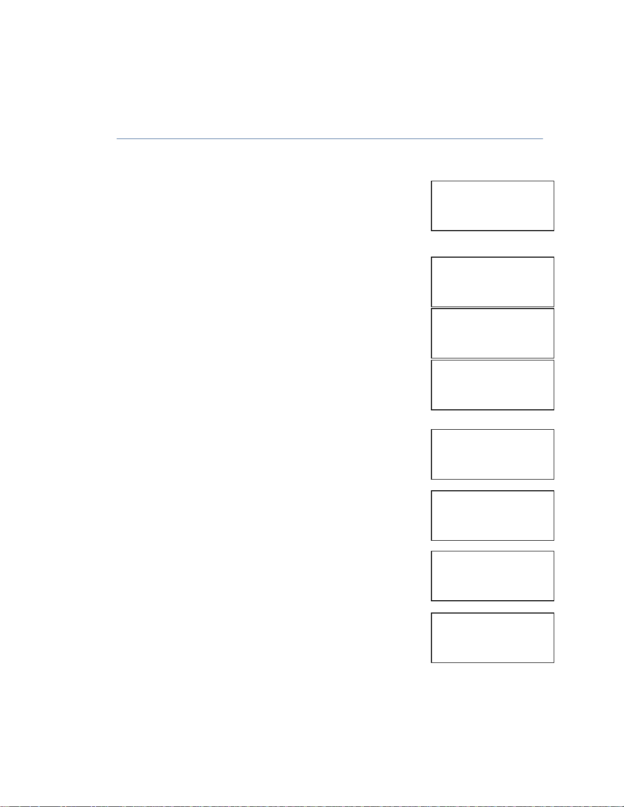
SYRINGE TRAVEL CALIBRATION
1. Enter Technician Mode by Hold Info key and Power key down simultaneously until the software
version is displayed and after 5 seconds, the access code prompt will appear
2. Using the arrow keys set code 123 and confirm by pressing
Technician Code
123
3. Use the arrow keys to scroll to "Syringe Travel" option, press the START/YES key.
4. The display will instruct to "Remove Syringe", if loaded, do so, the
display will change to show Press FF key
Press FF key
Confirm min. Travel
5. Press YES to confirm. The actuator will move forwards indicating
'Locating min travel', when it reaches the end the display will change
to say
"Confirm min. Travel’
check that the actuator is touching
and Press YES key. Press BACK key, the display will say Locating max.
travel, wait until the actuator arrives.
6. The display will change to say Confirm max travel, again check that
the actuator is touching and press YES key. The display will show.
Press BACK key
Press FF key
7. Press the FF Key and once again the actuator will move to the
front. Once the actuator arrives, the display will ask technician to
confirm min. travel with YES key.
8. Press YES to confirm
9. The Travel is specific to every pump and serves as confirmation
screen that the travel calibration was completed successfully.
10. Press YES to exit procedure.
32
Locating min. Travel
Confirm min. Travel
Press YES - continue
Travel 65.6mm
Press YES - continue
Page 33
Service & Repair Manual
Press YES
- continue
Press YES
- continue
Change
, press YES
Syringe Diameter Test
Press YES
- continue
19/06/2007
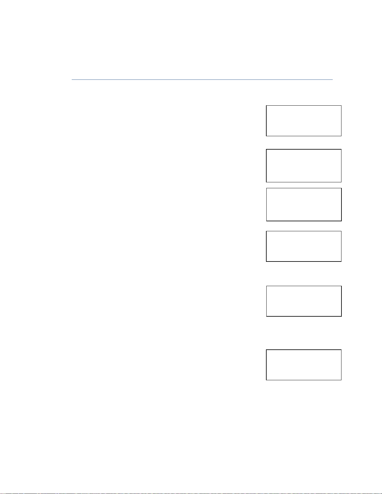
SYRINGE TRAVEL CALIBRATION
1. Enter Technician Mode by Hold Info key and Power key down simultaneously until the software
version is displayed and after 5 seconds, the access code prompt will appear
2. Using the arrow keys set code 123 and confirm by pressing
3. Use the arrow keys to scroll to "Diameter Calibration" option, press the START/YES key.
Technician Code
123
4. The display will instruct user to set the barrel clamp to down
position, do so and confirm with YES key.
5. Set the barrel clamp to the upper position and press YES key
6. The display will change to say Load any syringe from 2 to 5 ml and
press YES key. Load the small diameter test bar or a known
diameter syringe into the pump and hold it with the barrel clamp.
The pump will show the actual diameter, change the diameter to
the correct size or confirm with the YES key
7. The display will change to say Load any syringe from 35 to 50 ml
and press YES key. Load the large diameter test bar or a known
diameter syringe into the pump and hold it with the barrel clamp.
The pump will show the actual diameter, change the diameter to
the correct size or confirm with the YES key
Locate Barrel Clamp
to down position
0
Locate Barrel Clamp
to upper position
255
Load 2-5ml syringe
Diameter_12.3 mm
Load 35-50ml syringe
Diameter_32 mm
Change , press YES
8. Technician will calibrate only one syringe: the pump will adjust the
dimension automatically for all the others.
9. Press YES to exit procedure.
33
32.4 mm
Page 34
Service & Repair Manual
Change Setup mode access with code 99
F F K e y O pe ra ti o n
B a c kl ig ht Du ra ti on
L i m it s ba c kl ig ht d ur a ti o n to h el p pr e se rv e ba t te r y li fe
In f o D ur at io n
L i m it s th e l en gt h of ti me t he I nf o s cr ee n i s di s pl ay ed
O p e r at io n L ED
T u r ns o f f th e gr eb e f la sh in g op er at i on L ED t o pr e se rv e b at te r y li fe
T i t ra ti on Op t io n
E n a bl es s
et t in g a t it ra t io n li m it w it hi n ma x. r at e r an ge
O c c lu s io n Pr es s
ur e s e t ti ng at w hi c h oc cl us i on a la rm w il l ac t iv at e
KV O O p er at i on
A c t iv at e s Ke e p Ve in O pe n i nf us io n at E nd of I nf us io n
Info Menu
:
Change
, press YES
Info Me
nu:
19/06/2007
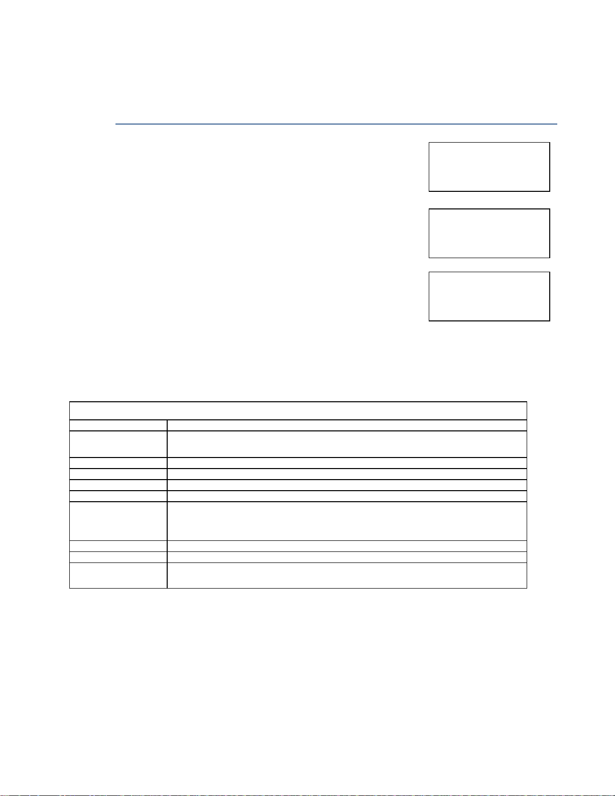
CHANGE SET-UP
Switch the pump on in normal mode. Press the INFO key twice.
1. Choose "Change Set-up" to display all software adjustable
parameters.
Battery Level
Change , Press YES
2. Set Change set-up Code (Code 99). Using the arrow keys and
confirm with START/YES key.
3. Confirm with START/YES key.
A list of settable parameters on the "Change Set up" menu is on
the next page.
4. Scroll through the setting parameters, using the ARROW keys and change if necessary.
T i m e & D at e E n s ur es al l ev en t s in l og ar e co r re ct ly d at e a nd ti me s ta mp e d.
Li m it s t he f or wa r d mo ve me nt of a ct ua t or c au s ed b y pr e ss in g t he F F ke y du r in g
s y r in g e lo ad in g
D e f au lt D ur a ti on
W h e n a ne w p ro gr a m is c on fi rm ed Pu mp r es et s t o th is de f au lt ( se tt in g t o ze r o
s k i ps du ra ti o n st ep du ri ng p ro gr a mm in g) . Wh en Pr og ra m Lo ck ON ( se e be l ow )
c a n no t b e se t t o ze r o.
Enter Setup Code
99
EXIT
Select , Press YES
P r o gr am L o ck
P r e ve nt s a lt er a ti on o f e it he r du ra t io n or ra te du ri ng s e t up ( wi th P r og ra m Lo ck
ON De fa ul t D ur at io n c an no t b e se t t o ze ro )
34
Page 35
Service & Repair Manual
Syringe Size
Syringe Brand
20ml Plastipak
19/06/2007
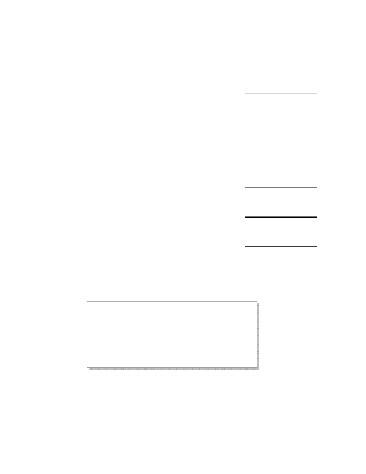
TO RE-ENABLE A SYRINGE TYPE TO THE PUMP MENU
1. Enter Technician Mode by Hold Info key and Power key down simultaneously until the software
version is displayed and after 5 seconds, the access code prompt will appear
2. Using the arrow keys set code 123 and confirm by pressing
Technician Code
123
3. Use the arrow keys to scroll to "Syringe Set-up” option, press the START/Y'ES key.
4. The display will show the sizes of syringe, scroll up or down to the
correct syringe size needed. Confirm with YES key.
2ml
Select , Press YES
5. The pump will display the list of store brands, select the correct
one and confirm with YES key.
If the syringe has been disabled the display will show this, to re -
20ml BD Plastipak
Select Press YES
enable this syringe press NO and Yes to confirm.
The display will then show a summary of the manufactures data for
that syringe. Press YES to confirm
Syringe Disabled
Refer to Ops Manual
REMOVE A SYRINGE FROM THE PUMP MENU.
To remove a syringe from the pump menu repeat steps 1,2,3,4 and 5 the display will show the summary
of the manufactures data for that syringe press NO, the display will be 'Delete this syringe?' press Yes
key to delete or No to go back. A deleted syringe can be reinstalled by following the above instructions.
Syringe sizes available for the Australasian Market:
Braun Omnifix 2 5 10 20 30 50
BD Plastipak 3 5 10 20 30 50
BD Precise 20
Codan/Once 2.5 5 10 20 50
Monoject 6 12 20 35 50
Terumo 5 10 20 30 50
35
Page 36
Service & Repair Manual
19/06/2007
LOCK MODE
The 134 Syringe pump provides three different level of locking:
Level 1 Keypad Locking
During operation all keys are disabled excluding the STOP/NO and the INFO key. During
programming all keys are disabled excluding the START/VF.S and the INFO key.
Level 2 Program Locking
This feature enables the operator to lock out the setting keys, so that entered parameters, or
set programs cannot be changed once they are set. This option is important, for example, with
children as users, when there is a danger that the child might play with the pump and
unknowingly change the program: or for home-care patients who repeats the same program
every day. Locking the program prevents mistakes in setting
Level 3 Maximal Rate Locking
This feature enables the operator to set a maximal rate for the pump to accept. The program
rate then can be adjusted only up to a preset limit.
HOW TO LOCK
Level 1 - Keypad locking
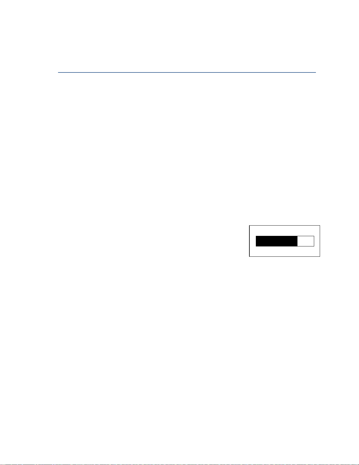
Press and hold the INFO until the entire graph is black and a beep is heard.
The beep indicates that the locking program is turned ON.
• The number one is displayed in the upper-right corner of the
screen.
• The keys are locked in memory until they are unlocked or until
entering Change set up mode.
To unlock the keys:
Press and hold INFO key until the entire graph is cleared and a beep is heard. The beep indicates that
the locking program is OFF. The number one is no longer displayed in the upper-right corner of the
screen and the keys are unlocked.
Level 2 - Program locking
1. Press INFO key twice from STOP or setting mode.
2. Scroll to "Change Set up" option.
3. Enter code 99. and press
4. Press YES key to enter change Set up Mode
Using the arrow keys scroll to "Lock Mode".
The default setting is OFF
Unlock in the same procedure
36
Page 37

Service & Repair Manual 19/06/2007
KVO Rate
Adjust and Press YES
Level 3 - Maximum Rate Locking
The home-care company can adjust the Maximal rate acceptable according to patient needs:
1. Press continuously the info key. While switching the pump on set technician code 123 and press
YES key to enter.
Use the arrow keys to scroll to Maximum Rate option. Once this option is displayed press YES to
enter
2. Set Technician Code (Code 123). Using the arrows keys, and confirm
with YES.
3. Scroll through the setting parameters, using the ARROW keys, until
the "Maximal Rate" option. Confirm with YES key.
4. Set the maximal rate, using the ARROW keys and confirm with
YES key.
Technician Code
123
Select , Press YES
Bolus Rate
Maximal Rate
Maximal Rate
500ml/h
Note: The selected Locking Option will remain in the pump’s memory until
changed.
Whenever the pump is in more than one locking level the higher level will be
displayed on the right si9de of the screen
37
Page 38

Service & Repair Manual
Before connecting the pump to a p
lightly dampened with warm water and a mild detergent or disinfectant.
turn the pump off
docking station from AC power before cleaning.
: Do not clean the pump or docking station with chemicals suc
solvents. These chemicals can cause damage to plastic components and paint. Use a lint
d with warm water and a mild detergent or disinfectant.
: Do not soak or immerse any part of the pump or docking
If the pump is to be stored for an extended period it should be cleaned and the battery removed. Store
clean, dry atmosphere at room temperature and. if available, employ the original packaging for
Perform functional tests once every three months.
the unit using a lint
h as Xylene
station in water.
SERVICE & MAINTENANCE
CLEANING
19/06/2007
Warning: Always
Warning: Always unplug the
Caution
free cloth dampene
Caution
STORAGE
atient, and periodical during use, Clean
and remove the battery before cleaning.
-free cloth
, Acetone or similar
-
in a
protection.
Page 39
Service & Repair Manual
SYMBOLS, WARNINGS AND CAUTIONS
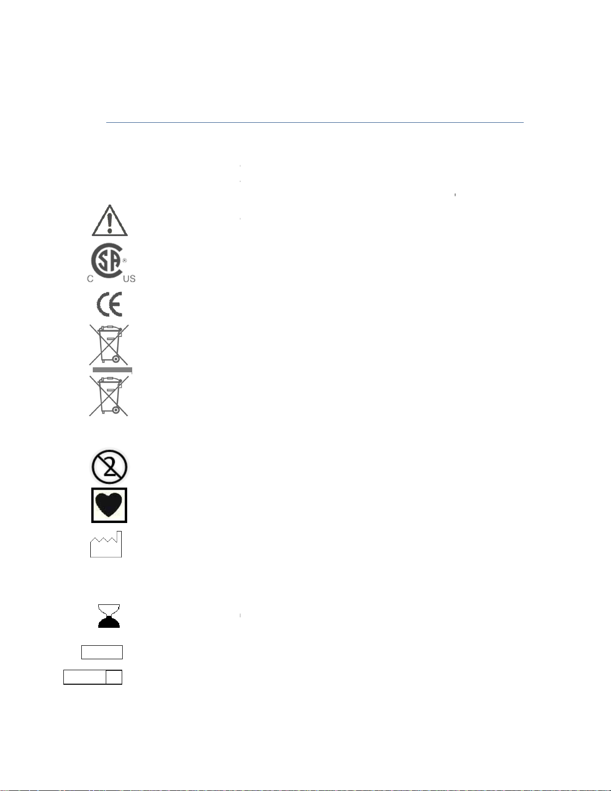
The following symbols are used on the T34 Syringe
the system or statements in this manual proceeded by any of the following words and or symbols are
of special significance, intended to help you to operate the pump in a safe and successful manner.
, consult accompanying Instructions.
CE mark indicates conformance to Medical Device Directive 93/42/TTX,
Do not dispose of in municipal waste. Symbol indicates separate collection for
-
Do not dispose of battery in municipal waste. Symbol indicates separate collection for
Level of protection against fluid ingress
use disposable c
hazard. Do not reuse single
Expiry Date of disposable
ene Oxide
39
pump Infusion System and components. Labels on
ective 2002/96/EEC). NOTE: Does not apply to the battery.
omponents on more than one patient is a biological
SYSTEM SYMBOLS
19/06/2007
IPX1
Attention
CSA Mark
electronic equipment
battery is required.
The use of single-
(WEEE Dir
-use disposable components.
electrical and
Type CT applied part.
Date of Manufacture
SN
LOT Lot Number
STERILE EO Sterilized with Ethyl
Serial Number
Page 40
Service & Repair Manual
The T34 syringe pump is designed to transfer medication and fluids intravenously. The system is
intended for patients who require maintenance medications and general l.V. fluids
To avoid possible personal injury or loss of life, observe the following:
Read the entire Operation Manual before using the pump, since the text includes important
maximum volume that may be infused under S1NGFF FAULT CONDITI
Voltage present on internal components may cause severe shock or death upon contact.
personnel should open the pump cover.
Blown fuses could cause a fire hazard. Replace blown fuses on
type and rating (see fuse values on the Docking station PCB).
The equipment is not suitable for use in the presen
mixture. Do not use the T34 in the presence of these gases.
impair the operation of the
Before operation, verify that the IV line is not kinked or occluded.
Any adjustments, maintenance, or repair of the uncovered p
n System and/or the accuracy of the infusion. Authorized skilled technicians should
perform any adjustments, maintenance, or repair of the uncovered pump. Any adjustments,
maintenance, or repair of the uncovered pump while connected to the power should be
34 Syringe pump should be operated within a temperatu
at up to 85% humidity. Operating the pump at temperatures and/or humidity other than within that
ay result from using improper accessories.
The T34 should not be use for blood, blood products or
Dropping the 734 Syringe pump could cause damage to c
pump for inspection by qualified service personnel.
Use aseptic technique. Patient infection may result from the use
sterility of all disposable components and do not re
Do not operate the pump near high
cauterizing equipment, and cellular phones. False alarm signals may occur.
40
19/06/2007
therapy
ON is 0.1ml.
the Docking station only
air/oxygen/nitrous oxide
pump and the accuracy of
ump may impair the operation
re range of 15°C (50°F) to
Use only accessories and
administration.
dropped, return the
sterile components.
tting equipment, such as
INTENDED USE
and home care environments.
WARNINGS
in hospital
precautions.
The
Service
same
Kinked or occluded IV line may
Syringe pump Infusio
The T
range may affect accuracy.
ce of flammable aesthetic
with fuses of the
the infusion.
of the T34
avoided.
45°C (115°F) and
Unsafe operation m
designed for this system.
-use single use IV sets.
-energy radio-frequency emi
nitro-glycerine
omponents. If the pump is
of non-
options
Maintain
electro-surgical
Page 41

Service & Repair Manual
To avoid possible damage to the equipment, observe the foll
store the pump with the battery
Acetone or similar solvents could cause damage to components. Do not clean L JA the pump with
these chemicals. Clean solution spills on the pump immediately. Use a damp cloth or sponge. A mild
t may be used. Wipe thoroughly with a dry cloth.
Immersing the T34 Syringe pump Infusion pump into liquid could cause damage to components. Do not
immerse the pump into any type of liquid.
in a temperature warmer than
CAUTIONS
16/06/2007
owing:
Do not
Xylene,
detergen
Battery leakage could occur if left
50˚C
Page 42

Service & Repair Manual
PART NO.
PART DESCRIPTION
RECOMMENDED QTY.
500-501S
MAIN PCB ASSEMBLY
1
500-402S
MOTOR PCB
1
500-309XA
PUMP DISPLAY
1
220-000S
PUMP MOTOR ASSEMBLY
1
300-001S
PLASTIC HOUSING
– FRONT
1
400-001S
PLASTIC HOU
SING
- REAR
1
230-000S
ACTAUTOR ASSEMBLY
1
230-200S
FRONT SENSOR
1
230-300S
SLIDE POTENTIOMETER ASSEMBLY
1
200-000S
PUMPING BLOCK ASSEMBLY
1
220-000S
PUMP MOTOR
1
500-547S
REAR PCB D ASSEMBLY
1
500-701S
ENCODER PCB
1
SM250
-
014 “McKINLEY T34 SYRINGE
PUMP” LABEL
1
S300
-
040 KEYPAD LABEL
1
300-042SM
INSTRUCTION LABEL
1
400-339S
REAR LABEL
1
S300
-
043 TOP LABEL
2
16/06/2007
SERVICE CENTRE RECOMMENDED PART LIST
42
Page 43
Service & Repair Manual
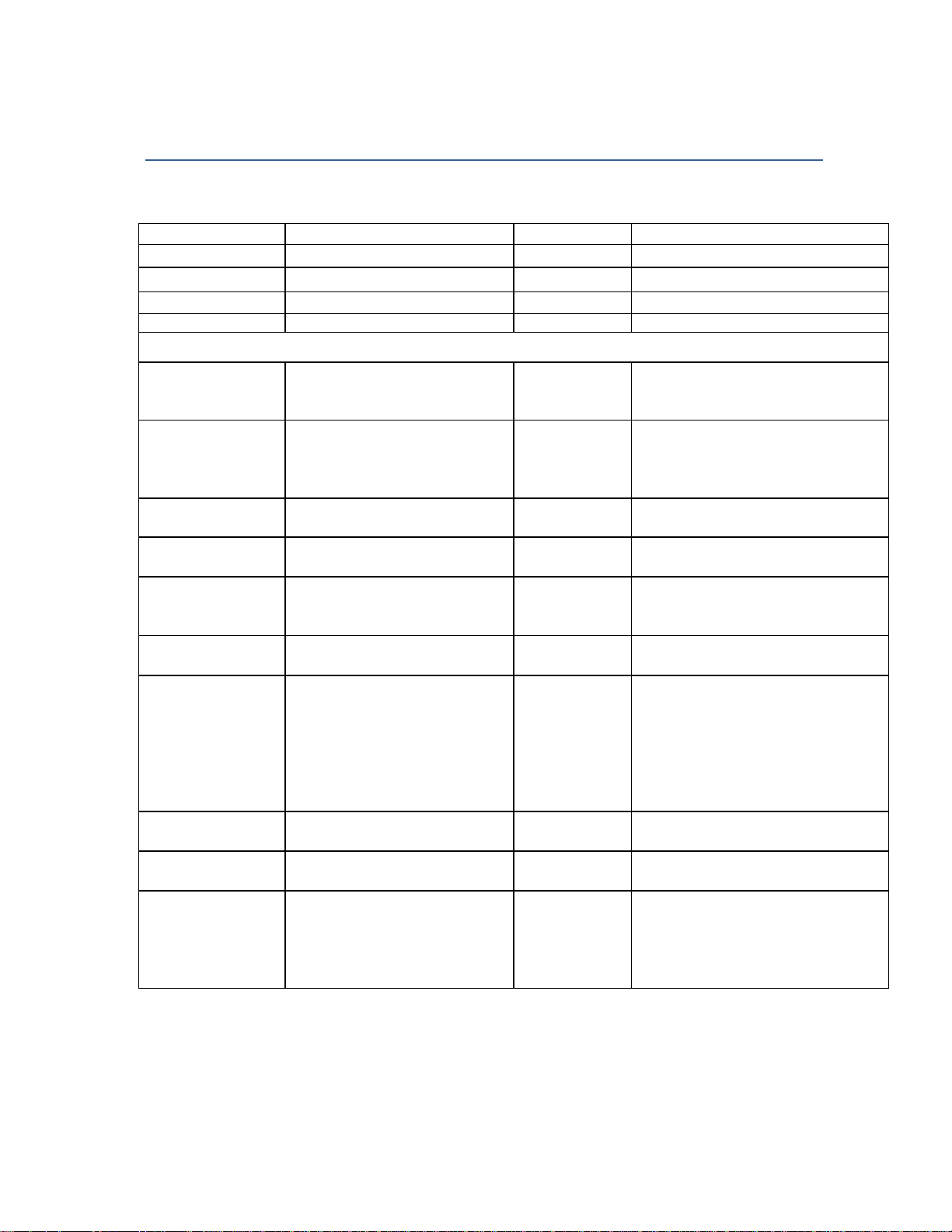
Ch a n ge S e t u
p Ch a n ge d e f a u lt pa ra me t er s
En t er ac c es s c o de
s t a mp e d.
he l p p re s er ve b at t e r y l if
e
nf i rm ed P um p r es et s t o t h is
pr o g r a m m in g ) . Wh en P ro gr a m
du r at io n o r r a te du ri n g s et u p
16/06/2007
T34 SYRINGE PUMP DEFAULT SETTINGS
The pump is programmed with a number of default parameters that can be changed using "Change Set
Up" from the Info menu and using the Change Set up Access Code
PA RAME TER PURPO SE Defau lt RANGE
Ex i t Ex i t t h e In f o Mo d e Pr e s s YF S k ey
B a t t e r y L e ve l C ur r e n t b at t er y l ev e l Em p t y » F u ll
Ev e n t Lo g La s t 5 12 e v en t s In t o f o r f ul l d i s c lo s ur e
.
Change Setup mode access with code (99)
En s u r e s a l l e v e n t s i n lo g a r e
Ti m e & D a te
I I K e y Op er at i on
B a c kl i gh t D u ra t i o n
co r r e c t l y d at e a n d t im e
Li m i ts t h e f or w ar d m o ve m e n t
of ac t u a t o r c a us e d by
pr e s si ng th e F F k ey du r in g
s y r in ge l oa di n g
Li m i ts b a ck l ig h t d u r a t i on to
Da y . M o nt h. Ye a r. Hr s . M i ns .
2 m m 0. 1 - 10 0 mm
5 s ec 0 - 6 0s ec s .
In f o D u r at i o n
Op e r at io n L TD
Ti t r a t io n O p ti on
De f a u l t D ur at i on
Oc c l us io n P r es su r e
K V O O p er a ti on
Pr o gr am Lo c k
Li m i ts t h e l en g th of t i m e t h e
In f o s c r e en is di s pl ay e d
Tu r n s of f t h e gr e b e f l a sh in g
op e r a t io n I ) t o p r es e r v e
ba t t e r y l if e
En a b l e s s et t i n g a t it r at i on
li m i t wi t h i n m ax . r a te ra ng e
Wh e n a n ew p ro g ra m i s
co
de f au l t ( se t ti n g t o z er o s k i p s
du r at io n s t ep du r in g
Lo c k O N ( s e e b el o w ) c a n no t
be s et t o z e r o .
Se t t in g a t w hi c h o cc l u s i o n
al a r m w i l l a ct i va t e
Ac t i v at e s K ee p V e in O p en
in f us i o n at E n d o f I nf u si on
Pr e ve n ts al t er at i on o f e i th e r
(w i t h Pr o gr am Lo c k O N
De f a u l t D ur at i o n ca n no t b e
s e t t o z e ro )
5 s ec I - 2 0s ec s .
3 2 s e c. D i sa b le . 2 .4 . 8 . 1 6 . 3 2 . 6 4s ec
di s ab l ed En ab le d /D i s a bl e d
2 4 H o ur s 0 0 :0 1 t o 9 9 :0 0 h ou r s
5 4 0 m mH « 10 0 - 1 5 0 0 m m ll g
Dis ab l ed En ab l e d /D i s a bl e d
ON O N/ OF F
43
Page 44
Service & Repair Manual
PARAME TER
PU RPOSE
Defau lt
RA NGE
Ca l i br at i on
ca l
ib r a t ed f or c e g au g es
16/06/2007
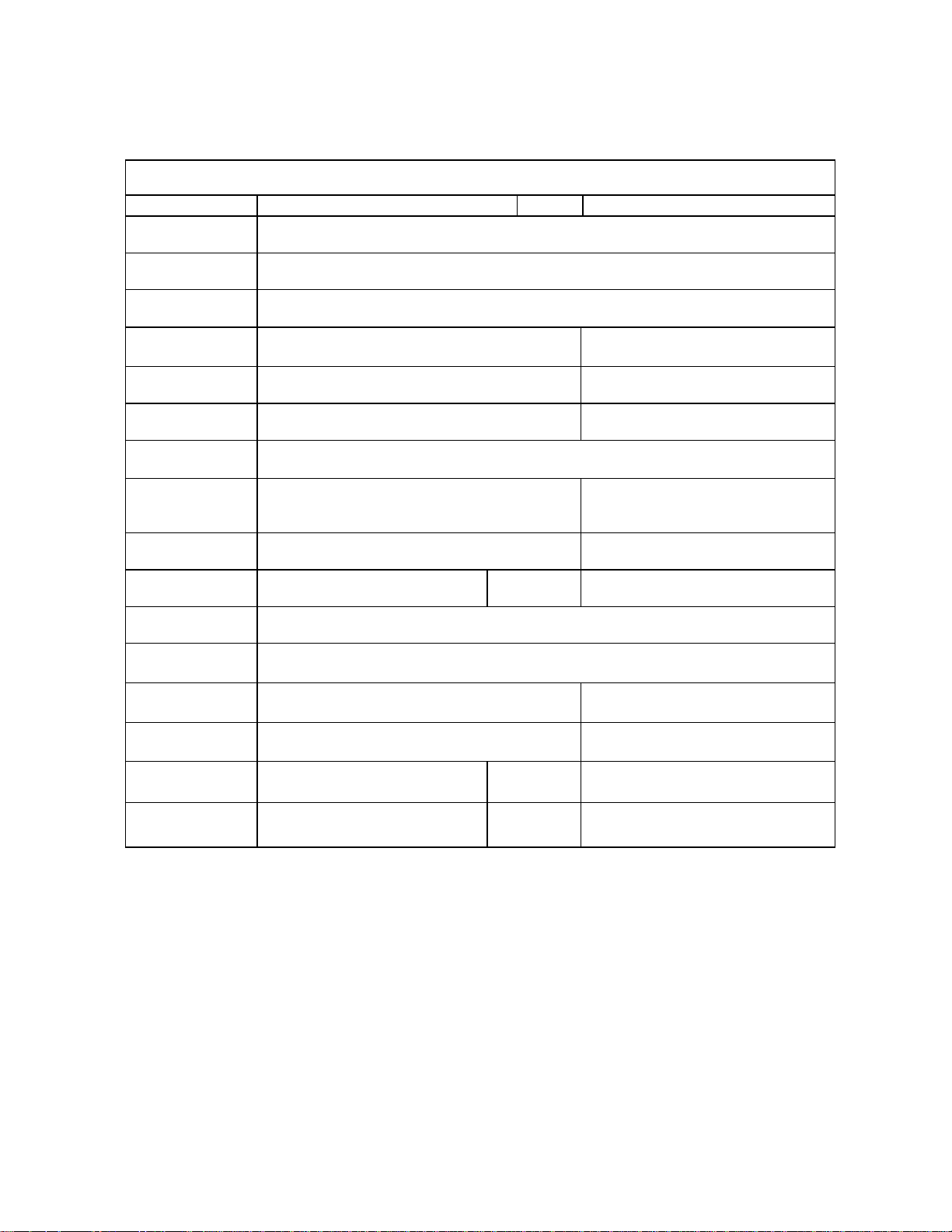
Technician Mode (123)
Se r i al n u mb e r/
Pr o d uc ti o n d at e
Ma i n S el f Te st
Ma n u a l T es t
Sy r in g e S et u p
Pr e s s ur e
Fa c to r y P re s s.
Te s t
Pr e s s ur e T es t T es t r o ut in e t o e n su r e p r es s ur e c a li b ra t i o n i s w it h in s p ec i fi c at io n s
Sy r in g e T ra v e l
Di a m e t er
Ca l i br at i on
Sy r in g e D ea d
Sp a ce
Vo l u m e T es t Ca n be s e t t o a ny vo lu m e a t an y f l ow r a t e
Fa c to r y s et ti n gs C A U T I O N : R ES ET AL L S E TT I N G S T O D E F A U L T
Un i qu e I D n u mb er a n d d a te pu mp w a s p r od u ce d ( W ee k N o . M o nt h & Ye a r)
Au t o ma ti ca l ly s e q ue n ce s t h ro u gh th e f ol l ow i n g te s ts . K ey p ad , D is p la y ,
Ac o u s t ic Al ar m , S yr i ng e s en s or s , Di a me t er , P o w er vo l ta ge
Al l o ws m a nu al s e l ec t io n o f t h e a bo ve te s ts
Ad d or D e le t e s yr i n g e s f ro m t h e d e f au lt
li s t
Pr e s s ur e c a li b ra ti o n r ou ti n e u si n g t he
Te s t r ou t in e t o f in e t u n e th e p r e s s u r e
ca l ib r at i on s , us i ng a 5 ml & 5 0m l s yr in g e
Se t s u p t he Vo l um e s en s in g s ys t em b y
en s u ri n g th e C P U k n o ws t h e p os i ti o n o f
th e ac t ua to r
Se t up th e s yr i ng e r e co gn i ti o n s ys te m
11 m m
Se e AD DI N G/ D EL E TI N G a s yr i n g e
Se e PR ES S UR E C AL I B R A TI O N
Se e PR ES S UR E C AL I B R A TI O N
Se e SY RI N GE TR A VE L
CA L I BR AT I ON i n t hi s m an u al
Se e DI A MT E R C AL I B R A T I ON in
th i s m an u al
Op e r at in g H o ur s Nu m b e r o f h o u r s i n U se
Se r vi c e i nt e rv al s
Pu r g e Vo l um e
Ma x i mu m R at e
Wa r n i n g c an b e s e t w h e n a p r es et n um b er
of op e r a t in g h o ur s h as be e n r ea c he d
Re d u c e t h e s ta r t up t i m e
Ma x i m u m f lo w r at e t h e p um p
wi l l o p er at e
Ca n be re s et b y p r es s in g t h e NO
ke y
0 - 5 00 00 h r s
0 . 2 m l 0- . 5 ml
5 m l / h r 0. 0 5 -6 5 0m l/ h r
44
Page 45

Service & Repair Manual
16/06/2007
LIMITED WARRANTY
The T34 Syringe pump has been carefully manufactured from the highest quality components.
Barak Medical Electronics Ltd. (BMP.) guarantees the pump against defects in material and workmanship
for twelve (12) months from date of purchase by the original purchaser.
BMH's obligation, or that of its designated representative under this Limited Warrant), shall be limited, at
BME's option, or that of its designated representative to repairing or replacing pumps, which upon
examination, are found to be defective in material or workmanship. The repair or replacement of an\
product under this Limited Warranty shall not extend the above-mentioned Warrant) period.
Only qualified, trained service personnel should undertake all repairs under this Limited Warrant). In the
event that a pump is found to be defective during the warranty period, the purchaser shall notify BME or
its designated representative within thirty (30) days after such defect is discovered.
The defective pump should be sent immediately to BME or its designated representative for inspection,
repair or replacement. Mailing costs are the purchaser's responsibility.
Material returned to BME or its designated representative should be properly packaged using BMP
shipping cartons and inserts. Inadequate packaging may result in severe pump damage.
This Limited Warranty shall not apply to defects or damage caused, wholly or in part, by negligence, spilt
fluids, dropping of the pump, misuse, abuse, improper installation or alteration by anyone other than
qualified, trained personnel; or to damage resulting from inadequate packaging in shipping the pump to
BME or its designated representative.
If, after inspection, BME or its designated representative is unable to identify a problem. BME or its
designated representative reserves the right to invoice purchaser for such inspection.
This Limited Warranty is the sole and entire warranty pertaining to BME's products and is in lieu of and
excludes all other warranties of any nature whatsoever, whether stated, or implied or arising by
operation of law, trade, usage or course of dealing, including but not limited to warranties of
merchantability and warranties of fitness for a particular purpose. Purchaser expressly agrees that the
remedies granted to it under this limited warrant)' are purchaser's sole and exclusive remedies with
respect to any claim of purchaser arising under this Limited Warranty.
Managing Director
45
Page 46
Service & Repair Manual
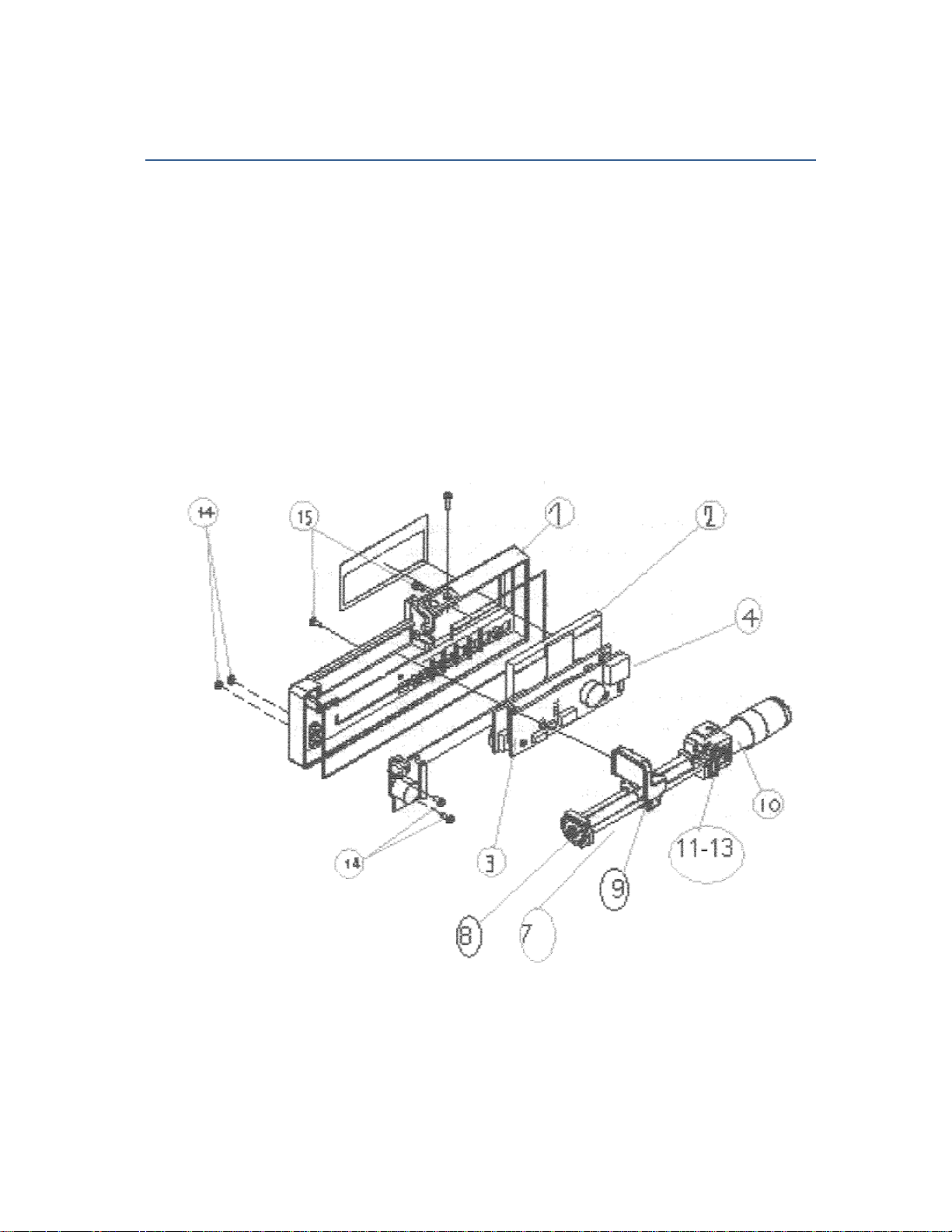
DRAWINGS
FRONT ASSEMBLY
1 - FRONT HOUSING
2- LCD DISPLAY
3- PCB MOTOR B
4- PCB MAIN A
7- REAR BLOCK
8- ACTUATOR
9- MOTOR
10- FRONT BLOCK
11- MOTOR ADAPTOR
12- MAGNET
13- M2X5 SCREWS
14- M2 NUTS
16/06/2007
46
Page 47
Service & Repair Manual
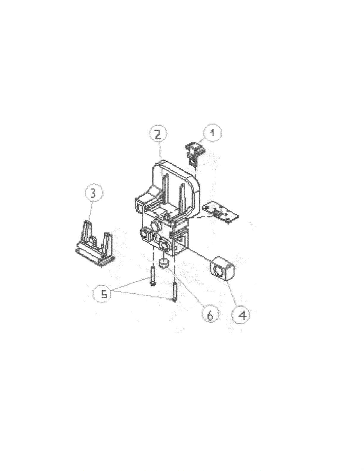
ACTUATOR ASSEMBLY
1 - ACTUATOR FIXER 2
2- ACTUATOR HOUSING
3- ACTUATOR FIXER 1
4- ACTUATOR ADAPTOR
5- ACTAUTOR CONTACT
6- MAGNET
16/06/2007
47
Page 48
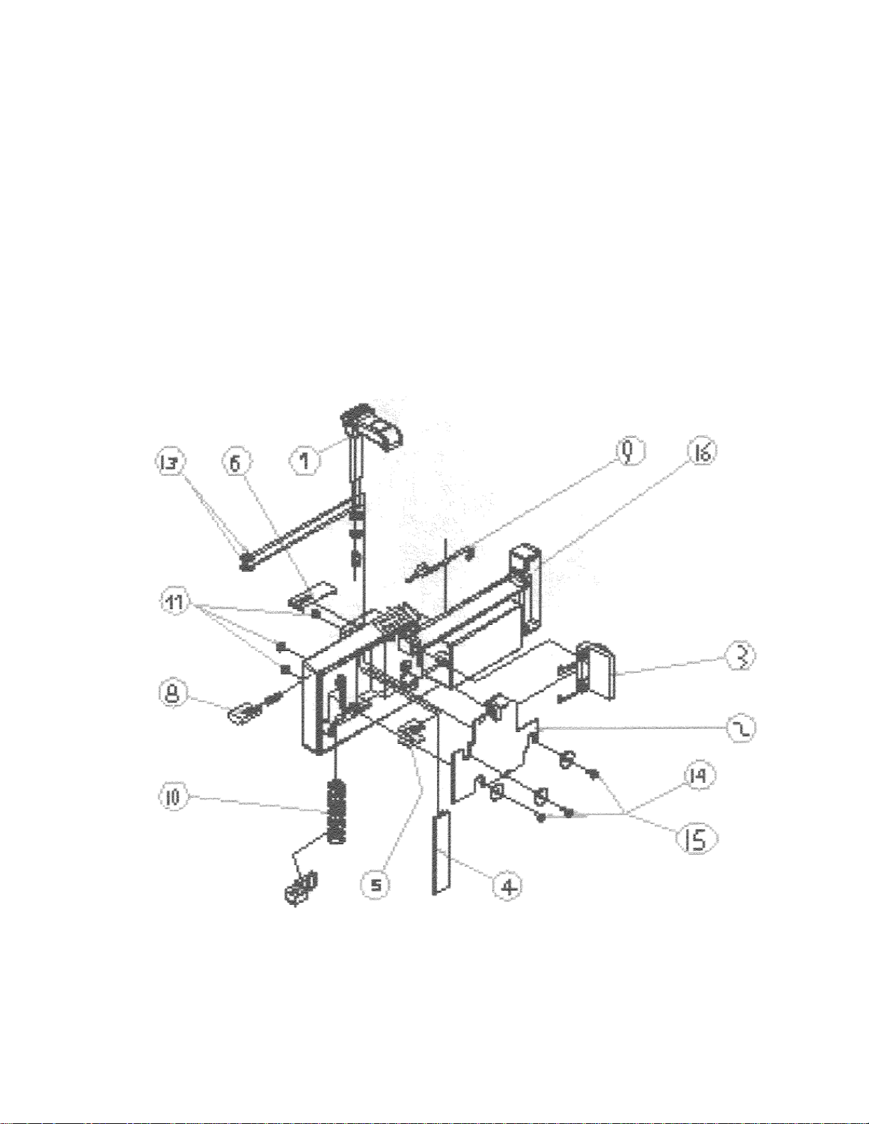
Service & Repair Manual
REAR ASSEMBLY
1 - SYRINGE HOLDER
2- REAR PCB D
3- WALL CONTACT
4- SYRINGE HOLDER COVER
5- POTENTIOMETER ADAPTOR
6- METAL COVER
8- SPRING HOUSING
9- FRONT SENSOR
10- HOLDER SPRING
11- M2 NUTS
13- E-RING
14- M2X3 SCREWS
15- PLASTIC WASHER
16- BATTERY COMPARTMENT
16/06/2007
48
Page 49
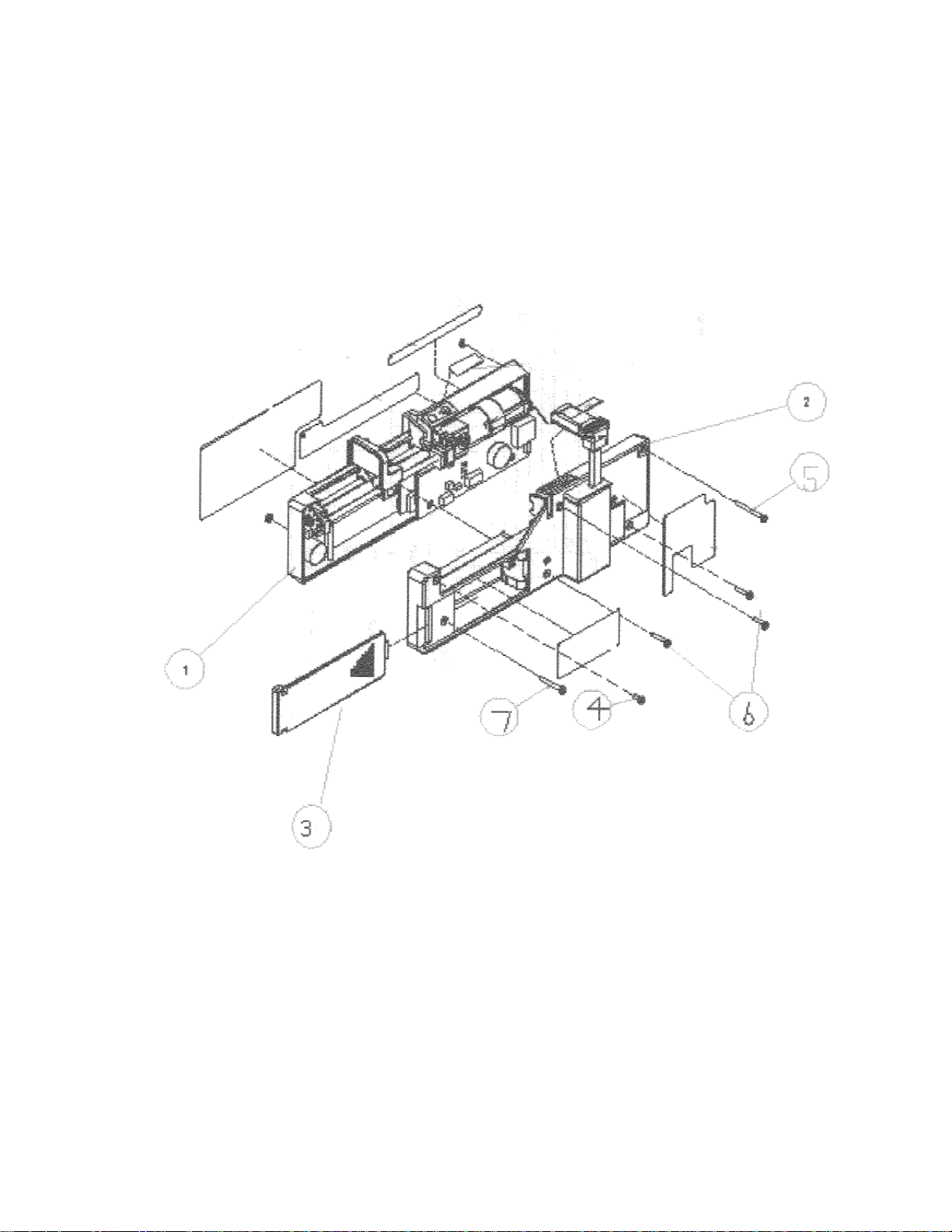
Service & Repair Manual
PUMP ASSEMBLY
1 - FRONT HOUSING
2- REAR HOUSING
3- BATTERY COVER
4- SCREWS M2X5
5- SCREWS M2X20
6- SCREWS M2X10
7- SCREWS M2X18
16/06/2007
49
Page 50
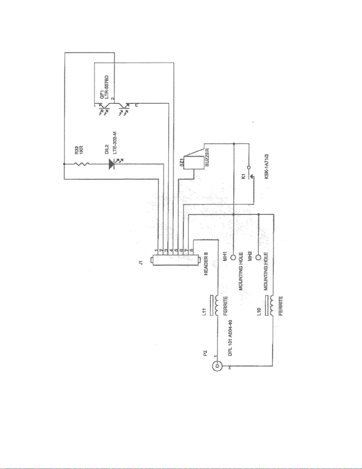
Service & Repair Manual
16/06/2007
50
Page 51
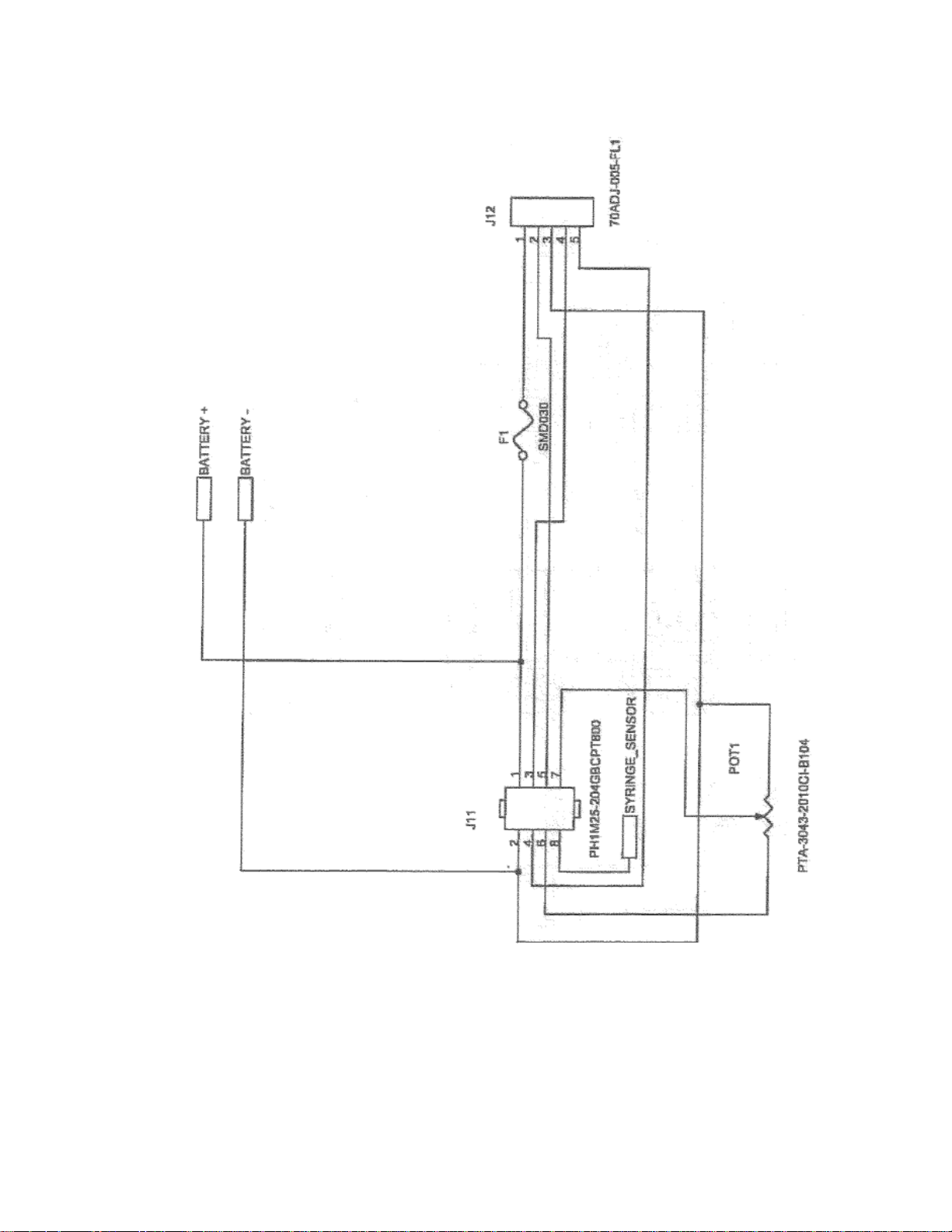
Service & Repair Manual
16/06/2007
51
Page 52
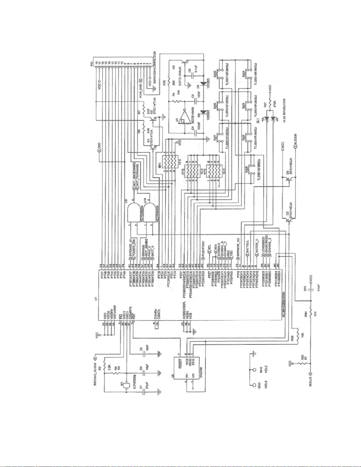
Service & Repair Manual
16/06/2007
52
Page 53
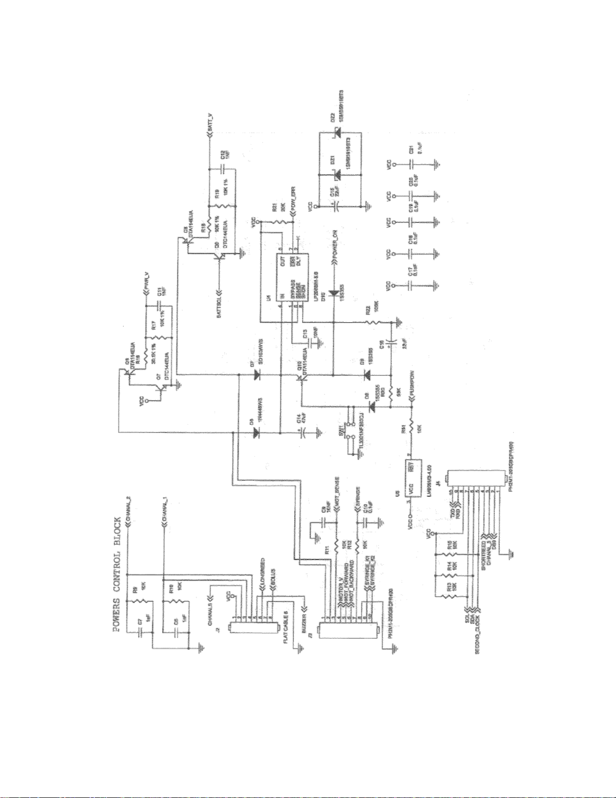
Service & Repair Manual
16/06/2007
53
Page 54
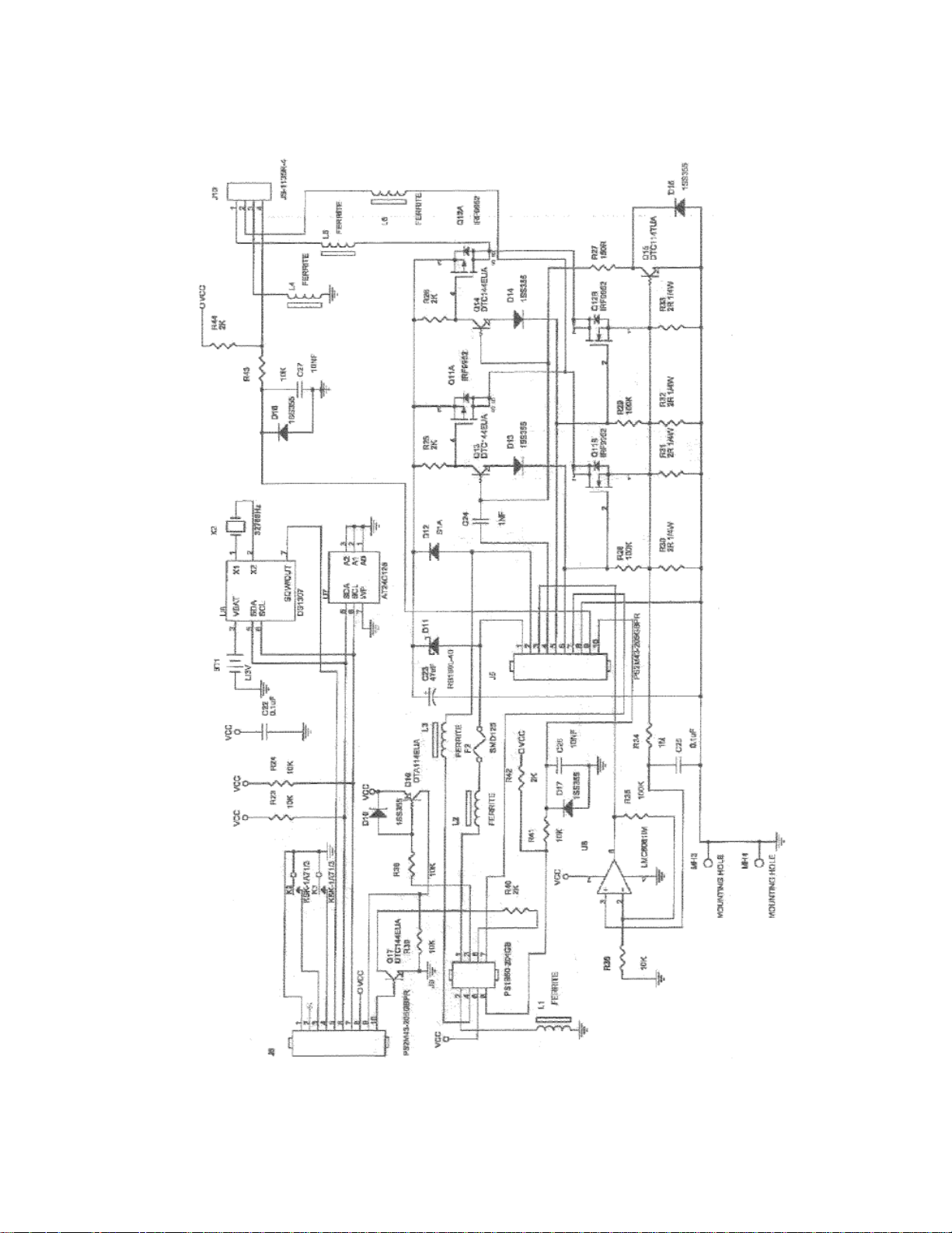
Service & Repair Manual
16/06/2007
54
Page 55
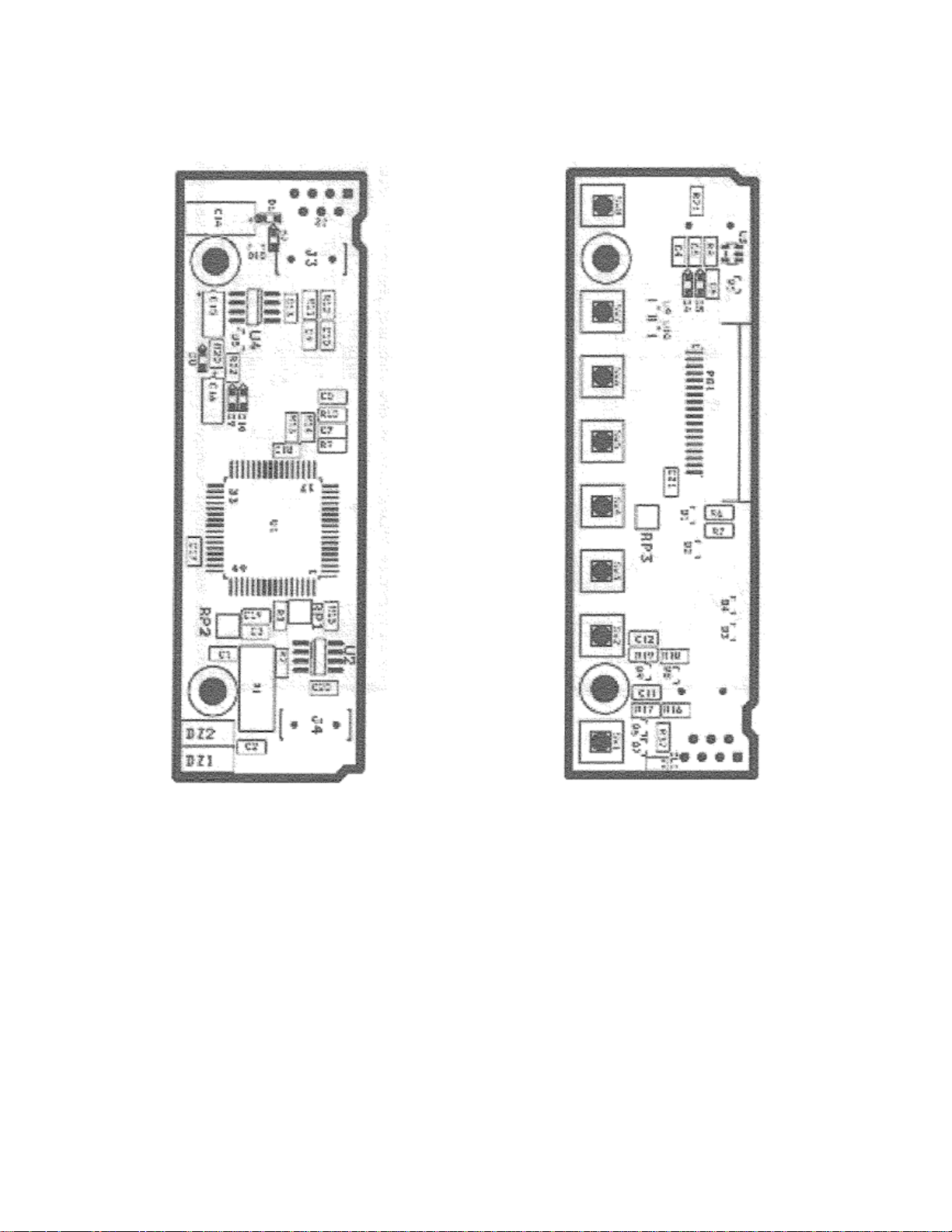
Service & Repair Manual
16/06/2007
MAIN PCB - REAR MAIN PCB - FRONT
55
Page 56
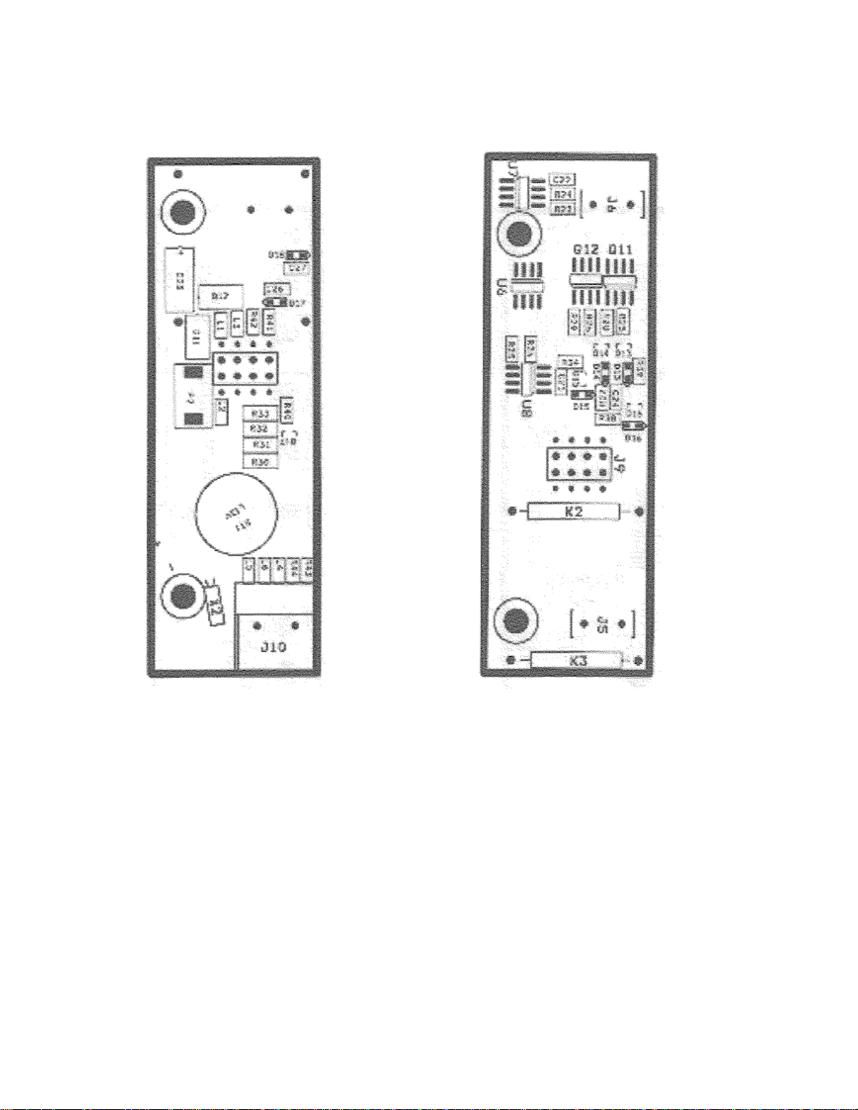
Service & Repair Manual
16/06/2007
MOTOR PCB – FRONT MOTOR PCB – REAR
56
Page 57
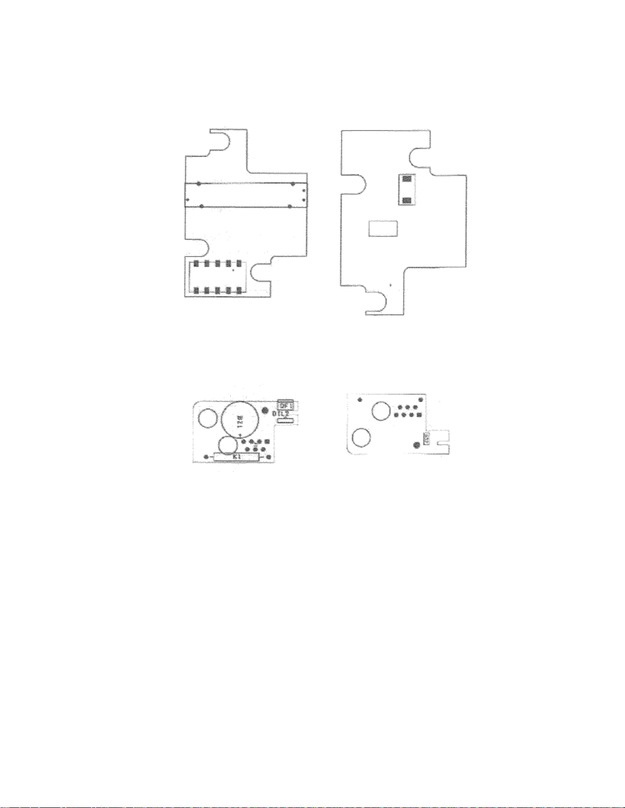
Service & Repair Manual
16/06/2007
REAR PCB – REAR REAR PCB – FRONT
ENCODER PCB – REAR ENCODER PCB – FRONT
57
Page 58

Service & Repair Manual
MAIN PCB
# QUANTITY
REFERENCE
DESCRIPTION
1 1 --- SYRINGE MAIN PCB VERSION
3
2 1 C1 Ceramic capacitor 27pf 5%
3 1 C2 Ceramic capacitor 16pf 5%
4 1 C3 Ceramic capacitor 18nf 10%
5 1 C4 Ceramic capacitor 100pf 5%
6 3 C5, C9, C13
Ceramic capacitor 10nf 10%
7
Alternative
Alternative
Ceramic capacitor 10nf
5%
8 7 C6, C10, C17, C18, C19, C20, C21
Ceramic capacitor
0.1µf 20%
9
Alternative
Alternative
Ceramic capacitor
0.1µf +80
-20% 50v
10 4 C7, C8, C11, C12
Ceramic capacitor 1nf 2
0%
11
Alternative
Alternative
Ceramic capacitor 1nf 10%
12 1 C14 Tantalum capacitor 47µF 16V
13 2 C15, C16
Tantalum capacitor 22µF 16V
14 1 DL1 19-22SRVGC/TR8
15 2 DZ1, DZ2
Diode Zener 1SMB59
19BT3
16 5 D4, D5, D8, D9, D10
Diode 1SS355
17 1 D6 IN4448WS
18 1 D7 SC103AWS
-7-F
19 2 J3, J4
PH2M15
-
205GBCPR400
20 1 PG1 Display connector 18P 52271
-
1890
21
Alternative
Alternative
FPC3AMR5
-
18TNB
-
18P
22 2 Q1, Q2
Transistor DTC114TUA
23 5 Q3, Q4, Q
6, Q8, Q10
Digital Transistor PNP DTA114EUA
24 1 Q5 DDTC124XUA (diodes)
25 2 Q7, Q9
Digital Transistor 47K NPN DTC144EUA
26 3 RP1, RP2, RP3
Resistor Net 10K
27 1 R2 Resistor 1M 5%
28 1 R3 Resistor 3.9K 5%
29 2 R6, R7
Resistor 51 5%
30 2 R8, R2
0 Resistor 56K 5%
31 7 R9, R10, R11, R12, R12, R14, R15
Resistor 10K 5%
32 1 R16 Resistor 30.1K
1%
33 3 R17, R18, R19
Resistor 10K
1%
34 1 R21 Resistor
20K 5%
35 1 R37 Resistor
470 5%
36 1 R22 Resistor
100K 5%
37 8 SW1
– SW8 Switch. TS
-
06j-AHM
38 1 U1 Microprocessor MC908AZ60ACFU
39 1 U2 SP706EN
40
Alternative
Alternative
MAX706ESA
41 1 U3 NC7S14M5X
42
Alternative
Alternative
BUAS584
43 1 U4 LP29881M
-
5.0
44 2 U5 LM809M3
-
4.00
45 1 U9, U10
NC7S08P5X
46 1 X1 Crystal
– 4.9152 MHz M
49L
16/06/2007
BILL OF MATERIALS
58
Page 59

Service & Repair Manual
MOTOR PCB
# QUANTITY
REFERENCE
DESCRIPTION
1 1 --- SYRINGE
MOTOR
PCB VERSION
3
2 2 C22, C25
Ceramic capacitor
0.1µf 20%
3
Alternative
Alternative
Ceramic capacitor 0.1µf +80
-
20% 50v
4 1 C23 Tantalum capacitor 47µF 16V
5 1 C24 Ceramic capaci
tor 1nf 20%
6
Alternative
Alternative
Ceramic capacitor 1nf 10%
7 2 C26, C27
Ceramic capacitor 10nf 10%
8
Alternative
Alternative
Ceramic capacitor 10nf 5%
9 1 D11 Diode schottky RB160L
-
40 1A
10 1 D12 Diode S1G
11
Alternative
Alternative
Diod
e S1M
12 6 D13, D14, D15, D16, D17, D18
Diode 1SS355
13 1 F2 Fuse SMD
-
125-2
14 2 J5, J6
PS2MM43
-
205GB
BPR
15 1 J9 PS1B50-20GB
16 6 L1, L2, L3, L4, L5, L6
Ferrite
–
FR BD 600R 25%
17 2 Q11, 12
IRF9952 double MOSFET
18
Alternative
Alternative
IRF7309
19
Alternative
Alternative
MMDF2C03HD double MOSFET
20 3 Q13, Q14, Q17
Digital transistor 47K NPN DTC144EUA
21 1 Q15 Digital transistor 10K NPN DTC114TUA
22 1 Q16 Digital transistor PNP DTA114EUA
23 7 R23, R34, R36, R38, R39, R41, R43
Resistor 10K 5%
24 5 R25, R26, R40, R42, R44
Resistor 2K 5%
25 1 R27 Resistor 150 5%
26 3 R28, R29, R35
Resistor 100K 5%
27 4 R30, R31, R32, R33
Resistor ¼ W 2 5%
28 1 R34 Resistor 1M 5%
29 1 U6 DS1307Z
30 1 U7 CAT 24WC128
31
Alternative
Alternative
24LC1
28-I/SN
32 1 U8 LMC6061IM
33 1 BT1 3V Lithium battery
34 1 J10 Connector, 4p male 2.5mm 900
35 2 K2, K3
Reed switch KSK
-
1A71/3
-
BV13583
36 1 X2 CRYSTAL 32768Hz 2X6 15PPM
16/06/2007
59
Page 60

Service & Repair Manual
ENCODER PCB
# QUANTITY
REFERENCE
DESCRIPTION
37 1 --- SYRINGE
ENCODER
PCB
38 1 BZ1 Buzzer TDB 05
39 1
DIL2 LTE-302-M
40 1 K1 Reed switch KSK
-
1A71/3
-
BV13583
41 1 QF1 LTR-5576D
42 1 R32 Resistor 1
K 5%
REAR
PCB
# QUANTITY
REFERENCE
DESCRIPTION
43 1
--- SYRINGE
REAR
PCB
44 1
--- Connector
70ADJ-005-FL1
45 1
--- Connector PH1M25-204GBCPT800
46 1
--- Potentiometer PTA-3043-2010CI-B104
16/06/2007
60
 Loading...