

Page 1
User Manual
Auto CPAP / CPAP System
G2S A20 / G2S C20
0123
Page 2

G2S A20 / G2S C20 User Manual V1.0
Table of Contents
1. Symbols ·································································································· 1
1.1 Control Buttons ················································································ 1
1.2 Device Symbols ················································································ 1
2. Warning, Caution and Important Tip ······························································· 3
3. Intended Use ···························································································· 3
4. Contraindications ······················································································· 4
5. Specifications ···························································································· 5
6. Available Therapies ····················································································· 7
7. Glossary ·································································································· 7
8. Model ····································································································· 8
9. Package Contents ······················································································· 9
10. System Features ······················································································ 10
11. First Time Setup ······················································································ 11
11.1 Placing the Device ·········································································· 11
11.2 Installing the Air Filter and Filter Cap ··················································· 12
11.3 Connecting to Power ······································································· 12
11.4 Assembling the Tube and Mask ·························································· 13
11.5 Using Oxygen with the Device ··························································· 14
11.6 Inserting the SD Card (Only for the device that equipped with SD card) ········ 15
11.7 Using the Cellular Module ································································· 16
11.8 Starting Treatment ········································································· 16
12. Routine Use ··························································································· 16
12.1 Connecting the Tube ······································································· 16
12.2 Adjusting the Tube ········································································· 16
12.3 Turning on the Airflow ····································································· 16
12.4 Heating the Water in the Humidifier ···················································· 16
12.5 Using the Ramp Button ···································································· 17
12.6 Turning the Device Off ····································································· 17
13. Heated Humidifier ··················································································· 17
13.1 Filling the Water Chamber ································································ 17
13.1.1 Removing the Water Chamber ················································· 17
13.1.2 Filling Water ································································ ······· 17
13.1.3 Inserting the Water Chamber ·················································· 18
13.2 Emptying the Water Chamber ···························································· 19
13.3 Setting the Humidity Level ································································ 19
14. Navigating the Patient Menu ······································································· 20
14.1 Steps to Navigating the Patient Menu ·················································· 20
14.1.1 Accessing the Main Interface ·················································· 20
14.1.2 Bringing up the Initial Setup Interface ······································· 21
14.1.3 Accessing the Setup Interface ················································· 21
14.1.4 Selecting Options ································································· 21
14.1.5 Adjusting Options ································································ 22
14.1.6 Confirming Adjustments ························································ 22
14.1.7 Turning Pages ····································································· 22
14.1.8 Exiting the Patient Menu ························································ 22
14.2 Options of the Patient Menu and Corresponding Descriptions ····················· 24
15. Alert ···································································································· 25
16. Cleaning and Disinfection ··········································································· 26
16.1 Cleaning the Mask and Headgear ······················································· 26
16.2 Cleaning the Cellular Module ····························································· 26
16.3 Cleaning the Water Chamber ····························································· 26
16.4 Cleaning the Enclosure ···································································· 27
Page 3

G2S A20 / G2S C20 User Manual V1.0
16.5 Cleaning the Tube ·········································································· 27
16.6 Replacing the Air Filter ···································································· 28
16.7 Disinfection ·················································································· 28
17. Traveling with the Device ··········································································· 29
18. Transferring the Device to Another Patient ······················································ 30
19. Reordering ····························································································· 30
20. Technical Support ···················································································· 30
21. Disposal ································································································ 30
22. Troubleshooting ······················································································ 31
22.1 Common Problems in Patients and Corresponding Solutions ······················· 31
22.2 Common Problems in the Device and Corresponding Solutions ··················· 33
23. EMC Requirements ··················································································· 34
24. Limited Warranty ····················································································· 39
Page 4
G2S A20 / G2S C20 User Manual V1.0
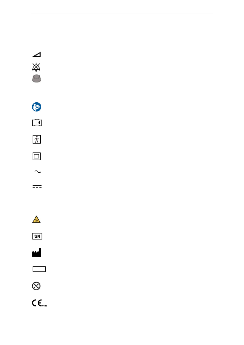
Ramp Button
Mute Button
Knob
Follow Instructions for Use
Operating Instructions
Type BF Applied Part (mask)
Class II (Double Insulated)
AC Power
DC Power
IP22
≥ 12.5 mm Diameter, Dripping (15ºtilted)
Hot Surface
Serial Number of the Product
Manufacturer
EC
REP
Authorized Representative in the European Community
Disassembly is prohibited
European CE Declaration of Conformity
1. Symbols
1.1 Control Buttons
1.2 Device Symbols
1 / 39
Page 5
G2S A20 / G2S C20 User Manual V1.0
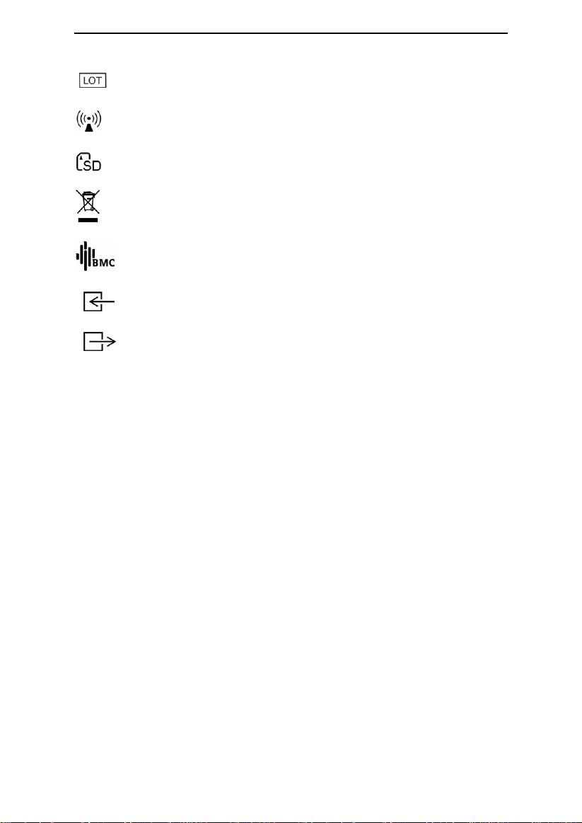
Lot number
Non-Ionizing Radiation
SD Card
WEEE Marking
Logo of BMC Medical Co., Ltd.
Air Inlet
Air Outlet
2 / 39
Page 6

G2S A20 / G2S C20 User Manual V1.0
2. Warning, Caution and Important Tip
WARNING!
Indicate the possibility of injury to the user or operator.
CAUTION!
Indicate the possibility of damage to the device.
IMPORTANT TIP!
Place emphasis on an operating characteristic.
Warnings, Cautions, and Important Tips appear throughout this manual as they apply.
3. Intended Use
The G2S A20 / G2S C20 system is a CPAP (Continuous Positive Airway Pressure) device
designed for the treatment of adult Obstructive Sleep Apnea (OSA) only, either in the
hospital or at home.
The device is to be used only on the instruction of a licensed health care professional. Your
home care provider will make the correct pressure settings according to your health care
professional’s prescription.
Several accessories are available to make your OSA treatment with this device as convenient
and comfortable as possible. To ensure that you receive the safe, effective therapy
prescribed for you, use only BMC accessories.
WARNINGS!
• This device is intended for adult use only.
• This device is not intended for life support.
• The instructions in this manual are not intended to supersede established medical
protocols.
• Do not bring the device or accessories into a Magnetic Resonance (MR) environment as it
may cause unacceptable risk to the patient or damage to the device or MR medical devices.
The device and accessories have not been evaluated for safety in an MR environment.
• Do not use the device or accessories in an environment with electromagnetic equipment
such as CT scanners, Diathermy, RFID and electromagnetic security systems (metal
detectors) as it may cause unacceptable risk to the patient or damage to the device. Some
electromagnetic sources may not be apparent, if you notice any unexplained changes in the
performance of this device, if it is making unusual or harsh sounds, disconnect the power
cord and discontinue use. Contact your home care provider.
CAUTIONS!
• This device is restricted to sale by or on the order of a physician.
• The patient is an intended operator.
3 / 39
Page 7

G2S A20 / G2S C20 User Manual V1.0
IMPORTANT!
• Read and understand the entire user manual before operating this system. If you have any questions
concerning the use of this system, contact your home care provider or health care professional.
4. Contraindications
Studies have shown that the following pre-existing conditions may contraindicate the use of
positive airway pressure therapy for some patients:
Absolute Contraindications: Pneumothorax, mediastinal emphysema; cerebrospinal fluid
leak, traumatic brain injury, or pneumocephalus; shock caused by a variety of conditions
before treatment; active epistaxis; upper gastrointestinal bleeding before treatment; coma
or impaired consciousness making the use of mask during therapy impossible; giant vocal
fold polyp, etc.
Relative Contraindications: Severe coronary heart disease complicated with left
ventricular failure, acute otitis media, excessive respiratory secretions and weak cough, weak
spontaneous breathing, nasal or oral tracheal intubation and tracheotomy, severe nasal
congestion caused by a variety of conditions, lung bullae, and allergies to breathing masks,
etc.
The following side effects may occur during treatment:
- Dryness of the mouth, nose and throat
- Abdominal bloating
- Ear or sinus discomfort
- Eye irritation
- Skin irritation due to the use of a mask
- Chest discomfort
IMPORTANTS!
• An irregular sleep schedule, alcohol consumption, obesity, sleeping pills, or sedatives may
aggravate your symptoms.
• Please use a mask which meets ISO 17510: 2015.
CAUTION!
• Contact your health care professional if symptoms of sleep apnea recur. Contact your
health care professional if you have any questions concerning your therapy.
4 / 39
Page 8

G2S A20 / G2S C20 User Manual V1.0
5. Specifications
Device Size
Dimensions: 274 mm × 184 mm × 115 mm
Weight: 1.9 kg
Water capacity: To maximum fill line 360 mL
Product Use, Transport and Storage
Operation Transport and Storage
Temperature: 5°C to 35°C (41˚F to 95˚F) -25°C to 70°C (-13˚F to 158˚F)
Humidity: 15% to 93% Non-condensing 15% to 93% Non-condensing
Atmospheric Pressure: 760 ~ 1060 hPa 760 ~ 1060 hPa
Heated Humidifier
Humidifier Settings: off, 1 to 5 (95˚F to 154.4˚F / 35°C to 68°C)
Humidifier Output: No less than 10 mg H2O/L
Environmental Conditions: Maximum airflow, 35°C, 15% relative humidity
Mode of Operation
Continuous
Work Mode
CPAP, Auto
SD Card
The SD card can record patient data and fault information
AC Power Consumption
100 - 240 V ~, 50 / 60 Hz, Max 2 A
Device offer to USB Communications Port
5 V 2.0 A
Type of Protection Against Electric Shock
Class II Equipment
Degree of Protection Against Electric Shock
Type BF Applied Part
Degree of Protection Against Ingress of Water
IP22
Pressure Range
4 to 20 hPa (in 0.5 hPa increments), ≤30 hPa under single fault conditions.
Static Pressure Stability
± 0.5 hPa
Ramp
The ramp time ranges from 0 to 60 minutes.
5 / 39
Page 9
G2S A20 / G2S C20 User Manual V1.0
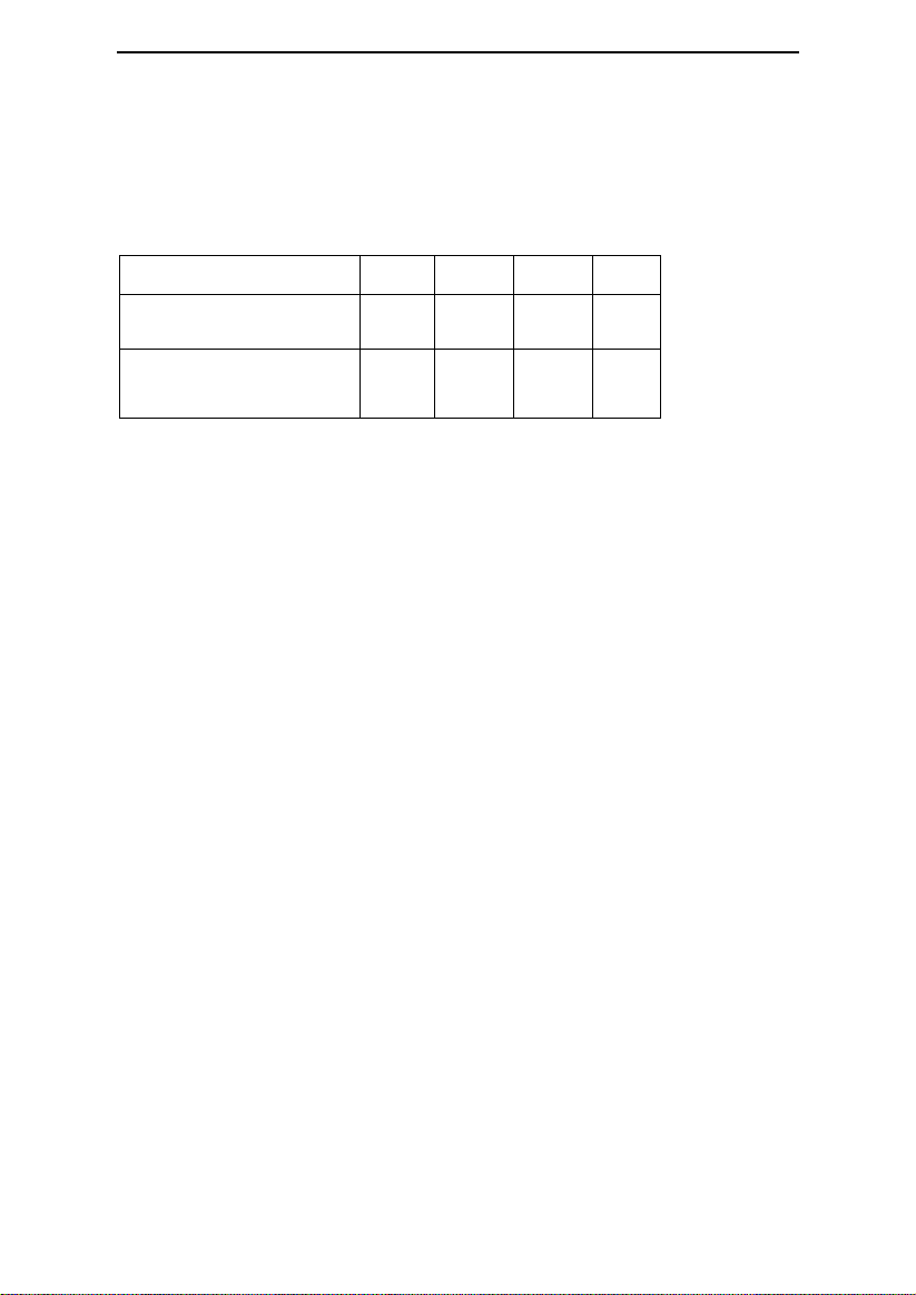
Test Pressures (hPa)
4
10
15
20
Measured Pressure at the
Patient Connection Port (hPa)
3 9 14
19
Average Flow at the Patient
Connection Port (L/min)
85
135
140
140
Sound Pressure Level
<28 dB, when the device is working at the pressure of 10 hPa.
Sound Power Level
<38 dB, when the device is working at the pressure of 10 hPa.
Maximum Flow
Automatic leak compensation
The pressure error ≤ ± 1 hPa when the air leakage is no more than 70 L / min.
Pressure
Range: 0 ~ 20 hPa
Margin of Error: ± (0.4 hPa + 4%)
Tube
Length: 6 ft. (1.83 m)
Maximum Delivered Gas Temperature
≤43°C
The Form and the Dimensions of the Patient Connection Port
The 22 mm conical air outlet complies with ISO 5356-1.
6 / 39
Page 10

G2S A20 / G2S C20 User Manual V1.0
6. Available Therapies
The device delivers the following therapies:
CPAP –
pressure throughout the breathing cycle. If your health care professional has prescribed
ramp for you, you can press the Ramp Button to reduce the pressure and then
gradually increase the pressure to the therapeutic pressure setting so that you can fall asleep
more comfortably.
Auto –
based on the patient’s needs.
Delivers Continuous Positive Airway Pressure; CPAP maintains a constant level of
Delivers CPAP therapy and provides an air pressure no less than the prescribed one
7. Glossary
Apnea
A condition marked by the cessation of spontaneous breathing.
Auto
Adjust CPAP pressure automatically to improve patient comfort based on monitoring of
apnea and snoring events.
Auto Off
When this feature is enabled, the device automatically discontinues therapy whenever the
mask is removed.
Auto On
With this feature, the device automatically initiates therapy when you breathe into the mask.
This feature is always enabled.
CPAP
Continuous Positive Airway Pressure.
iCode
A feature that is intended to give access to compliance and therapy management information.
The “iCode” consists of six separate codes displayed in the Patient Menu, each code is a
sequence of numbers. The “iCode QR” and “iCode QR+” display two-dimensional codes.
LPM
Liters Per Minute.
OSA
Obstructive Sleep Apnea.
Patient Menu
The display mode in which you can change patient-adjustable device settings, such as the
starting pressure for the Ramp feature.
7 / 39
Page 11
G2S A20 / G2S C20 User Manual V1.0
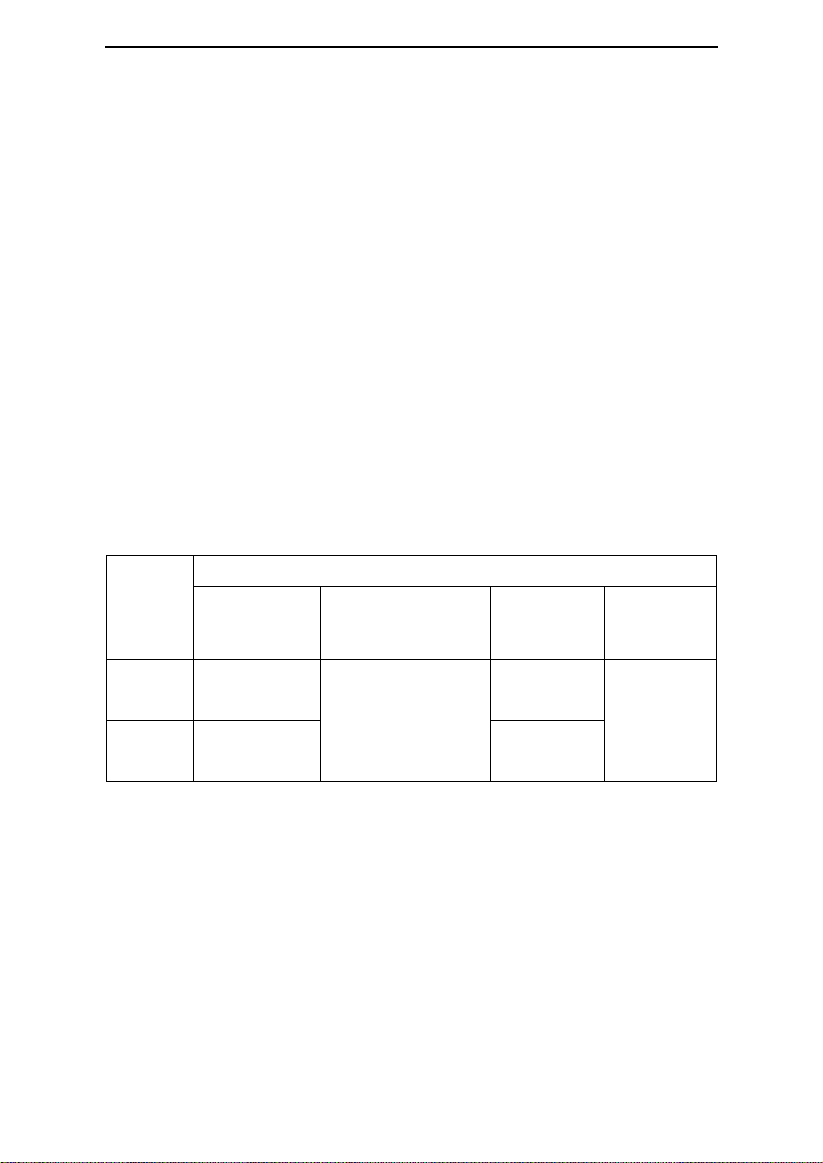
Model
Product Description
Product
Contents
Optional Accessory
Work Mode
Maximum
Work
Pressure
(hPa)
G2S A20
Device
(2.4-inch TFT)
Tube, Mask,
Cellular Module
CPAP,
Auto
20
G2S C20
Device
(2.4-inch TFT)
CPAP
Ramp
A feature that may increase patient comfort when therapy is started. It can reduce pressure
and then gradually increase the pressure to the prescription setting so the patient can fall
asleep more comfortably.
Reslex
A therapy feature that is enabled by your home care provider to provide pressure relief
during exhalation.
Standby State
The state of the device when power is applied but the airflow is turned off.
min
Means the time unit “minute”.
h
Means the time unit “hour”.
yy mm dd / mm dd yy / dd mm yy
Denotes date.
8. Model
8 / 39
Page 12
G2S A20 / G2S C20 User Manual V1.0
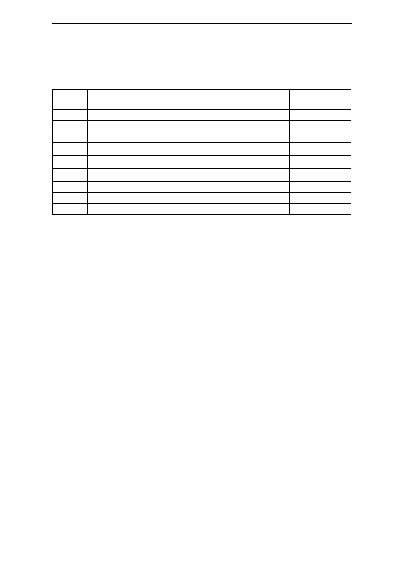
No.
Articles
Qty.
Notes
1
Device
1
2
Air Filter
2
3
Power Adapter
1
4
Power Cord
1
5
Mask
1
Optional
6
Cellular Module
1
Optional
7
Tube
1
Optional
8
SD Card
1
Optional 9 Carrying Case
1
Optional
10
Enclosed Documents
1
9. Package Contents
After unpacking the system, make sure you have everything shown here (Different models of
the product may contain different components):
All parts and accessories are not made with natural rubber latex.
The product’s service life is five years if the use, maintenance, cleaning and disinfection are
in strict accordance with the User Manual. If the key components are replaced, the service
life may be prolonged.
IMPORTANTS!
• If any of the above parts are missing, contact your home care provider.
• Contact your home care provider for additional information on the available accessories of
this device. When using optional accessories, always follow the instructions enclosed with
the accessories.
• The tube with a diameter of 15mm or 22mm is available.
WARNINGS!
• This device should only be used with the mask and accessories manufactured or
recommended by BMC or with those recommended by your prescribing physician. The use of
inappropriate masks and accessories may affect the performance of the device and impair
the effectiveness of therapy.
• The use of accessories other than those specified, with the exception of cables sold by the
manufacturer of the equipment or system as replacement parts for internal components,
may result in increased emissions or decreased immunity of the equipment or system.
• Do not pile up the long tubing at the head of the bed, as it may wrap around the head or
neck of the patient during sleep.
• Do not connect any equipment to the device unless recommended by BMC or your health
care provider.
• Please contact BMC to obtain an SD card if needed.
9 / 39
Page 13
G2S A20 / G2S C20 User Manual V1.0
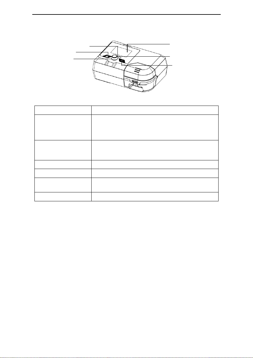
Humidifier Indicator
Mute Button
Knob
Ramp Button
Display Screen
Power Indicator
Name
Function
Humidifier Indicator
Indicate the humidity level. There are five levels in total. The
number of indicator lights that light up is directly proportional
to the humidity level. If the indicator lights are off, it means
the humidifier is turned off
Mute Button
Press this button to mute the alert. However, if the problem
causing the alert is not solved, the alert will sound again
two minutes later
Knob
Start treatment and adjust device settings
Ramp Button
Enable the Ramp feature
Display Screen
Display menus for operation, messages, monitoring data,
etc.
Power Indicator
Indicate the power supply status
10. System Features
Fig. 10-1
10 / 39
Page 14
G2S A20 / G2S C20 User Manual V1.0
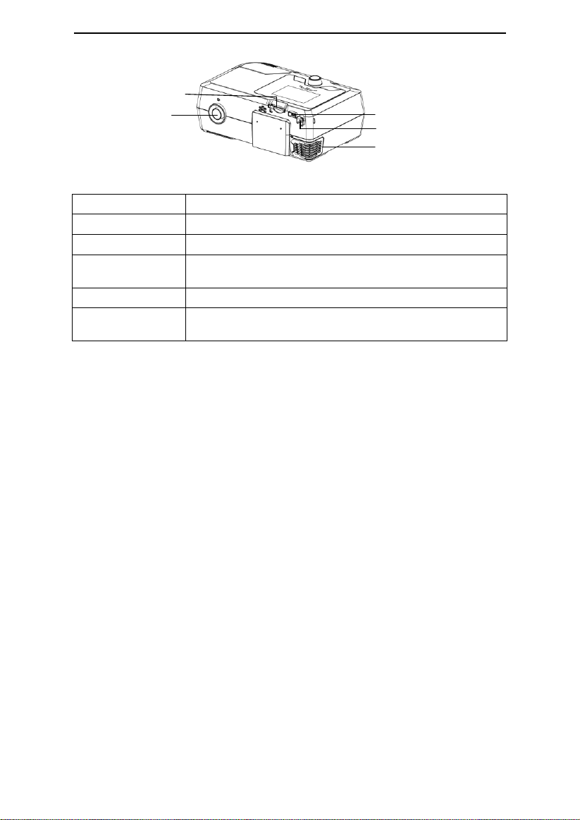
SD Card Slot
Communications Port
DC Inlet
Filter Cap (Air Inlet)
Air Outlet
Name
Function
SD Card Slot
Insert the SD card into this slot
Air Outlet
Deliver pressurized air; connects to the tube
Communications Port
Connected to external equipment (Not for connection to
un-recommended devices)
DC Inlet
An inlet for the DC power supply
Filter Cap (Air Inlet)
Place the cap on the air filter, which is used to filter dust and
pollen in the air entering the device
11. First Time Setup
11.1 Placing the Device
Place the device on a firm, flat surface.
Fig. 10-2
WARNINGS!
• If the device has been dropped or mishandled, if the enclosure is broken, or if water has
entered the enclosure, disconnect the power cord and discontinue use. Contact your home
care provider immediately.
• If the room temperature is warmer than 95°F (35°C), the airflow produced by the device
may exceed 109.4°F (43°C). The room temperature must be kept below 95°F (35°C) while
the patient uses the device.
CAUTIONS!
• If the device has been exposed to either very hot or very cold temperatures, allow it to
adjust to room temperature (approximately 2 hours) before beginning setup.
• Make sure the device is away from any heating or cooling equipment (e.g., forced air vents,
radiators, air conditioners).
• The device is not suitable for use in high humidity environments. Make sure that no water
enters the device.
• Make sure that bedding, curtains, or other items are not blocking the filter or vents of the
device.
• Keep pets, pests or children away from the device and avoid small objects being inhaled or
swallowed.
• To avoid explosion, this device must not be used in the presence of flammable gases (e.g.
11 / 39
Page 15
G2S A20 / G2S C20 User Manual V1.0
Filter Cap
Air Filter
Power Adapter
Power Cord
DC Inlet
anesthetics).
• Tobacco smoke may cause tar build-up within the device, leading to the malfunctioning of the device.
• Air must flow freely around the device for it to work properly.
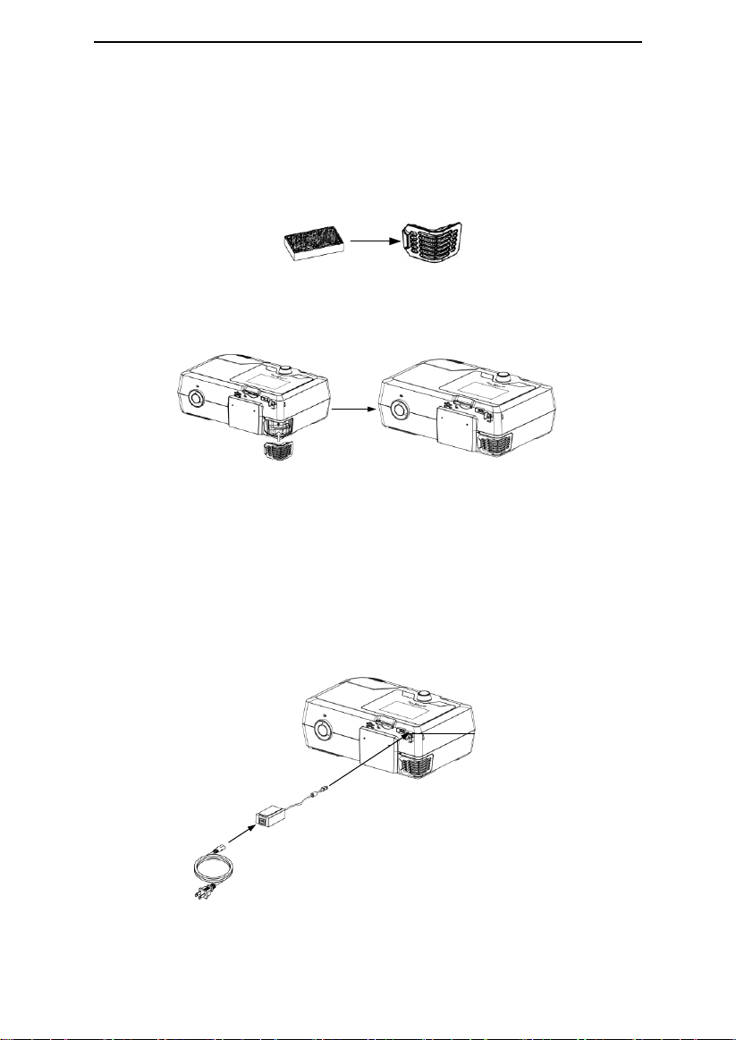
11.2 Installing the Air Filter and Filter Cap
(1) Attach the air filter to the filter cap, as shown in Fig. 11-1.
Fig. 11-1
(2) Install the filter cap containing the air filter to the device, as shown in Fig. 11-2.
Fig. 11-2
CAUTION!
• The air filter must be in place when the device is operating.
11.3 Connecting to Power
(1) Insert the plug of the power adapter into the DC Inlet on the back of the device;
(2) Connect the power cord to the power adapter;
(3) Plug the other end of the power cord into the power outlet.
Fig. 11-3
12 / 39
Page 16
G2S A20 / G2S C20 User Manual V1.0
Air Outlet
Tube
WARNINGS!
• The device is powered on for use when the power cord and power adapter is connected.
The Knob turns the blower On / Off.
• Use of the device at an AC voltage beyond the stated range (see Section 5 “AC Power
Consumption”) may damage the device or cause device failure.
• Connect to appropriate power for proper operation of the device.
CAUTION!
• Inspect the power cord often for any signs of damage. Replace a damaged cord
immediately.
IMPORTANTS!
• After interruption and restoration of the power supply, the device will restore its
pre-interruption working status automatically.
• To remove AC power, disconnect the power cord from the power outlet.
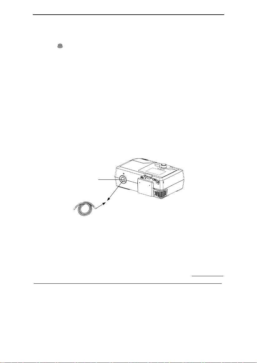
11.4 Assembling the Tube and Mask
(1) Connect one end of the tube to the air outlet of the device, as shown in Fig. 11-4.
Fig. 11-4
(2) Connect the other end of the tube to the mask according to the user manual for the mask.
Wear the mask.
WARNINGS!
• If multiple persons are going to use the device (e.g., rental devices), a low-resistance, main
flow bacteria filter should be installed in-line between the device and tube. Pressures must
be verified by your home care provider when alternate or optional accessories are in place.
• If you are using a mask with a built-in exhalation port, connect the mask’s connector to the
tube.
• If you are using a mask with a separate exhalation port, connect the tube to the exhalation
port. Position the exhalation port so that the vented air is blowing away from your face.
Connect the mask’s connector to the exhalation port.
• If you are using a full-face mask (a mask covering both your mouth and nose), the mask
13 / 39
Page 17

G2S A20 / G2S C20 User Manual V1.0
must be equipped with a safety (entrainment) valve.
• In order to minimize the risk of CO2 rebreathing, the patient should observe the following
instructions:
- Use the accompanying tube and mask provided by BMC.
- Do not wear the mask for more than a few minutes while the device is not operating.
- Use only masks with vent holes. Do not block or try to seal the vent holes in the exhalation
port.
CAUTION!
• When using the tube with a diameter of 15mm, set the tube of the Patient Menu to 15mm
(see Section 14.2 “Options of the Patient Menu and Corresponding Descriptions”).
11.5 Using Oxygen with the Device
Oxygen may be added at the mask connection. Please observe the instructions listed below
when using oxygen with the device.
WARNINGS!
• Connect the oxygen tube to the oxygen inlet of the mask.
• The oxygen supply must comply with the local regulations for medical oxygen.
• Turn on the device before turning on the oxygen. Turn off the oxygen before turning off the
device. Explanation of Warning: When the device is turned off, but the oxygen flow still exists,
oxygen may accumulate within the device's enclosure and pose a fire hazard. Turning off the
oxygen before turning off the device will prevent oxygen accumulation in the device and
reduce the risk of fire. This warning applies to CPAP devices.
• Oxygen supports combustion. Keep the device and the oxygen container away from heat,
open flames, any oily substances, or other sources of ignition. DO NOT smoke in the area
near G2S A20 / G2S C20 or the oxygen container.
• Sources of oxygen should be located more than 1 m from the device.
• When using oxygen with this system, a Pressure Valve must be placed in-line with the
patient circuit between the device and the oxygen source. The pressure valve helps prevent
the backflow of oxygen from the patient circuit into the device when the unit is off. Failure to
use the pressure valve could result in a fire hazard.
• Do not connect the device to an unregulated or high pressure oxygen source. The pressure
of oxygen source does not exceed the work pressure of the device.
14 / 39
Page 18
G2S A20 / G2S C20 User Manual V1.0
SD Card Slot
11.6 Inserting the SD Card (Only for the device that
equipped with SD card)
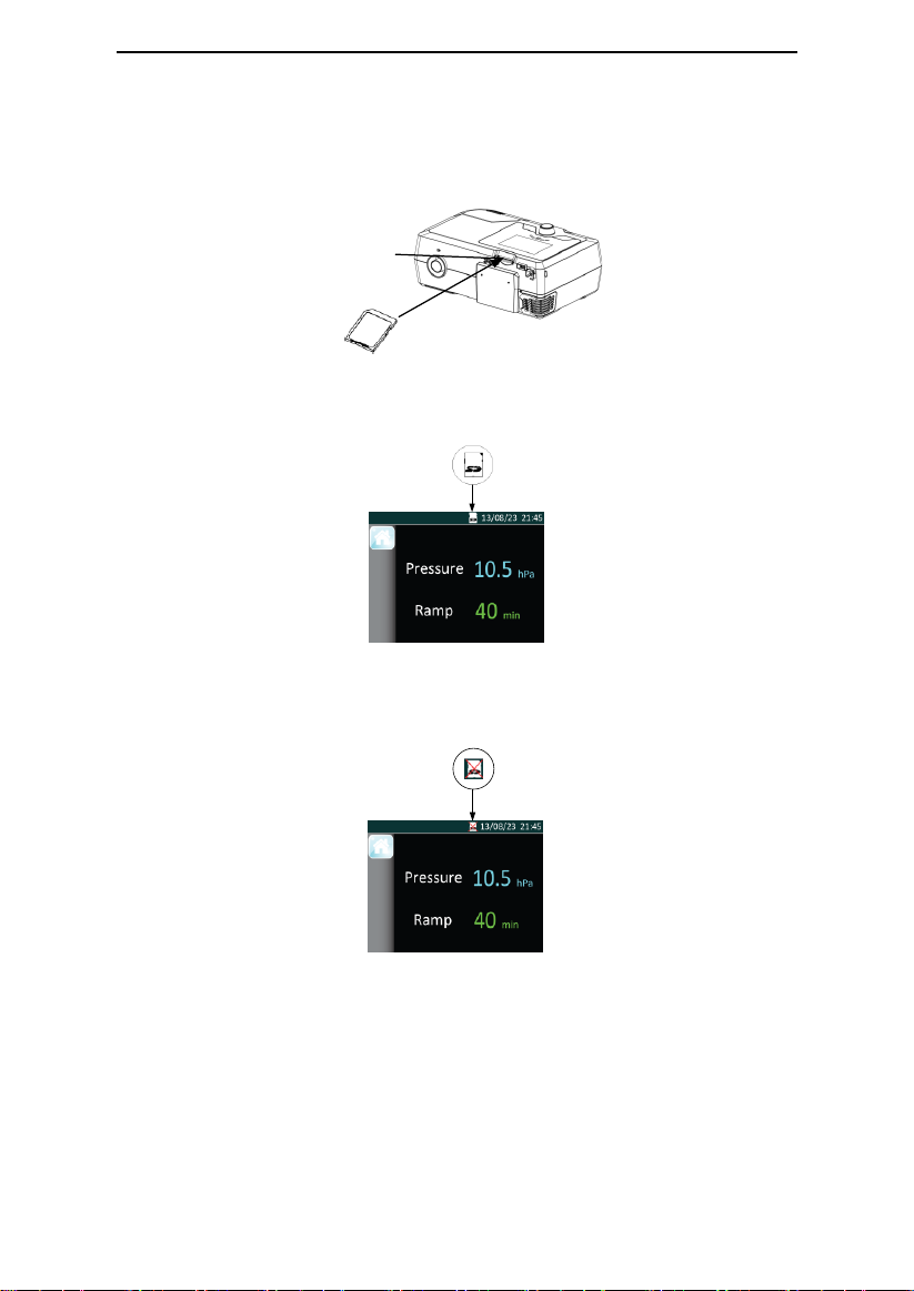
Insert the SD card into the SD Card Slot, as shown in Fig. 11-5.
Fig. 11-5
If the SD card is inserted correctly, a symbol indicating correct insertion will appear in the
Main Interface on the screen of the device, as shown in Fig. 11-6.
Fig. 11-6
If the SD card is inserted incorrectly, a symbol indicating incorrect insertion will appear in the
Main Interface on the screen of the device, as shown in Fig. 11-7.
Fig. 11-7
CAUTIONS!
• If the SD card is not inserted, there will not be a symbol appear in the Main Interface on the
screen of the device.
• To avoid data loss or any damage to the SD card, the SD card can only be removed after the
device stops delivering air.
15 / 39
Page 19

G2S A20 / G2S C20 User Manual V1.0
11.7 Using the Cellular Module
For more details, please refer to the corresponding user manual.
11.8 Starting Treatment
Connect the device to a power outlet, press the Knob , and the device will start
delivering air.
WARNINGS!
• Be sure to follow your physician’s instructions on adjusting the settings! To order any
accessories not included with this device, contact your equipment supplier.
• DO NOT connect any ancillary equipment to this device unless recommended by BMC or
your physician. If you suffer from chest discomfort, shortness of breath, stomach bloating, or
severe headache when using the device, contract your physician or qualified medical
personnel immediately.
12. Routine Use
12.1 Connecting the Tube
Connect the power cord, power adapter, and tube properly according to the instructions in
the First Time Setup (Chapter 11). Connect the mask and headgear according to the user
manual for the mask.
CAUTION!
• Before each use, examine the tube for any damage or debris. If necessary, clean the tube
to remove the debris. Replace any damaged tube. Make sure that the mask does not leak.
12.2 Adjusting the Tube
Lie down on your bed, and adjust the tube so it is free to move if you turn during sleep.
Adjust the mask and headgear until you have a comfortable fit and until there are no airflow
leaks around the mask.
12.3 Turning on the Airflow
Press the Knob to turn on the airflow. The screen will display treatment pressure and
other information.
12.4 Heating the Water
Pay attention to the humidifier indicator lights when using the humidifier. The indicator lights
indicate the On / Off state of the humidifier. It is off when all indicator lights go out.
CAUTION!
• Observe the water level of the water chamber before using the humidifier. Make sure there
is sufficient water in the water chamber, and avoid heating the device with an empty water
chamber.
16 / 39
Page 20
G2S A20 / G2S C20 User Manual V1.0
12.5 Using the Ramp Button
Every time the Ramp Button is pressed, the pressure will drop to the initial pressure,
and then gradually rise to the prescribed treatment pressure according to the preset ramp
time, so as to make the patient fall asleep easily. The screen displays a real-time countdown
of the remaining ramp time in minutes.
CAUTIONS!
• You can press the Ramp Button as often as you wish during sleep.
• The ramp feature is not prescribed for all users.
12.6 Turning the Device Off
Take off the mask and headgear, press and hold the Knob for two seconds, and the
device will stop delivering air. Disconnect the power cord from the power outlet to power off
the device.
CAUTION!
• Do not position the device where it is difficult to disconnect the device.
13. Heated Humidifier
The humidifier is available from your home care provider. The humidifier may reduce nasal
dryness and irritation by adding moisture (and heat if applicable) to the airflow.
13.1 Filling the Water Chamber
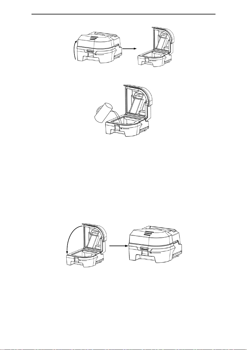
13.1.1 Removing the Water Chamber
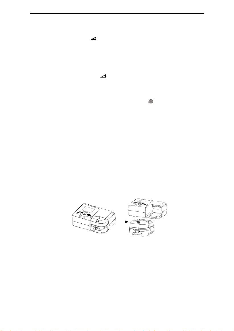
Grab the water chamber, and pull it out of the device, as shown in the figure below.
Fig. 13-1
WARNING!
• Turn the device off and allow approximately 15 minutes for the heater plate and water to
cool.
13.1.2 Filling Water
Open the cap, as shown in Fig. 13-2, and fill the water chamber with approximately 360 ml
of water, as shown in Fig. 13-3. Make sure that the water does not exceed the maximum
water level line.
17 / 39
Page 21
G2S A20 / G2S C20 User Manual V1.0
Fig. 13-2
Fig. 13-3
WARNING!
• Change water before every use and do not surpass the MAX fill line.
CAUTIONS!
• Empty the water chamber when the heated humidifier is not in use.
• Distilled water is recommended.
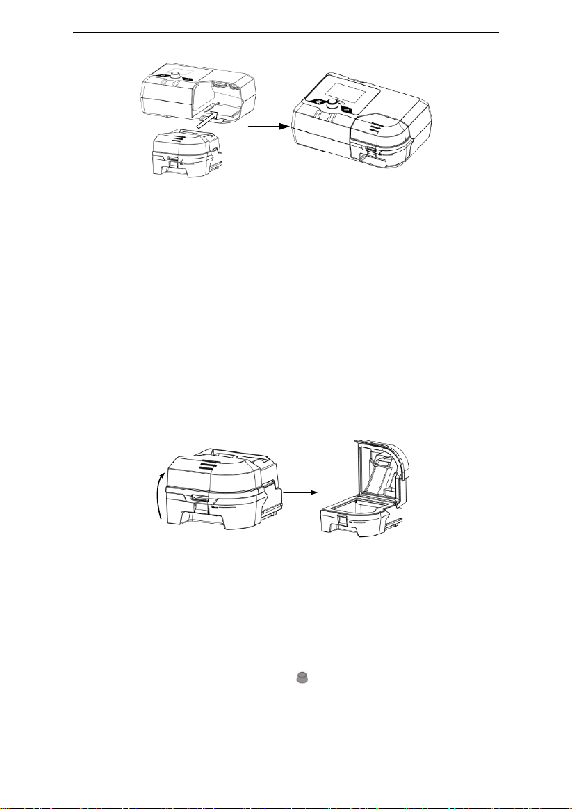
13.1.3 Inserting the Water Chamber
Close the cap after it is filled with water, as shown in Fig. 13-4, and return it to the device, as
shown in Fig. 13-5.
Fig. 13-4
18 / 39
Page 22
G2S A20 / G2S C20 User Manual V1.0
Fig. 13-5
WARNING!
• For safety purposes, the device must be placed on a flat surface at a level lower than the
patient's head on a bed, so that the condensation flows back to the water chamber rather
than remain in the tubing causing rainout.
CAUTIONS!
• Avoid moving or tilting the device when the water chamber has water in it.
• Take precautions to protect furniture from water damage.
13.2 Emptying the Water Chamber
(1) Removing the water chamber according to instructions in 13.1.1.
(2) Emptying the water chamber: Open the cap, as shown below, and pour any
remaining water out of the water chamber.
Fig. 13-6
CAUTION!
• Empty and air-dry the water chamber when the device is not in use.
(3) Inserting the Water Chamber according to instructions in 13.1.3.
13.3 Setting the Humidity Level
After the device is powered on, turn the Knob to turn on or turn off the heated
humidifier and to adjust the humidity level according to instructions on the screen of the
device.
19 / 39
Page 23
G2S A20 / G2S C20 User Manual V1.0
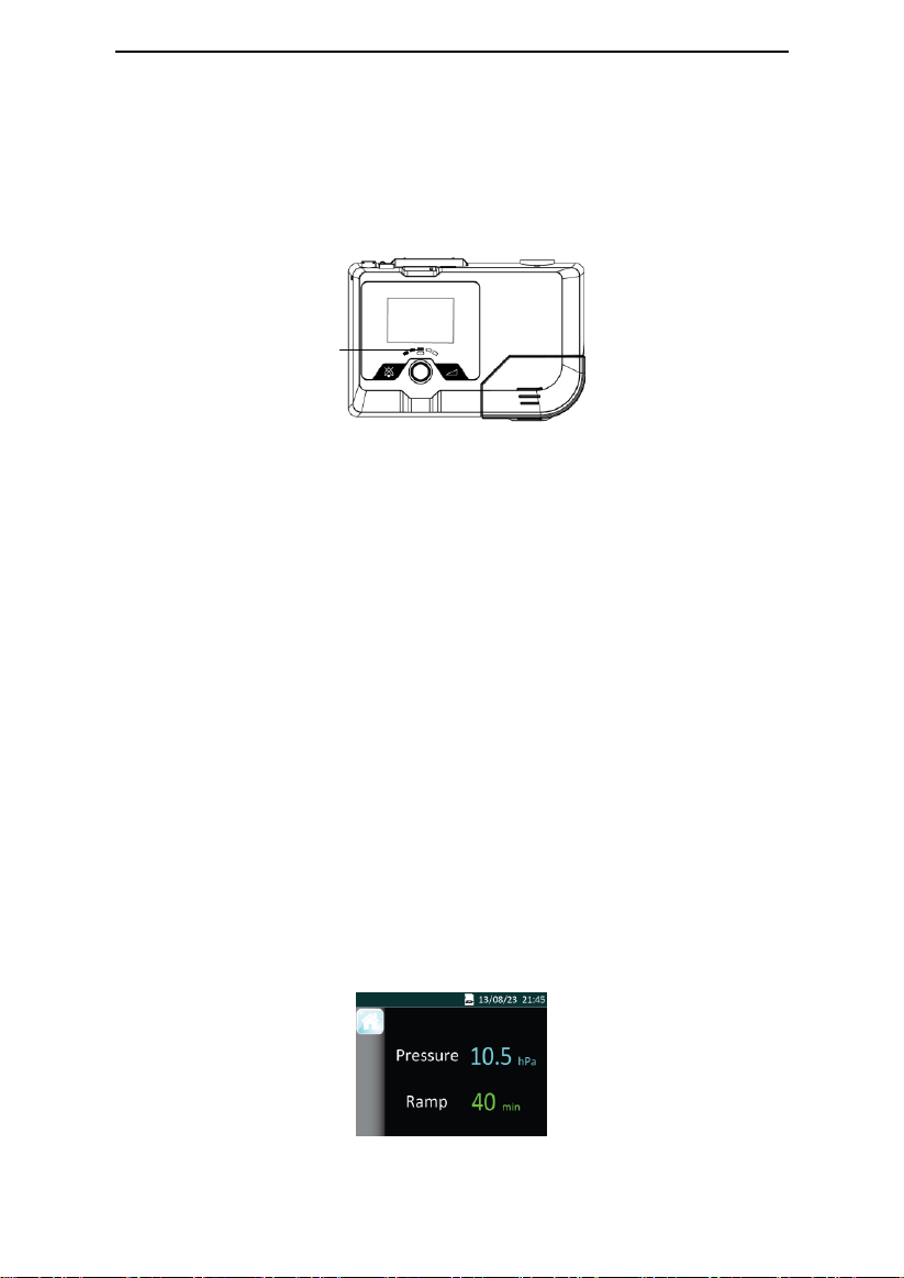
Humidifier Indicator
There are five humidity levels available, and the number of blue indicator lights that light up
is directly proportional to the humidity level. If none of the indicator lights light up, it means
that the heated humidifier is turned off.
The temperature of the water in the water chamber maintains a constant set level. Three
indicator lights light up when the humidity is adjusted to Level 3, as shown in Fig. 13-7.
Fig. 13-7
CAUTIONS!
• Generally speaking, the humidity inside the mask is low when the water temperature is low.
• The greater the difference between the temperature inside the air tubing and room
temperature is, the more easily condensation occurs inside the tubing.
• If there are only a few condensed water droplets inside the tubing in the morning after
therapy, it means that the humidity level is appropriate; if there is lots of condensed water
droplets inside the tubing and / or mask, it means that the humidity level is too high and
should be set lower; Nasal dryness means that the humidity level is too low and should be set
higher.
WARNING!
• Do not touch the heater plate of the device when it is working, otherwise you may get
burned. Turn off the heat when the heated humidifier is not in use.
14. Navigating the Patient Menu
14.1 Steps to Navigating the Patient Menu
14.1.1 Accessing the Main Interface
Connect the power cord and power adapter properly. The screen displays the Main Interface
shown in Fig. 14-1.
Fig. 14-1
20 / 39
Page 24
G2S A20 / G2S C20 User Manual V1.0
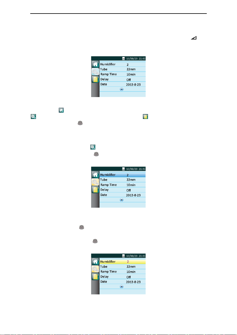
14.1.2 Bringing up the Initial Setup Interface
From the Main Interface shown in Fig. 14-1, press and hold the Ramp Button for
three seconds. The screen displays the Initial Setup Interface of the Patient Menu, as shown
in Fig. 14-2.
Fig. 14-2
The first icon on the left side of the screen indicates the Main Interface, the second icon
indicates the Initial Setup Interface, and the third icon indicates the iCode Interface.
As you turn the Knob , the cursor switches among the three icons, and the interface
displayed on the screen changes accordingly.
14.1.3 Accessing the Setup Interface
When the cursor is on the icon , the screen displays the Setup Interface. Access the Setup
Interface by pressing the Knob . The first option on the Setup Interface is then displayed
in blue, as shown in Fig. 14-3.
Fig. 14-3
14.1.4 Selecting Options
As you turn the Knob clockwise, the cursor moves downwards from one option to
another. As you turn it counterclockwise, the cursor moves upwards. When the cursor is on a
certain option, press the Knob , and the option is then displayed in yellow, meaning that
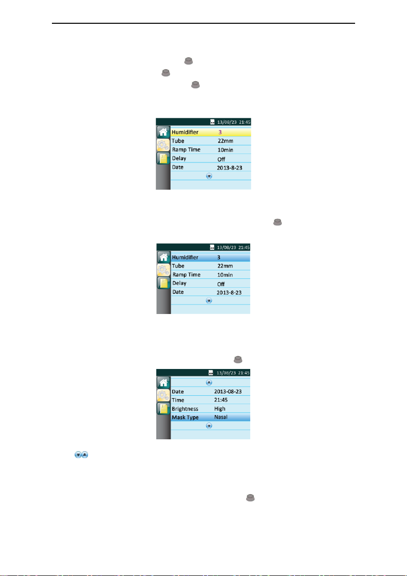
the option can now be adjusted, as shown by the Humidifier option in Fig. 14-4.
Fig. 14-4
21 / 39
Page 25
G2S A20 / G2S C20 User Manual V1.0
14.1.5 Adjusting Options
Adjust the option by turning the Knob . As shown in Fig. 14-4, the Humidifier option is
selected. As you turn the Knob clockwise, the numbering increases, indicating a higher
humidity level. As you turn the Knob counterclockwise, the numbering decreases,
indicating a lower humidity level. The Humidifier option is still displayed in yellow, as shown
in Fig. 14-5.
Fig. 14-5
14.1.6 Confirming Adjustments
Confirm your adjustment to an option by pressing the Knob . The option is then
displayed in blue, as shown in Fig. 14-6.
Fig. 14-6
14.1.7 Turning Pages
When the cursor is on Mask Type, the last option shown in Fig. 14-6, the remaining options will
appear on a new page if you continue to turn the Knob clockwise, as shown in Fig. 14-7.
Fig. 14-7
Note: are page turning symbols.
14.1.8 Exiting the Patient Menu
(1) Returning to the Initial Setup Interface
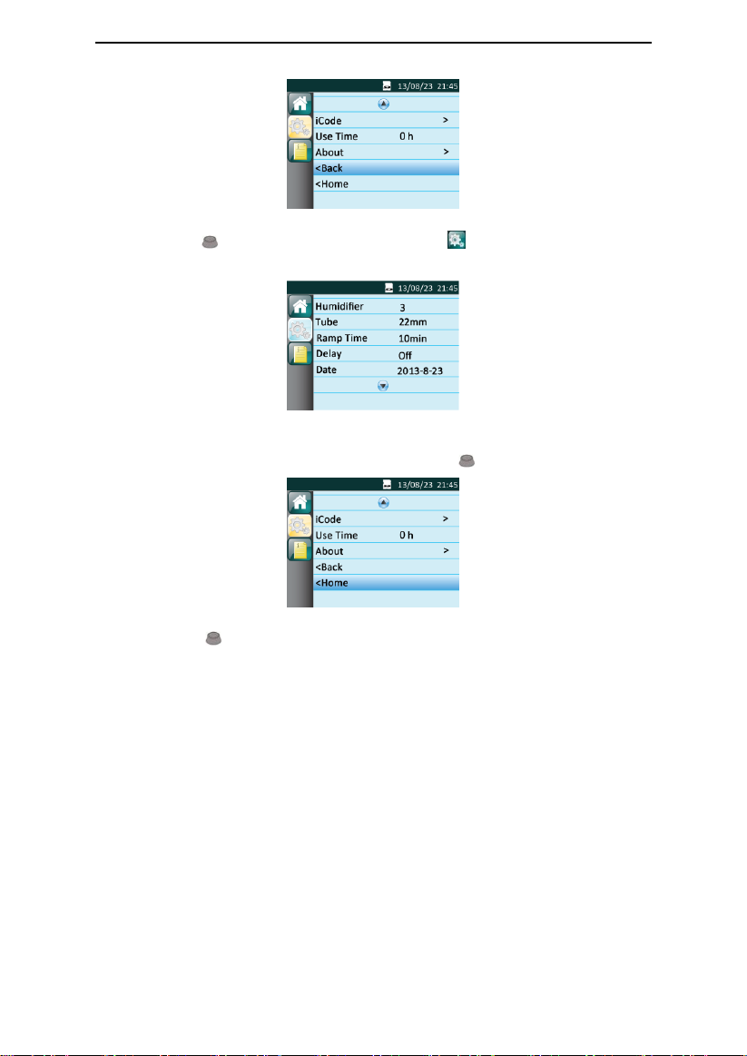
Move the cursor to the Back option by turning the Knob , as shown in Fig. 14-8.
22 / 39
Page 26
G2S A20 / G2S C20 User Manual V1.0
Fig. 14-8
Press the Knob , the cursor jumps to the second icon on the left side of the screen.
The screen displays the Initial Setup Interface, as shown in Fig. 14-9.
Fig. 14-9
(2) Returning to the Main Interface
Move the cursor to the Home option by turning the Knob , as shown in Fig. 14-10.
Fig. 14-10
Press the Knob to exit the Patient Menu. The screen will display the Main Interface
shown in Fig. 14-1.
23 / 39
Page 27
G2S A20 / G2S C20 User Manual V1.0
Option
Range
Description
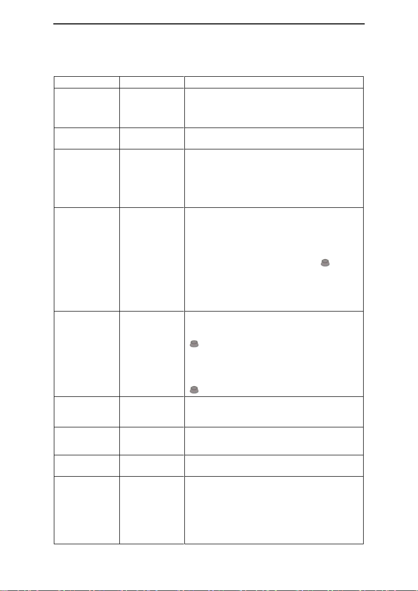
Humidifier
Off, 1 ~ 5
There are five humidity levels available. As the
numbering increases, the humidity rises
accordingly. “Off” means the humidifier is turned
off. The default setting is “2”
Tube
15mm / 22mm
Setting diameter of the tube by adjusting this
option. The default setting is “22mm”
Reslex
Off, 1 ~ 3
This feature enables the device to automatically
reduce the treatment pressure when the patient
exhales, so as to make the user more comfortable.
The higher the numbering is, the more pressure
the device reduces. “Off” means this feature is
disabled. The default setting is “Off”
Ramp Time
0 - Max Ramp
In order to increase comfort and help the patient
fall asleep easily, the pressure can increase
gradually, when the Ramp feature is enabled. The
ramp time during which the initial pressure rises to
the prescribed treatment pressure can be
adjusted. As you turn the Knob to the
nearest point, the numbering increases or
decreases by five minutes. The default setting is
“10 minutes.” The screen displays a real-time
countdown of the remaining ramp time in minutes
Delay
On / Off
When the humidifier is on, this feature allows the
airflow to continue for about 15 minutes at a low
pressure (about 2 hPa) after you press the Knob
to discontinue treatment. This will blow off the
vapor left in the water chamber to avoid any
damage to the device. When this feature is set to
“Off,” which means it is disabled, the airfolw stops
delivering air instantly after you press the Knob
. The default setting is “Off”
Date
2000-01-01
—
2099-12-31
Set date by adjusting this option
Time
00:00
—
23:59
Set time by adjusting this option
Brightness
High / Low
Setting screen brightness by adjusting this option.
The default setting is “High”
Mask Type
Full Face;
Nasal; Pillow;
Other
There are three mask types available, Full Face
(full-face mask), Nasal (nasal mask), and Pillow
(nasal pillow mask). The default mask type is
“Nasal,” but the patient can choose other suitable
masks as well. When selecting masks other than
the above three types of BMC masks, the patient
can identify the masks as other.
14.2 Options of the Patient Menu and Corresponding
Descriptions
24 / 39
Page 28
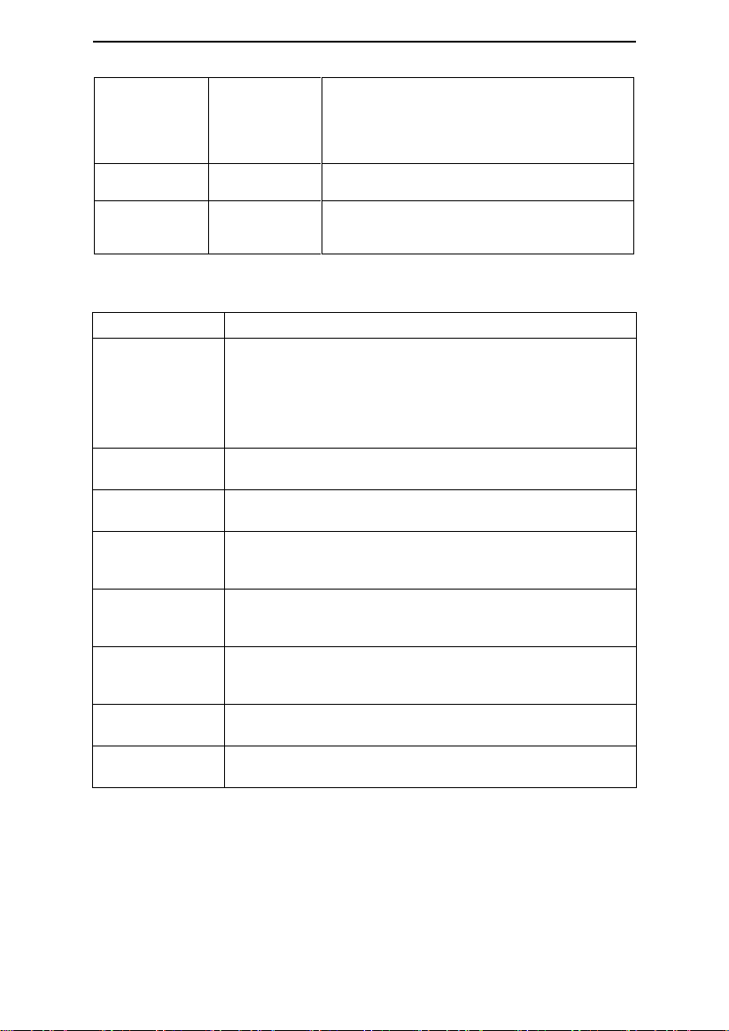
iCode
iCode,
iCode QR,
iCode QR +
iCode provides access to the patient's compliance
data during a recent time period. The iCode mode
displays data in sequences of numbers, and the
iCode QR / iCode QR + mode displays data in
two-dimensional codes
Use Time
0 ~ 50000 h
Use Time displays how long has the device been
used by the patient. The use time can be erased
About
——
Displays related information of the device (Model,
SN, Version, ID). This is read-only and cannot be
edited
15. Alert
Alert Message
Description
Power Failure!!!
An audible alert will sound in 6 s if the device is accidentally
disconnected from power when it is delivering air.
Note:
(1) The alert will not sound if power failure occurs when the device
is in standby state.
(2) No alert message on the screen during a power failure
Device Fault!!!
An audible alert will sound if no airflow comes out of the machine;
the screen will display “Device Fault!!!”
Leak!!
When the airflow is on, an audible alert will sound in 40 s if the air
leak rate is excessive; the screen will display “Leak!!”
Low Input
Voltage!!
If the voltage supplied by power adaptor is lower than 22V, an
audible alert will sound and the screen will display “Low Input
Voltage!!”
Humidifier Failure!!
When humidifier is applied, an audible alert will sound when the
humidifier fails to work; the screen will display “Humidifier
Failure!!”
Please Change
Filter!
When the Filter Alert feature is enabled, an audible alert will sound
if the preset replacement time reaches but without replacing the air
filter; the screen will display “Please Change Filter!”
SD Card Full!
The screen will display “SD Card Full!” if the SD card has reached
its maximum capacity
Reinsert SD card!
The screen will display “Reinsert SD card!” if the SD card fails to
work
G2S A20 / G2S C20 User Manual V1.0
25 / 39
Page 29

G2S A20 / G2S C20 User Manual V1.0
16. Cleaning and Disinfection
WARNINGS!
• Regular cleaning of the device and its accessories is very important for the prevention of
respiratory infections.
• To avoid electric shock, always unplug the device before cleaning.
• Use mild soap that is nontoxic to humans.
• Follow the manufacturer's instructions on cleaning the mask and tube and on determining
the frequency of cleaning.
• Before cleaning, check whether the device has been disconnected from the power supply,
whether the power cord has been unplugged, and whether the water chamber of the device
has cooled down. Make sure the plate has cooled down to room temperature, so you do not
get burned.
• Do not open or modify the device. There are no user serviceable parts inside. Repairs and
servicing should only be performed by an authorized service agent.
CAUTIONS!
• Overheating of the materials could lead to early fatigue of these materials.
• Do not use solutions containing chlorinated lime, chlorine, or aromatic to clean the device
and its accessories. Liquid soap containing moisturizing agents or antimicrobials should not
be used either. These solutions may harden cleaned materials or reduce their lifespan.
• Do not clean or dry the device and its accessories when the temperature is higher than
80°C (176°F). High temperatures could reduce product life.
• Do not immerse the device in any fluids.
16.1 Cleaning the Mask and Headgear
For details, refer to the cleaning instructions in the user manual for the mask.
16.2 Cleaning the Cellular Module
Wipe the surface of the Cellular Module with a clean, soft, and slightly damp cloth.
CAUTION!
• It is recommended to clean the Cellular Module once a week.
16.3 Cleaning the Water Chamber
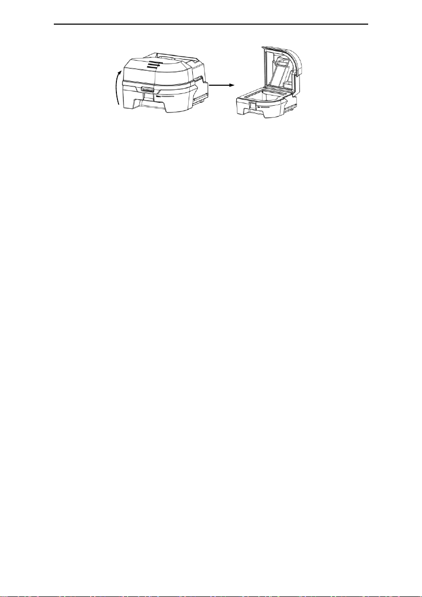
(1) Opening the Water Chamber: Open the cap of the water chamber, as shown in Fig.
16-1.
26 / 39
Page 30
G2S A20 / G2S C20 User Manual V1.0
Fig. 16-1
(2) Cleaning the Water Chamber: You may also clean the water chamber with a soft cloth
which does not scratch the water chamber (dip the soft cloth in liquid soap if necessary),
rinse it thoroughly, and then wipe it dry with a soft cloth.
(3) Returning the Water Chamber according to instructions in 13.1.3.
WARNINGS!
• Emptying and cleaning the water chamber daily will help prevent mold and bacteria
growth.
• Allow the water in the chamber to cool down to room temperature before removing it from
the device.
CAUTIONS!
• Clean the water chamber only after the water in it cools. Make sure that no water enters
the device.
• After cleaning, rinse the water chamber throughly in clean water to make sure that no soap
residue is left; then wipe it dry with a lint-free cloth, so as to prevent calcareous
accumulations.
• Inspect the water chamber for any leak or damage. Replace the water chamber if any
damage is present.
• It is recommended to do daily cleaning of the water chamber.
16.4 Cleaning the Enclosure
Wipe the surface of the device with a soft, slightly damp cloth.
CAUTIONS!
• The device can only be used after the enclosure is dry, so that no moisture enters the
device.
• It is recommended to clean the enclosure once a week.
16.5 Cleaning the Tube
(1) Remove the tube from the device and mask before cleaning.
(2) Clean the tube in warm water which contains washing liquid, and then rinse it in clean
water thoroughly.
27 / 39
Page 31

G2S A20 / G2S C20 User Manual V1.0
(3) After cleaning, air-dry the tube in a cool, well-ventilated area, and avoid direct sunlight. It
takes approximately 30 minutes to completely air-dry the tube. Check whether the tube is
completely dry before re-use.
CAUTION!
• It is recommended to clean the tube once a week.
16.6 Replacing the Air Filter
(1) Open the air filter cap to remove the air filter.
(2) Put the new air filter in the filter area, and then place the filter cap back properly.
CAUTIONS!
• To avoid material damage, do not place the spare air filter in direct sunlight, humid
environments, or temperatures below the freezing point. The air filter should be replaced
every 6 months (It may be replaced more frequently based on actual sanitary conditions).
• Operating the device with a dirty air filter may stop it from working properly and may cause
damage to the device.
16.7 Disinfection
Generally speaking, if you have strictly followed the above cleaning instructions, you do not
have to disinfect the device and / or water chamber. If the device is contaminated or used in
clinical trials, you may purchase disinfectants from a home medical equipment company to
disinfect the device.
Disinfection of the Water Chamber:
Prior to disinfection, clean the water chamber according to Section 16.3 “Cleaning the Water
Chamber”. The disinfection methods are as follows:
(1) Heat disinfection: Disinfect the water chamber by immersing it in tap water at 75°C±2°C
for 30 minutes.
(2) Use mild disinfectants.
CAUTIONS!
• Disinfectants tend to damage materials and reduce the life of components. Try to select the
appropriate disinfectant, and follow the disinfectant manufacturer's instructions and
recommendations.
• After disinfection, check the disinfected component for any signs of damage. Replace any
damaged component immediately.
WARNINGS!
• After disinfection, rinse any disinfected component in clean water thoroughly, especially
components in close contact with the patient such as the mask, headgear, and tube, so as to
prevent disinfectant residuals from damaging the skin or respiratory tract or causing allergies.
• The device shall not be serviced or maintained while in use with a patient.
• Sterilization of this device and its components other than recommended is not permitted.
28 / 39
Page 32

G2S A20 / G2S C20 User Manual V1.0
17. Traveling with the Device
CAUTIONS!
• Empty the water chamber before packing the device for your trip; in order to prevent any
remaining water from entering the device.
• Using the device at an incorrect elevation setting could result in airflow pressures higher
than the prescribed setting. Always verify the elevation setting when traveling or relocating.
• If the device is used when the atmospheric pressure is out of the stated range (See Section
5), the accuracy of the leakage alert will be affected.
(1) Use the BMC carrying case to carry the device and accessories along with you. Do not put
them in your checked baggage.
(2) This device operates on power supplies of 100 ~ 240 V and 50 / 60 Hz, and is suitable
for use in any country in the world. No special adjustment is necessary, but you will need to
find out the types of the power sockets in your destination. Bring, if necessary, a power
socket adaptor which can be purchased in electronics stores.
(3) Remember to bring a spare air filter and the emergency documents (filled and signed by
your physician) about this device. If you plan to travel by air, remember to bring the
multi-language emergency documents about respiratory therapy, in case that the border and
customs officers in your destination country inspect the device. With the emergency
documents, you can prove to them that it is a medical device.
(4) Security Stations: For convenience at security stations, there is a note on the bottom of
the device stating that it is medical equipment. It may be helpful to bring this manual along
with you to help security personnel understand the device.
29 / 39
Page 33

G2S A20 / G2S C20 User Manual V1.0
18. Transferring the Device to Another Patient
If the device is transferred to another patient, components in close contact with the previous
owner, including the mask, headgear, tube, and air filter, should be replaced to prevent
cross-infection.
19. Reordering
Contact your home care provider to order accessories or replacement filters.
The device does not require routine servicing.
WARNINGS!
• If you notice any unexplained changes in the performance of the device, if it is making
unusual or harsh sounds, if it has been dropped or mishandled, if the enclosure is broken, or
if water has entered the enclosure, discontinue use. Contact your home care provider.
• If the device malfunctions, contact your home care provider immediately. Never attempt to
open the enclosure of the device. Repairs and adjustments must be performed by BMC
-authorized service personnel only. Unauthorized service could cause injury, invalidate the
warranty, or result in costly damage.
• If necessary, contact your local authorized dealer or BMC Medical Co., Ltd., for technical
support and documents.
20. Technical Support
Please contact BMC directly if you need the circuit diagram of the device and the list of
components for certain purposes such as maintenance or connection to other equipment.
BMC will provide the circuit diagram and / or other technical documents in whole or in part
according to your needs.
21. Disposal
When the device reaches the end of its service life, dispose of the device and packaging in
accordance with local laws and regulations.
30 / 39
Page 34
G2S A20 / G2S C20 User Manual V1.0
Problem
Possible Cause
Solution(s)
Dry, cold, runny,
and blocked
nose; having a
cold
The nose reacts to the airflow
and cold. Due to fast airflow,
the air becomes cold, leading
to nasal mucosa irritation and
subsequent dryness and
swelling
Increase the humidity setting of
the device.
Contact your physician, and
continue treatment unless the
physician suggests the opposite
Dry mouth and
throat
Probably because the patient
sleeps with his or her mouth
open, and the pressurized air
goes out via the mouth,
leading to nasal and throat
dryness
Use a chin strap to prevent the
mouth from opening during sleep,
or use a full-face mask. Contact
your physician for details
Eye irritation
The mask size or model may
not be correct, or the mask is
not positioned correctly,
thereby leading to air leakage
Narrow the distance between the
forehead support of the mask and
the forehead. Note that adjusting
the mask too tight may leave
markings on the patient’s face.
Add additional filling to the mask
so it does not leak.
Contact your equipment supplier
for an appropriate mask. Add
additional filling to the mask if
necessary
Mask cushion (the soft part of
the mask) hardens
Replace the mask or mask cushion
Facial reddening
The mask is too tight
Loosen the headgear
The distance between the
forehead support of the mask
and the forehead is not
correct
Try a different distance. The angle
and size of the forehead support
differ according to the type of
masks
Wrong mask size
Contract your equipment supplier
for a correct-size mask
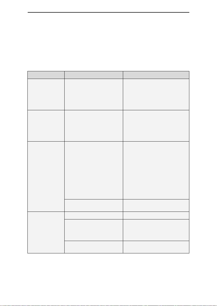
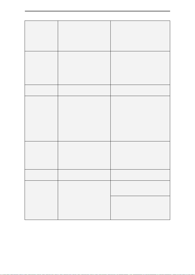
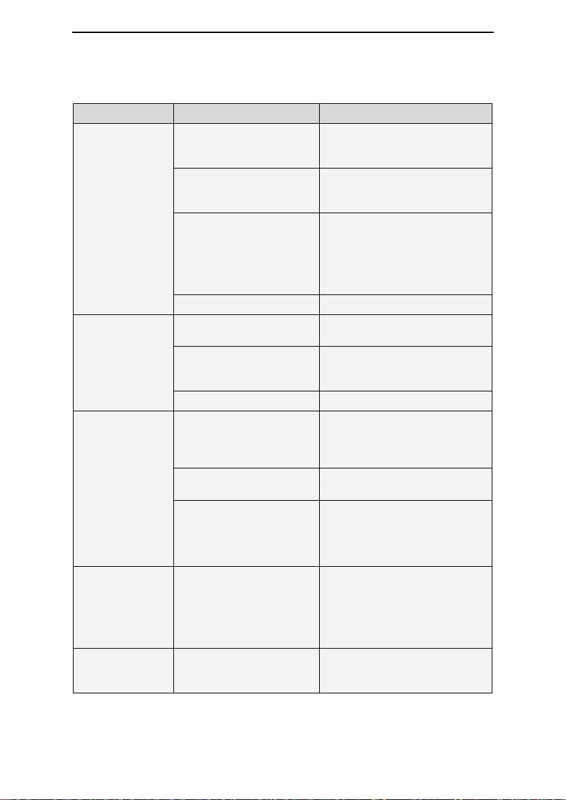
22. Troubleshooting
The table below lists common problems you may have with the device and possible solutions
to those problems. If none of the corrective actions solve the problem, contact your home
care provider.
22.1 Common Problems in Patients and Corresponding
Solutions
31 / 39
Page 35
G2S A20 / G2S C20 User Manual V1.0
The patient is allergic to the
materials of the mask
Contact your physician and
equipment supplier.
Use a mask which is not made with
natural rubber latex.
Place a lining between the skin and
mask
Water in mask
When the humidifier is used,
the humidified air tends to
condense in the cold tube and
mask if the room temperature
is low
Turn the humidity setting down, or
raise the room temperature.
Place the tube under the quilt, or
use the tube cover.
Hang the tube loosely, and the
lowest part of the tube should be
lower than the patient's head
Nasal, sinus, or
ear pain
Sinus or middle ear
inflammation
Contact your physician
immediately
Discomfort due to
inability to adapt
to the treatment
pressure
The patient will feel
uncomfortable when the
treatment pressure is higher
than 13 hPa. However, the
treatment pressure is
determined according to the
patient's conditions, and
cannot treat sleep apnea if the
treatment pressure is set too
low
It takes a maximum of four weeks
to adapt to pressurized air.
Relax and breathe through the
nose. If the problem still exists,
contact your physician
Obstructive sleep
apnea symptoms
recur
Probably because the patient
sleeps with his or her mouth
open, and the pressurized air
goes out via the mouth,
leading to blockage in the
respiratory tract
Use a chin strap to prevent the
mouth from opening during sleep,
or use a full-face mask. Contact
your physician for details
The device is too
noisy
The tube is not connected
properly
Reconnect the tube properly
Air delivered from
the device is
abnormally hot
The air inlet of the device may
be partially blocked, leading to
insufficient airflow into the
device
Replace the air filter (see 15.6
Replacing the Air Filter), and clean
the air inlet
Place the device in an area where
air flows freely, and make sure the
device is at least 20 centimeters
away from the wall, curtain, or
other things
32 / 39
Page 36
G2S A20 / G2S C20 User Manual V1.0
Problem
Possible Cause
Solution(s)
The device does
not work when it is
turned on
The Auto On / Off feature is
enabled
Take a few deep breaths with the
mask on, and the device will start
automatically
Power is not connected
properly
Ensure that the power cord, power
adapter, and the device are
connected properly
There is no voltage
Check whether a power outage
occurs by turning on a light or
other means. If you are sure the
fuse in the device is broken,
contact your equipment supplier
for repair
Cannot find any cause
Contact your equipment supplier
The device is
working, but the
pressure inside the
mask differs from
the set treatment
pressure
The tube is not connected
properly
Reconnect the tube properly
There may be holes in the
mask or pressure sensing
tube
Contact your equipment supplier
It is a faulty device
Contact your equipment supplier
The device
produces very low
pressures
The air inlet of the device
may be blocked
Replace the air filter (see 16.6
Replacing the Air Filter), and clean
the air inlet. Make sure the air inlet
is unblocked
The treatment pressure has
been changed accidentally
Contact your physician
When the Ramp feature is
enabled, it takes some time
for the initial pressure to rise
to the treatment pressure.
This is normal
If necessary, disable the Ramp
feature, or set the ramp time
shorter
After the device is
turned on, the
screen displays
intermittently, or
displays nothing at
all
The operating system of the
device needs to be
readjusted or restarted
Unplug the power cord of the
device, and re-plug it 20 seconds
later
The device is in
standby, and will
not start
The operating system of the
device needs to be
readjusted or restarted
Unplug the power cord of the
device, and re-plug it 20 seconds
later
22.2 Common Problems in the Device and Corresponding
Solutions
33 / 39
Page 37
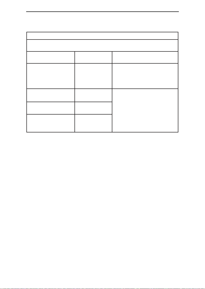
G2S A20 / G2S C20 User Manual V1.0
Guidance and manufacturer's declaration - electromagnetic emissions
The device is intended for use in the electromagnetic environment specified below. The
user of the device should ensure that it is used in such an environment.
Emissions Test
Compliance
Electromagnetic Environment Guidance
RF emissions
CISPR 11
Group 1
The device uses RF energy only for
its internal function. Therefore its RF
emissions are very low and are not
likely to cause any interference in
nearby electronic equipment
RF emissions
CISPR 11
Class B
The device is suitable for use in all
establishments including domestic
establishments and those directly
connected to the public low-voltage
power supply network that supplies
buildings used for domestic purposes
Harmonic emissions
IEC 61000-3-2
Class A
Voltage fluctuations
/ flicker emissions
IEC 61000-3-3
Complies
23. EMC Requirements
34 / 39
Page 38
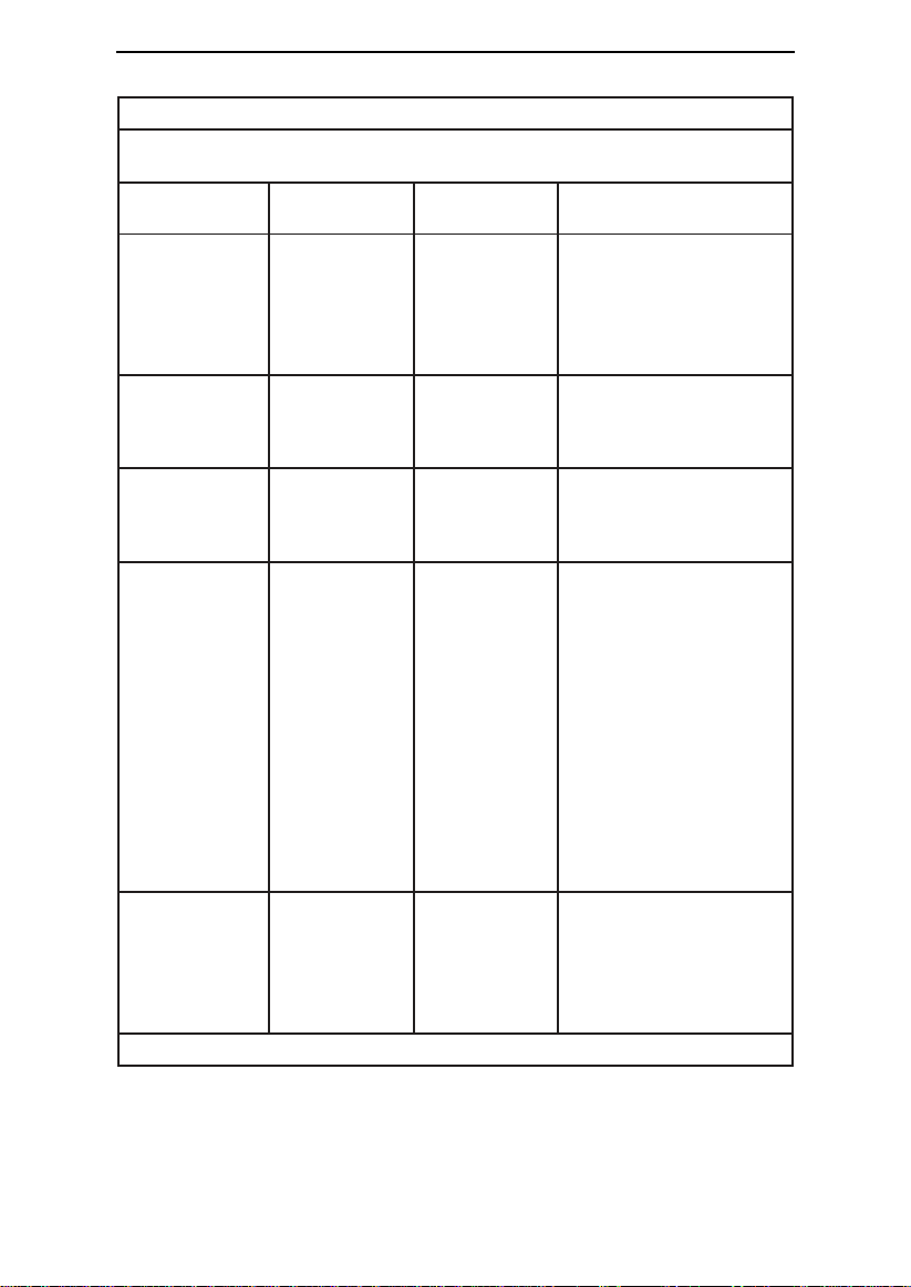
G2S A20 / G2S C20 User Manual V1.0
Guidance and manufacturer's declaration - electromagnetic immunity
The device is intended for use in the electromagnetic environment specified below. The
user of the device should make sure that it is used in such an environment.
Immunity Test
IEC 60601
Test Level
Compliance
Level
Electromagnetic
Environment - Guidance
Electrostatic
discharge (ESD)
IEC 61000-4-2
± 8 kV contact
± 15 kV air
± 8 kV contact
± 15 kV air
Floor should be wood,
concrete or ceramic tile. If
floors are covered with
synthetic material, the
relative humidity should be
at least 30%
Electrical fast
transient / burst
IEC 61000-4-4
± 2 kV for
power supply
lines
± 2 kV for
power supply
lines
Mains power quality should
be that of a typical
commercial or hospital
environment
Surge
IEC 61000-4-5
± 1 kV
line(s) to line(s)
± 1 kV
line(s) to line(s)
Mains power quality should
be that of a typical
commercial or hospital
environment
Voltage dips,
short
interruptions and
voltage
variations on
power supply
input lines
IEC 61000-4-11
0%
U
T
; 0.5 cycle
At 0°, 45°, 90°,
135°, 180°,
225°, 270° and
315°
0%
U
T
; 1 cycle
70%
U
T
; 25 / 30
cycle
At 0°
0%
U
T
; 250 /
300 cycle
0%
U
T
; 0.5 cycle
At 0°, 45°, 90°,
135°, 180°,
225°, 270° and
315°
0%
U
T
; 1 cycle
70%
U
T
; 25 / 30
cycle
At 0°
0%
U
T
; 250 /
300 cycle
Mains power quality should
be that of a typical
commercial or hospital
environment. If the user of
the device requires
continued operation during
power mains interruptions, it
is recommended that the
device be powered from an
uninterruptible power supply
or a battery
Power frequency
(50 / 60 Hz)
magnetic field
IEC 61000-4-8
30 A/m
30 A/m
Power frequency magnetic
fields should be at levels
characteristic of a typical
location in a typical
commercial or hospital
environment
Note:
UT
is the AC mains voltage prior to application of the test level.
35 / 39
Page 39
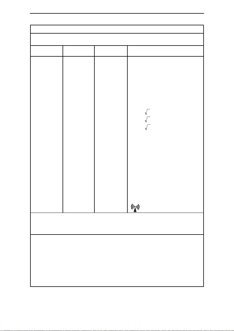
G2S A20 / G2S C20 User Manual V1.0
Guidance and manufacturer's declaration - electromagnetic immunity
The device is intended for use in the electromagnetic environment specified below. The
user of the device should make sure that it is used in such an environment.
Immunity
Test
IEC 60601
Test Level
Compliance
Level
Electromagnetic Environment Guidance
Conducted RF
IEC
61000-4-6
Radiated RF
IEC
61000-4-3
3 V
0.15 MHz ~
80 MHz
6 V in ISM
and amateur
radio bands
between
0.15 MHz
and 80 MHz
10 V/m
80 MHz to
2.7 GHz
3 V
0.15 MHz ~
80 MHz
6 V in ISM and
amateur radio
bands
between
0.15 MHz and
80 MHz
10 V/m
80 MHz to 2.7
GHz
Portable and mobile RF
communications equipment should
be used no closer to any part of the
device, including cables, than the
recommended separation distance
calculated from the equation
applicable to the frequency of the
transmitter.
Recommended separation
distance
pd 17.1
pd 35.0
80 MHz to 800 MHz
pd 70.0
800 MHz to 2.5 GHz
Where P is the maximum output
power rating of the transmitter in
watts (W) according to the
transmitter manufacturer and d is the
recommended separation distance in
meters (m).
Field strengths from fixed RF
transmitter, as determined by an
electromagnetic site survey, a should
be less than the compliance level in
each frequency range. b
Interference may occur in the vicinity
of equipment marked with the
following symbol:
Note 1: At 80 MHz and 800 MHz, the higher frequency range applied.
Note 2: These guidelines may not apply in all situations. Electromagnetic propagation is
affected by absorption and reflection from structures, objects and people.
a
Field strengths from fixed transmitters, such as base stations for radio (cellular /
cordless) telephones and land mobile radios, amateur radio, AM and FM radio broadcast
and TV broadcast cannot be predicted theoretically with accuracy. To assess the
electromagnetic environment due to fixed RF transmitters, an electromagnetic site survey
should be considered. If the measured field strength in the location in which the device is
used exceeds the applicable RF compliance level above, the device should be observed to
verify normal operation. If abnormal performance is observed, additional measures may
be necessary, such as re-orienting or relocating the device.
b
Over the frequency range 150 kHz to 80 MHz, the field strengths should be less than 10
V/m.
36 / 39
Page 40
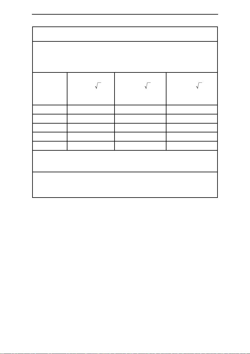
G2S A20 / G2S C20 User Manual V1.0
Recommended separation distances between portable and mobile RF
communications equipment and the device
The device is intended for use in an electromagnetic environment in which radiated RF
disturbances are controlled. The customer or the user of the device can help prevent
electromagnetic interference by maintaining a minimum distance between portable and
mobile RF communications equipment (transmitters) and the device as recommended
below, according to the maximum output power of the communications equipment.
Rated
maximum
output of
transmitter
W
150 kHz ~ 80 MHz
pd 17.1
80 MHz ~ 800 MHz
pd 35.0
800 MHz ~ 2.5 GHz
pd 70.0
0.01
0.12
0.04
0.07
0.1
0.37
0.12
0.23
1
1.17
0.35
0.70
10
3.70
1.11
2.22
100
11.7
3.50
7.00
Note 1: At 80 MHz and 800 MHz, the higher frequency range applied.
Note 2: These guidelines may not apply in all situations. Electromagnetic propagation is
affected by absorption and reflection from structures, objects and people.
For transmitters rated at a maximum output power not listed above, the recommended
separation distance d in meters (m) can be estimated using the equation applicable to the
frequency of the transmitter, where P is the maximum output power rating of the
transmitter in watts (W) according to the transmitter manufacturer.
37 / 39
Page 41
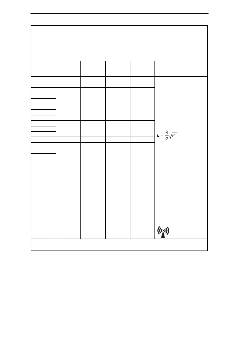
Recommended separation distances between RF wireless communications
equipment
The device is intended for use in an electromagnetic environment in which radiated RF
disturbances are controlled. The customer or the user of the device can help prevent
electromagnetic interference by maintaining a minimum distance between RF wireless
communications equipment and the device as recommended below, according to the maximum
output power of the communications equipment.
Frequency
MHz
Maximum
Power
W
Distance
IEC 60601
Test Level
Compliance
Level
Electromagnetic
Environment - Guidance
385
1.8
0.3
27
27
RF wireless communications
equipment should be used
no closer to any part of the
device, including cables,
than the recommended
separation distance
calculated from the equation
applicable to the frequency
of the transmitter.
Recommended
separation distance
Where P is the maximum
output power rating of the
transmitter in watts (W)
according to the transmitter
manufacturer and d is the
recommended separation
distance in meters (m).
Field strengths from fixed
RF transmitter, as
determined by an
electromagnetic site
survey, should be less than
the compliance level in
each frequency range.
Interference may occur in
the vicinity of equipment
marked with the following
symbol:
450 2 0.3
28
28
710
0.2
0.3 9 9
745
780
810
2
0.3
28
28
870
930
1720
2
0.3
28
28
1845
1970
2450 2 0.3
28
28
5240
0.2
0.3 9 9
5500
5785
Note 1: These guidelines may not apply in all situations. Electromagnetic propagation is affected
by absorption and reflection from structures, objects and people.
G2S A20 / G2S C20 User Manual V1.0
WARNINGS!
• This device should not be used in the vicinity or on the top of other electronic equipment
such as cell phone, transceiver or radio control products. If you have to do so, the device
should be observed to verify normal operation.
• The use of accessories and power cord other than those specified, with the exception of
cables sold by the manufacturer of the equipment or system as replacement parts for
internal components, may result in increased emissions or decreased immunity of the
equipment or system.
38 / 39
Page 42

G2S A20 / G2S C20 User Manual V1.0
24. Limited Warranty
BMC Medical Co., Ltd. warrants that the device shall be free from defects of workmanship
and materials and will perform in accordance with the product specifications for a period of
one (1) year for main unit and three (3) months for all accessories from the date of sale by
BMC Medical Co., Ltd. to the dealer. If the product fails to perform in accordance with the
product specifications, BMC Medical Co., Ltd. will repair or replace, at its option, the defective
material or part. BMC Medical Co., Ltd. will pay customary freight charges from BMC Medical
Co., Ltd. to the dealer location only. This warranty does not cover damage caused by
accident, misuse, abuse, alteration and other defects not related to material or
workmanship.
BMC MEDICAL CO., LTD. DISCLAIMS ALL LIABILITY FOR ECONOMIC LOSS, LOSS OF
PROFITS, OVERHEAD OR CONSEQUENTIAL DAMAGES WHICH MAY BE CLAIMED TO ARISE
FROM ANY SALE OR USE OF THIS PRODUCT. SOME STATES DO NOT ALLOW THE
EXCLUSION OR LIMITATION OF INCIDENTAL OR CONSEQUENTIAL DAMAGES, SO THE
ABOVE LIMITATION OR EXCLUSION MAY NOT APPLY TO YOU.
To exercise the rights under this warranty, contact the local authorized dealers or:
MANUFACTURER:
BMC Medical Co., Ltd.
Room 110 Tower A Fengyu Building, No. 115 Fucheng Road, Haidian, 100036
Beijing, PEOPLE’S REPUBLIC OF CHINA
Tel: +86-10-51663880
Fax: +86-10-51663880 Ext. 810
EU AUTHORISED REPRESENTATIVE:
Shanghai International Holding Corp. GmbH (Europe)
Eiffestraβe 80, 20537 Hamburg, Germany
Tel: 0049-40-2513175
Fax: 0049-40-255726
39 / 39
Issue date: May 18, 2018
Page 43

390920
 Loading...