

Page 1
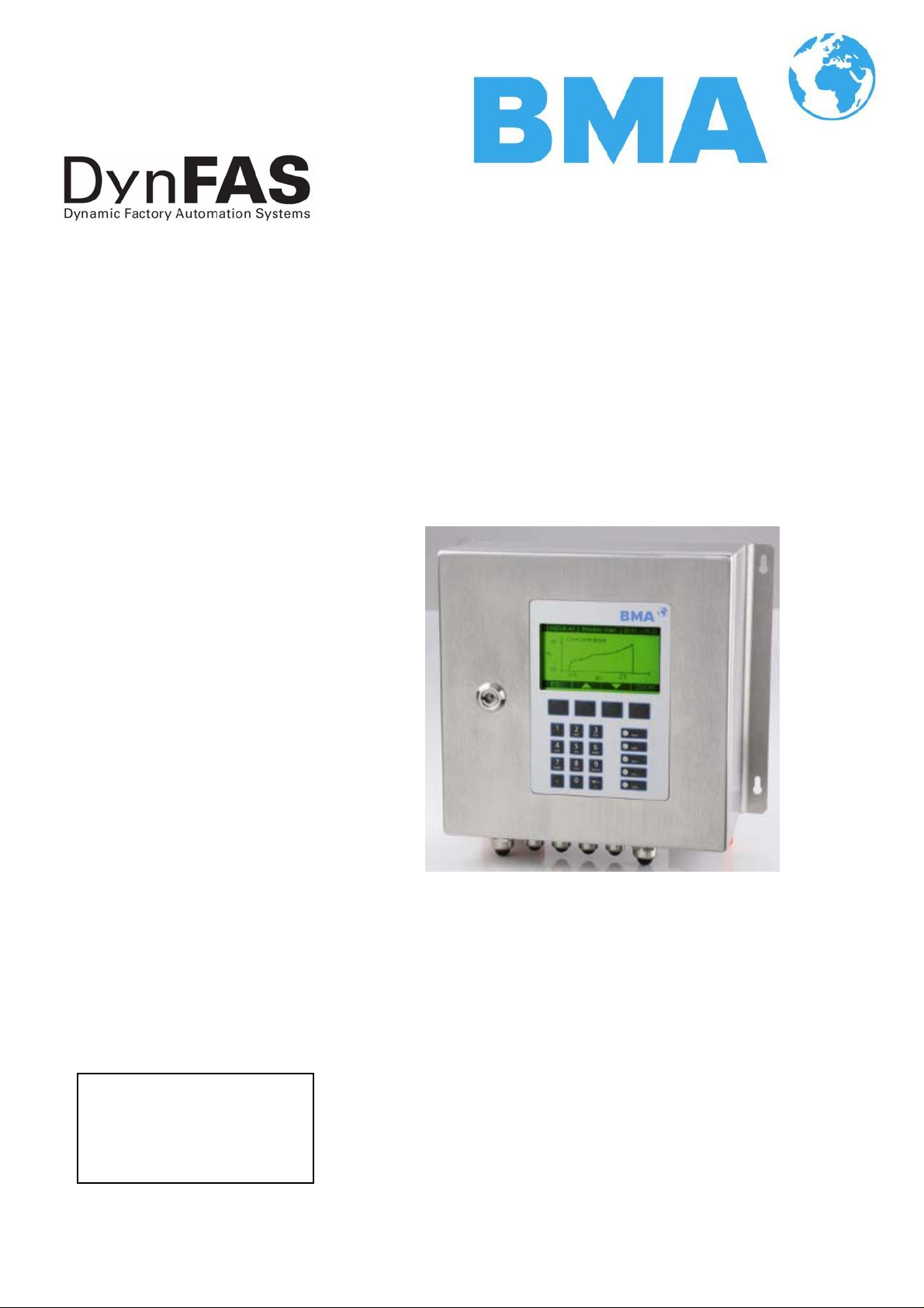
Concentration Meter
DynFAS MW
Hardware Manual
User's Guide
ID No. 54877BA2
Rev. No. 00 01.07.2009
Page 2

Page 3

Page 4

The units supplied should not be repaired by anyone other than BMA Schaltanlagen
Service engineers or technicians by BMA Schaltanlagen.
In case of operation trouble, please address to our central service department.
The complete user’s guide consists of two parts, namely the hardware and software instructions.
The hardware manual comprises:
¾ mechanical components
¾ installation
¾ electrical installation
¾ technical data
¾ electrical and mechanical drawings
The software manual comprises:
¾ operation of the control unit
¾ parameter description
¾ basic setting
¾ calibration
¾ error messages
The present part is the hardware instruction.
Subject to change without prior notice.
BMA Schaltanlagen GmbH
Am Alten Bahnhof 5 38122 Braunschweig
Germany
Tel. +49 531 804 261 ⋅ Fax +49 531 804 269
schaltanlagen@bma-de.com
www.bma-worldwide.com
DynFAS MW
Page 5

Table of Contents
Table of Contents
Page
Chapter 1. Safety Instructions 7
1.1 Identification and warning notices 7
1.2 General Instructions 8
1.3 General Safety Instructions 9
Chapter 2. General Information 11
2.1 Use and Function 11
2.2 Frequency approval 12
2.3 Intended Use 14
2.4 Definitions 15
Chapter 3. System Description 16
3.1 Principle of Measurement 16
3.2 Calculation of Measured Values 17
3.3 Temperature Compensation 18
3.4 Mechanical Components 19
3.4.1 Control Units 20
3.4.2 Flow Cell 23
3.4.3 Container Probe 24
3.4.4 High-Frequency Cable 28
3.5 Pipeline Measurement Configuration 30
3.6 Container Measurement Configuration 31
Chapter 4. Getting Started 32
4.1 Transport 32
4.2 Installation 32
4.2.1 Flow Cell Installation 32
4.2.2 Container Probe Installation 34
4.2.3 Installing the Control Unit 36
4.3 Connecting the Control Unit 37
4.3.1 Connecting the HF Cable 37
4.3.2 Pin Configuration of the Connector Strip 40
4.3.3 Digital Outputs, Relays 44
Chapter 5. Service Instructions 45
5.1 General Information 45
5.2 Wearing Parts 45
5.3 Instrument Cleaning 45
5.4 Battery 46
5.5 Fuse Replacement 46
Chapter 6. Technical Data 47
6.1 Control Unit 47
6.2 Technical Data Sensors 50
6.3 Technical Data HF-Cable 52
6.4 Format of Serial Data Output RS 232 and RS 485 53
DynFAS MW
5
Page 6

Table of Contents
Chapter 7. Certificates 55
7.1 EC Declaration of Conformity 55
7.2 Frequency Approval 57
Chapter 8. Technical Drawings 63
8.1 Dimensional Drawing of Control Unit Hous ing 63
8.1.1 Control Unit Standard CS-100 63
8.1.2 Control Unit High Dynamic CH-200 64
8.2 Electrical Wiring Diagram 65
8.3 Dimensional Drawings Flow Cells 66
8.3.1 Type FC-050-016 66
8.3.2 Type FC-065-040 67
8.3.3 Type FC-080-016 68
8.3.4 Type FC-100-016 69
8.3.5 Type FC-150-016 70
8.3.6 Type FC-020-150 71
8.3.7 Type FC-025-300 72
8.3.8 Type FC-030-150 73
8.3.9 Type FC-040-150 74
8.3.10 Type FC-060-150 75
8.4 Dimensional Drawings Probes 76
8.4.1 Type P-065-006 76
8.4.2 Type P-080-016 77
8.4.3 Type P-100-016 78
8.4.4 Type P-150-016 79
8.4.5 Type P-025-150 80
8.4.6 Type P-030-150 81
8.4.7 Installation Situation in Pipelines 82
8.5 Dimensional Drawings Flush Probes 83
8.5.1 Type PF-065-006 83
8.5.2 Type PF-080-016 84
8.5.3 Type PF-100-016 85
8.5.4 Type PF-150-016 86
8.5.5 Type PF-025-150 87
8.5.6 Installation Situation in Pipelines 88
8.6 Installation Sheets for DynFAS MW (Probe) 89
8.7 Installation Sheets for DynFAS MW (Flush Probe) 91
6
DynFAS MW
Page 7
Chapter 1 Safety Instructions
Chapter 1. Safety Instructions
1.1 Identification and warning notices
The term BMA Schaltanlagen in this User’s Manual stands for the
company BMA Schaltanlagen GmbH.
Please observe the warnings and safety instructions given in this
User’s Manual to rule out physical injury and property damage.
They are identified by the following symbols: DANGER, WARNING,
CAUTION or NOTICE.
Indicates an imminently dangerous condition. Failure to
follow the instructions will lead to death or serious injury.
Indicates a potentially dangerous condition. Failure to follow the
instructions may lead to death or serious injury.
Indicates a potentially dangerous condition. Failure to follow the
instructions may lead to slight injury or a medium-degree inju ry.
Indicates a situation which may cause property damage if the instructions are not followed.
IMPORTANT
Paragraphs with this symbol provide important information on the
product or how to work with the product.
DynFAS MW
Tip
Includes application tips and other useful information.
Further Symbols
Warning sign: no intervention, change nothing
7
Page 8

Chapter 1 Safety Instructions
Instruction: Disconnect from mains supply
Instruction: Wear safety shoes
1.2 General Instructions
The most important safety measures are summarised in this operation manual. It supplements the applicable regulations which
have to be studied by the personnel in charge.
Please keep in mind:
¾ the national safety and accident prevention regulations
¾ the national installation regulations (e.g. EN 60079)
¾ the generally accepted engineering rules
¾ the information on transportation, installation, operation, ser-
vice and maintenance
¾ the safety instructions and information in this User’s Manual
and the enclosed technical drawings and wiring diagrams
¾ the characteristic data, limit values and the information on the
operating and environmental conditions on the type labels an d
data sheets
¾ the signs on the devices
8
DynFAS MW
Page 9
Chapter 1 Safety Instructions
1.3 General Safety Instructions
IMPORTANT
The instrument housings are protected according to protection
type IP 65 and are suitable for outdoor application. The instrument has been tested by the manufacturer and is delivered in a
condition that allows safe and reliable operation.
The measuring systems have to be protected against direct sun
rays and rain during outdoor applications e. g. by a suitable protective cover.
IMPORTANT
Never change the installation and the parameter settings without
a full knowledge of these operating instruction s, as well as a full
knowledge of the behavior of the connected controller and the
possible influence on the operating process to be controlled.
Ambient conditions
The systems may be used only in technically good order and only
according to regulations!
Only authorized persons who have been trained, have the proper
qualification and have received the necessary instructions may
work with the systems! Installations and modifications on the systems which may affect the operational safety are not permitted!
IMPORTANT
All systems components require non corrosive ambient conditions
during transport, storage and starting up.
Electrical shock hazard:
Disconnect power to rule out any contact with live parts during
installation and when servicing.
Turn off power supply before opening the instrument. NEVER work
on open and live instruments.
DynFAS MW
9
Page 10
Chapter 1 Safety Instructions
Attention! Possible danger, damage to property! Concerns the system type CH-200-024 Control Unit High Dynamic 24 V DC (Id.-No.
54878-02):
When connecting the 24 V DC auxiliary power, the + and – Poles
should be connected correctly. There is no reverse voltage protection!
Qualified Persons
Spare fuses must match the rating specified by the device manufacturer. Short-circuiting or manipulation is not permitted.
IMPORTANT
The DynFAS MW and all ancillary units have to be connected to
mains via grounded connection.
IMPORTANT
The concentration measuring system DynFAS MW is to be serviced
and repaired solely by qualified persons.
Persons are qualified if they have acquired adequ ate knowledge in
the area concerned in the course of their professional education,
and if they are familiar with the pertinent national occupational
safety regulations, accident prevention regulations, directives and
acknowledged rules of technology. They must be capable of assessing the result of their work safely; moreover, they need to be
familiar with the contents of this User’s Manual.
10
IMPORTANT
If liquid gets inside the instrument, cut off the power supply. The
instrument has to be checked and cleaned by an authorized service center.
DynFAS MW
Page 11

Chapter 2 General Information
Chapter 2. General Information
2.1 Use and Function
The DynFAS MW has been designed as a concentration measuring
system and may only be used for this purpose. If it is used in any
manner, which is not described in this user’s manual, the protection of the device is impaired and all warranty claims are void.
BMA Schaltanlagen only guarantees that the devices comply with
the published specifications. The DynFAS MW may only be inst alled
in an undamaged, dry and clean condition. Alteration work and
modification of the system components are not permitted.
The DynFAS MW does not qualify as a “safety regulated measurements.
Conformance with
standards
Protection type
Misuse warning
The standards and regulations customary to the DynFAS MW are
listed in the system instructions in chapter 2.2 f requency approval
and in chapter 7.1 EC-conformity certificate.
The degree of protection of the DynFAS MW according to IEC
60529 is max. IP 65.
The following is contrary to the intended use and, therefore, has to
be prevented:
¾ Use under other conditions and prerequisites than those speci-
fied by the manufacturer in the technical documents, data
sheets, operating and installation instructions and in other specifications.
¾ Use after repair by persons who have not been authorized by
BMA Schaltanlagen.
¾ Use in a damaged or corroded state.
¾ Operation with open or inadequately closed cover.
¾ Operation with inadequately tightened adapters and screwed
cable glands.
¾ Operation without observing the safety precautions defined by
the manufacturer.
Authorized Persons
DynFAS MW
¾ Tampering with or bypassing existing saf et y in stallations.
Authorized persons are persons, who are foreseen for certain ac-
tivities as a consequence of statutory provisions, or who have been
approved by BMA Schaltanlagen for carrying out certain activities.
11
Page 12
Chapter 2 General Information
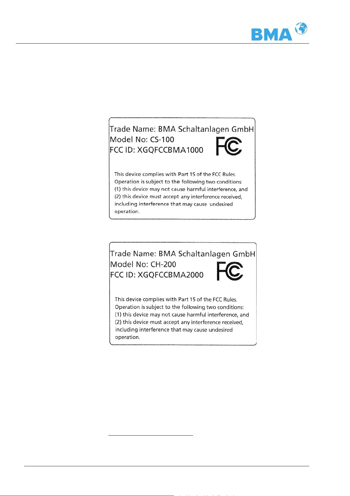
2.2 Frequency approval
The DynFAS MW complies with part 15 of the FCC1 Rules. These
devices fulfill the requirements regarding immunit y to interference
and emitted interference and are licensed for operation.
FCCApproval plates
12
1
FCC ... Federal Communications Commission
DynFAS MW
Page 13
Chapter 2 General Information
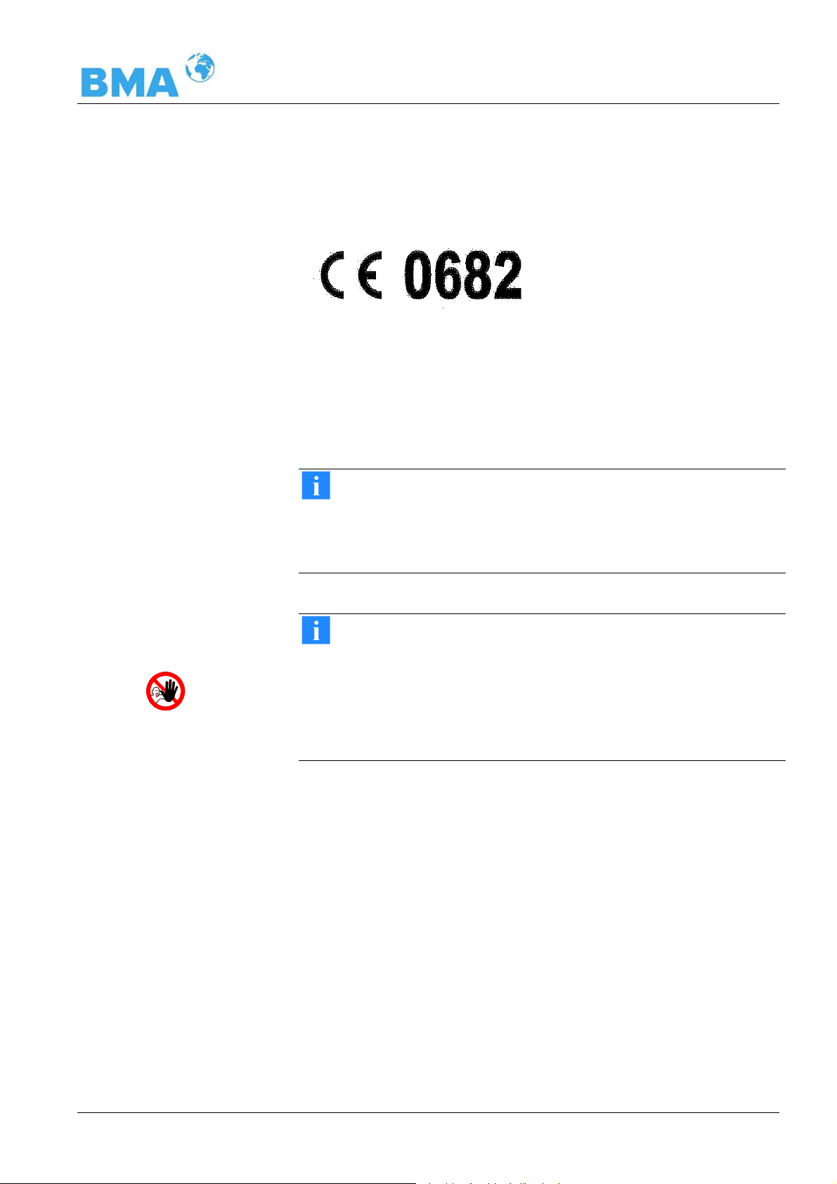
The DynFAS MW complies with the R&TTE regulations 1999/5/EG
and fulfill herein all requirements for this type of high-frequency
device. The devices bear the identification of conformity according
to the CE symbol, No. 0682 of the certification office. The certificate can be found in chapter 7.2 Frequency Approval.
The DynFAS MW is a system for concentration measurement using
microwave technology. The emitted microwaves have a very low
activity and are, therefore, not at all hazardous to human beings
or the environment. Also, the product is not affected at all by the
microwaves.
IMPORTANT
The DynFAS MW has been manufactured in compliance with the
safety requirements for microwave devices. If special legal provisions exist regarding the use of microwaves, it will be the responsibility of the user to adhere to them.
IMPORTANT
Any change in frequency or any other manipulation on the microwave device will result in a loss of the frequency approval and w ill
be prosecuted.
The microwave modules do not include any replaceable components and must not be opened.
DynFAS MW
13
Page 14

Chapter 2 General Information
2.3 Intended Use
The measuring system DynFAS MW can be used to determine the
concentration of nearly all materials which can be dissolved or suspended in water using microwave technology. The following sensor
and control unit versions are available:
1. The container probes have been designed for installation into
pipelines with a nominal width of ≥ 200 mm and in containers,
for example, crystallizers. The probe is installed such that both
measuring rods (transmitter and receiver) are immersed into
the product being measured.
2. The Flow Cell is a tubular probe, with microwave transmitter
and receiver being firmly welded onto the outside of t he pipe.
The inside of the pipe is Teflon-coated. The flow cell is installed into the existing pipeline system inline or into a bypass.
The control unit is available in two versions: The Standard Model
CS-100 and the high dynamic version CH-200. The control unit
CH-200 can only be used when sufficiently large microwave attenuation (min. 40 dB) is present. The Standard Model CS-100
should be used for lower microwave attenuation.
During operation, the concentration measuring device DynFAS MW
send out electromagnetic radiation in the frequency range between
2.4 GHz and 2.5 GHz (range restrictions depending on local regu-
lations in your country). The microwaves which emerge are not
dangerous to human beings and the environment (power emission
< 10 mW). The microwaves are emitted from the microwave window; the product is not changed by the microwaves.
To ensure proper function of the meter, please pay attention to the
following:
14
Tip
¾ The material being measured must not be electrically conduc-
tive, i.e. the ohmic resistance is infinite.
¾ The product must not contain any gas bubbles, or gas bubbles
have to be compressed with adequate pressure when carrying
out measurements in pipelines.
¾ The ion concentration, e.g. salt content, has to be nearly con-
stant.
¾ The total attenuation of microwave signals must be at least 40
dB for the control unit CH-200. For details, see Chapter 3.4.1
the control units
DynFAS MW
Page 15

Chapter 2 General Information
2.4 Definitions
Attenuation Weakening of microwave signals, microwave measurement
effect.
Container flush
probe
Factory setting All parameters have been set to standard values by the manu-
Flow cell Tubular probe for simple integration into the ex isting pipeline
HF cable High-frequency cable.
Microwaves Electromagnetic waves in a certain frequency range.
Phase Phase or phase shift. Microwave measurement effect.
Quad cable Combination of four HF cables of equal length in a corrugated
Softkeys Buttons associated with the software.
Container probe with flushing device.
facturer. In most cases this simplifies calibration of the device
significantly. Despite factory setting, calibration always has to
be performed.
system.
tube.
TC Temperature compensation.
DynFAS MW
15
Page 16
Chapter 3 System Description
r
r
Chapter 3. System Description
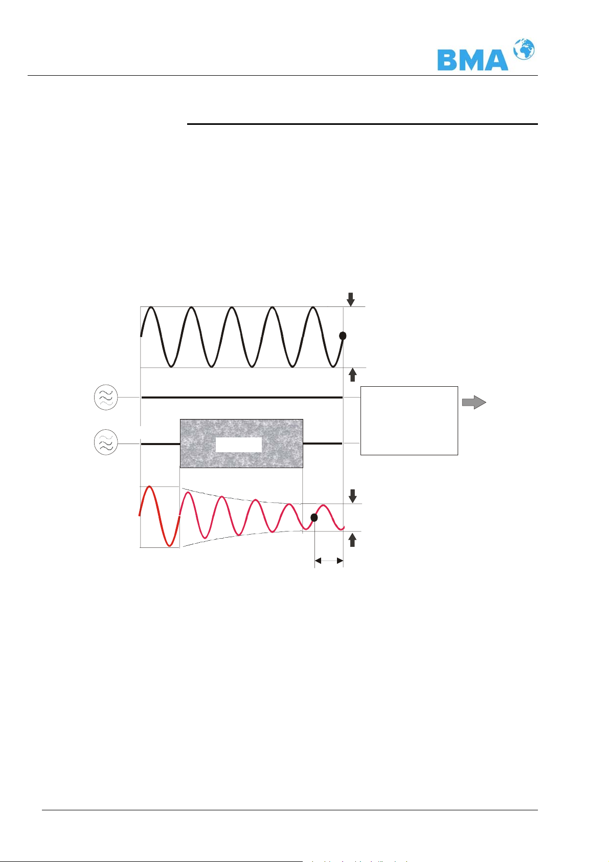
3.1 Principle of Measurement
The microwaves that spread between the rods pass through the
product being measured; their propagation speed is slowed down
(= phase shift) and their intensity is damped (= attenuation).
Figure 3-1 illustrates the principle of measurement: the propagation speed of microwaves passing through the product being
measured is slowed down (phase shift) and their intensity (attenuation) is reduced, relative to a reference signal.
HF- sources
Figure 3-1:
Schematic diagram:
Change of microwave
by product
Transmitte
Reference signal
Reference path
Phase comparison
--> Phase
Product
Receive
Amplitude comp
--> Attenuation
Measured value:
Concentration %TS
Measurement signal
Phase shift
Prerequisite is that the product being measured shows some
dielectric properties. In general, water is a very distinct dielectric fluid. The water or dry mass concentration, respectively, can
therefore be determined by measuring the phase shift and/or
attenuation.
The concentration to be detected in the product is therefore dependent in good approximation linear on phase shift and attenuation. For this reason we can measure the concentration or
the Brix content of the product using a linear calibration (see
chapter 3.2 Calculation of Measured Values ).
16
DynFAS MW
Page 17

Chapter 3 System Description
+ϕ⋅
3.2 Calculation of Measured Values
The microwave measuring phase and attenuation are calibrated
after an automatic plausibility analysis.
During calibration, the phase and/or the attenuation or a concentration value (or density value) are assigned by sampling. The
calibration is full automatic and the sample taking is supported by
the control unit.
Which of the parameters, either phase, attenuation or both are
used for the calibration depends on the size and interference of the
measuring effect. For example, the attenuat ion is significantly
more sensitive to electrolytic conductivity (salt content).
In many cases, the mere phase measurement is recommended
and is calculated in good approximation by a linear calibration as
follows:
=
Con concentration
A, C coefficients of respective calibration function
ϕ phase
The DynFAS MW allows you to calibrate, display and output two
concentrations Con1 and Con2. You have to enter the calibration
coefficients separately for concentration 1 and 2. For more information please refer to the Software Manual.
CACon
DynFAS MW
17
Page 18

Chapter 3 System Description
θΔ⋅
+
θΔ⋅
+
3.3 Temperature Compensation
Temperature compensation (TC) is necessary if the product temperature varies. In general, we recommend connecting a temperature compensation, i.e. a temperature signal (0/4...20 mA or
Pt 100) to the control unit and, if necessary, to enable the compensation in the control unit. The control unit is designed such that
the required TC’s can be calculated automatically. The variat ion in
temperature where temperature compensation becomes absolutely
essential is dependent on the product and on the water content. In
first approximation, ± 2°C should be set as fluctuation limit.
Tip
TC has to be carried out whenever you are working with.
The TC corrects the phase and attenuation before the measured
value calculation (calibration), in most applications according to
the following formulae (linear compensation, additive).
ϕ=ϕ
=
C
meascomp
CDD
ϕ
Dmeascomp
Where
= measured phase
ϕ
meas
ϕ
= compensated phase
comp
= measured attenuation
D
meas
= compensated attenuation
D
meas
= temperature coefficient
C
ϕ
= temperature coefficient
C
D
Δθ = measured temperature (T
) – reference temp. (T
meas
Ref
)
Depending on the selected function (additive, multiplicative, lin ear,
quadratic), the required temperature coefficients appear on the
Calibration menu. Temperature coefficients that are not used are
set to zero.
If you select two-range calibration (split concentration), separate
TC’s have to be entered for both concentration ranges. The coefficients are entered in the course of calibration.
TC can be carried out via Pt 100 or via current input. This has to
be defined on the Calibration menu. The Pt 100 temperature range
is between –50°C and +200°C.
How to work with the temperature compensation is described in
detail in the Software Manual.
18
DynFAS MW
Page 19
Chapter 3 System Description
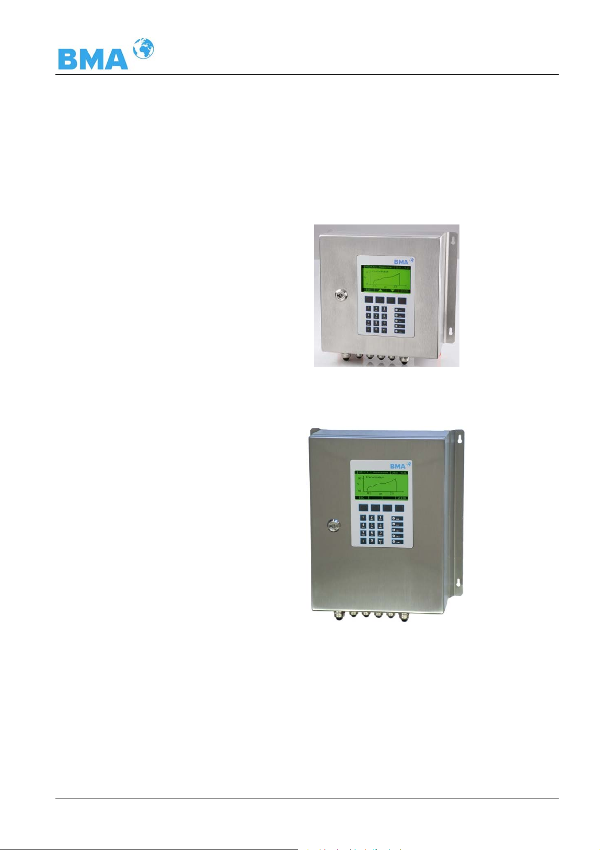
Figure 3-2:
Control Unit Standard
CS-100
3.4 Mechanical Components
The measurement system consists of a control unit, a probe and a
set of special high frequency cables (in short HF-cable). The control unit is available in two versions: the standard model CS-100
and the high dynamic version CH-200, see Figure 3-2 and 3-3.
DynFAS MW
Figure 3-3:
Control Unit
High Dynamic
CH-200
19
Page 20
Chapter 3 System Description
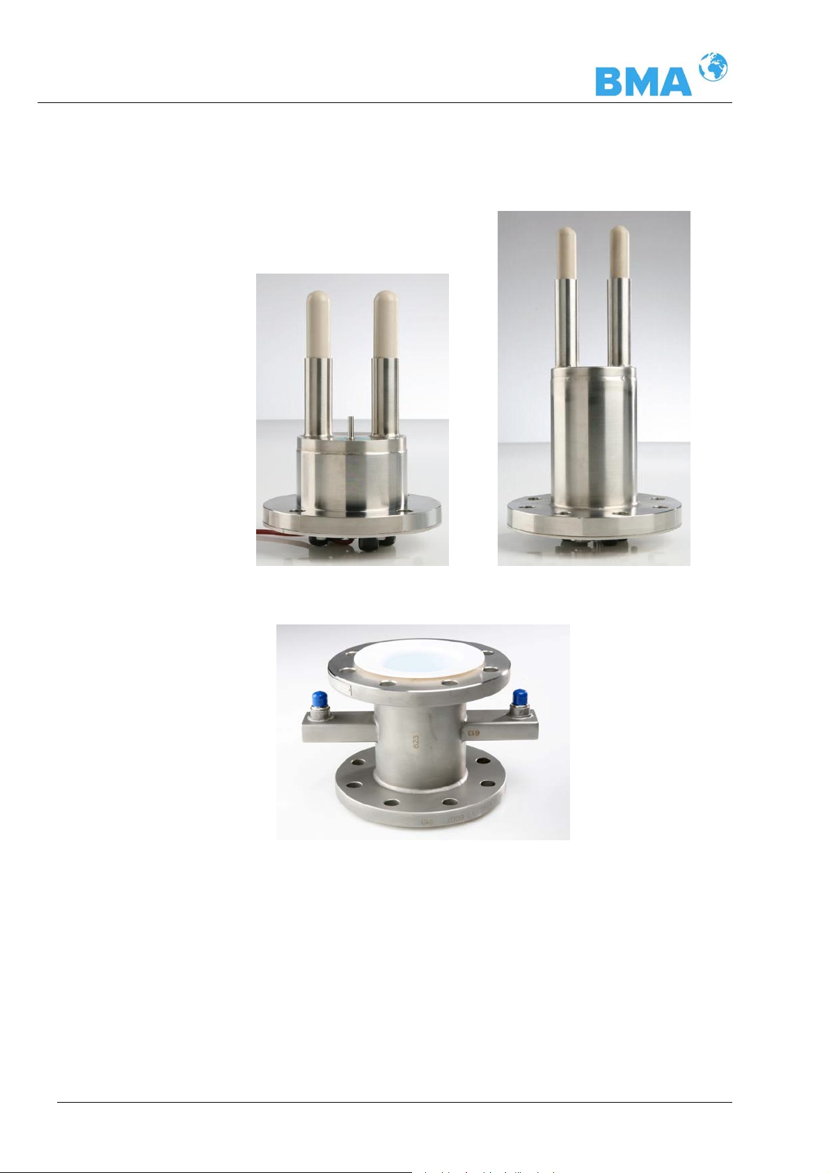
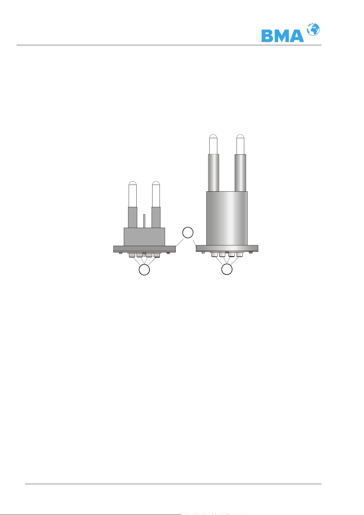
The probes are available in different versions, as pipeline and container probe with and without flushing device (see Figure 3-4, 3-5
and 3-6).
Abb. 3-4 left:
Probe
Abb. 3-5 right:
Probe with Flushing
Figure 3-6:
nominal width 50 mm
Flow Cell
3.4.1 Control Units
The control units consist of evaluation analyser with microwave
unit. The microwaves are generated, received and analyzed by the
microwave unit. Signal processing and communication take place
in the evaluation computer. For simple operation, the measuring
system includes a display, 4 softkeys and an alphanumeric keypad.
Different functions are assigned to the softkeys on the display.
20
DynFAS MW
Page 21
Chapter 3 System Description
High Dynamic Version
CH-200
Differences between Control Unit Standard CS-100 and
Control Unit High Dynamic CH-200
The Control Unit High Dynamic CH-200, has an additional HF amplifier module in comparison to the standard model, whereby the
wall housing is larger (dimensions see chapter 6.2 Technical Data
control unit). Otherwise, the control units only differ in their applications.
Higher product attenuations are allowed for the high dynamic version of DynFAS MW. Therefore larger measuring paths can be irradiated, for example measuring cells of larger nominal width can be
used. The application of both control units is predetermined by the
product attenuation. Up to an attenuation of 50 dB, CS-100 is used
and beyond, CH-200. The CH-200 generally requires an attenuation of 40 dB. If this is lower, the software indicates an err or message.
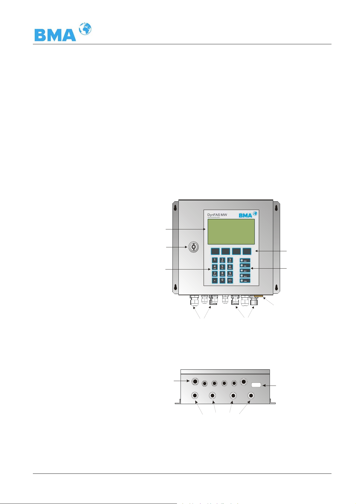
An RS232 interface is included on the underside of the instrument.
Figure 3-7:
Front view of
CS-100
LCD display
Lock
Numerical
keypad
Cable feed-through
M 20 and M 16
HF connections for
signal cable reference cable
and cable feed-through
M-TxM-Rx R-Tx
R-Rx
Softkey buttons
LED’s
RS232 connection
RS232
9-pole Sub-D-connector
Figure 3-8:
Control Unit -
bottom view
DynFAS MW
High-frequency connections
21
Page 22
Chapter 3 System Description
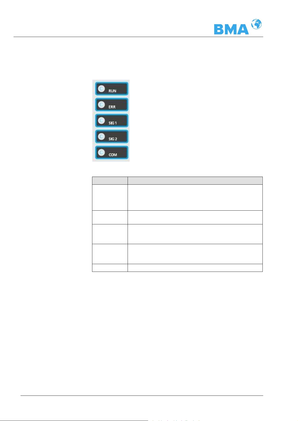
LED’s on the Front Panel
Five LED’s on the instrument front panel indicate the instrument
status.
Figure 3-9:
LED’s on the front panel
of the Control Unit
LED Function
RUN Instrument in measurement mode
Display is flashing when concentration average
value is put on hold, e.g. if an error has occurred,
if the measurement has been paused or stopped
ERR Error
Goes out after reset or if fault has been repaired
SIG 1 Display depending on the selected function of relay
1, possible functions: error, no product, limit value
min., limit value max., measurement stopped
SIG 2 Display depending on the selected function of relay
2, possible functions: error, no product, limit value
min., limit value max., measurement stopped.
COM Communication active, e.g. via RS 232
Terminal Block
The electrical connections of the DynFAS MW are located on a connector strip in the wall housing. The terminal block is accessible
from the front after you have opened the cover. There, you also
find the power cut-off switch and the fuses. The high-frequency
connections are located on the outside of the housing. All other
elements, especially the live elements (on the motherboard) are
provided with a protection cap.
22
DynFAS MW
Page 23
Chapter 3 System Description
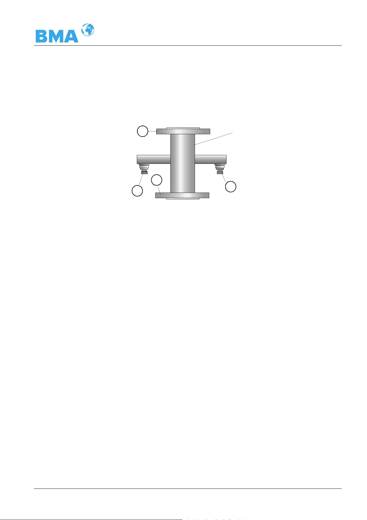
3.4.2 Flow Cell
The flow cells are available with nominal widths from 50 to 150
mm (see Figure 3-10) and different flanges. For technical data
please refer to chapter 6.2.
Figure 3-10:
Flow Cell
B
Pipeline with
nominal width
50 ... 150 mm
B
A
A: High-frequency connections
B: Process connection, flanges of different sizes
The flow cell consists of a sturdy stainless steel body. The microwave transmitter and receiver are firmly welded to the outside of
the pipe. The entire product pipe is PTFE-coated and fulfills the
special requirements for use in foodstuffs.
There are not objects extending into the pipe (such as measuring
sensors). The flow cell can be installed in the pipeline via flange.
A
DynFAS MW
The flow cell has two HF connections to feed in and output microwave signals. Input and output can be allocated as needed (M-Tx,
M-Rx). The microwave signals transmit the product over the entire
pipeline cross-section.
23
Page 24
Chapter 3 System Description
A
3.4.3 Container Probe
Two different container probe versions are available – either with
or without flushing device (see Figure 3-11). For technical data
please refer to chapter 6.2 Technical Data.
Probe
with flushing device
Probe
without flushing device
Figure 3-11:
Container probes
B
A
A: High-frequency connections
B: Process connection, flanges of different sizes
The container probe has been specially designed for concentration
measurements in containers. Both measuring rods are immersed
into the product. Microwaves are emitted from one end of the rod
and received by the other end of the rod; they are emitted only
towards the opposite end of the rod. This direction characteristic of
the probe minimizes the interfering influence of metal parts in the
vicinity of the probe and allows installation if only little space is
available. For example, the concentration of sugar strike can be
measured continuously to find the suitable inoculation time.
The plastic rods meet the special requirements for application in
foodstuffs.
24
DynFAS MW
Page 25
Chapter 3 System Description
Two different probe types are available:
¾ The standard type is the container probe without flushing de-
vice
¾ The probe with flushing is employed in processes where incrus-
tations are likely to occur, for example, due to increased depositions. The flushing device prevents any deposition on the microwave exit windows. Long travel times are supported by continuous crystal processes (i.e. VKT).
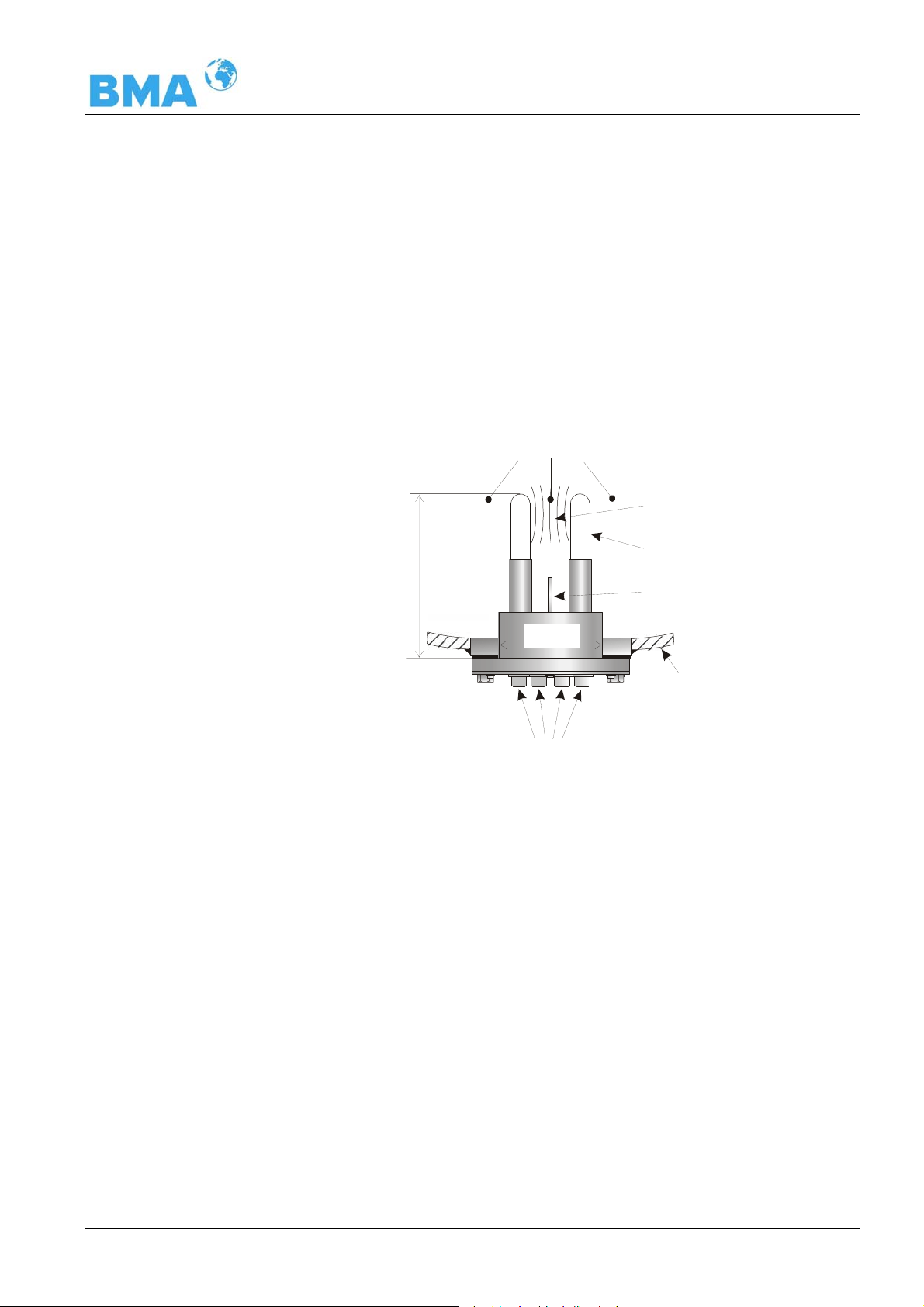
The flow direction of the product being measured should be vertical, as shown in Figure 3-12. This ensures that the product between the measuring rods is representative, provided it is mixed
thoroughly.
Product
Microwave
measur in g f ield
Plastic rods
~ 190 mm
100 mm
Pt100
Container wall
Figure 3-12:
Probe
HF conne ct ions
Pt 100 Only the probe without flushing is provided with a Pt 100 and is
connected to the control unit via 4-wire cable. The wiring diagram
for the Pt 100 is described in chapter 4.3.2 Pin Configuration of the
Connector Strip. To reduce the danger of incrustation in the immediate vicinity of the measuring rods, the probe with flushing is not
provided with a Pt 100.
DynFAS MW
25
Page 26
Chapter 3 System Description
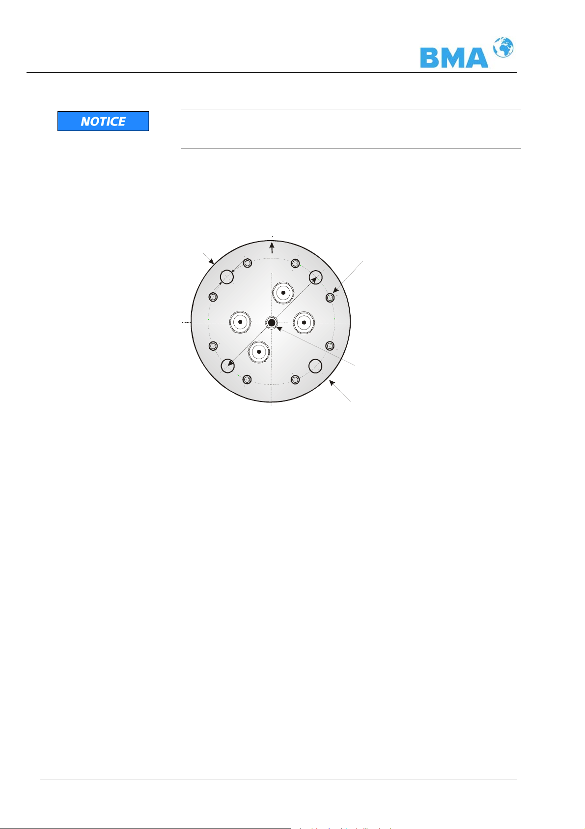
Warning, possible property damages!
Do not open the cover screws on the front of the container probes,
see Figure 3-13.
Probe flange
e.g. Probe DN65 / PN6
Figure 3-13:
The front of the probe
Flow
4
1
Strömung
ø
R-Tx
M-Rx
ø
1
30
R-Rx
M-Tx
do not remove!
PT100
ø
16
0
Probe with Flushing
The probe with flushing device has been designed for processes
where depositions, for example, due to incrustations are likely to
occur on the probe.
26
The flush probe has two flushing channels which keep the plastic
rod free from incrustations; this ensures that the microwaves
come into direct contact with the product being measured. All
parts coming into contact with the product meet the specific requirements for application in foodstuffs. Figure 3-14 shows the
probe design.
DynFAS MW
Page 27
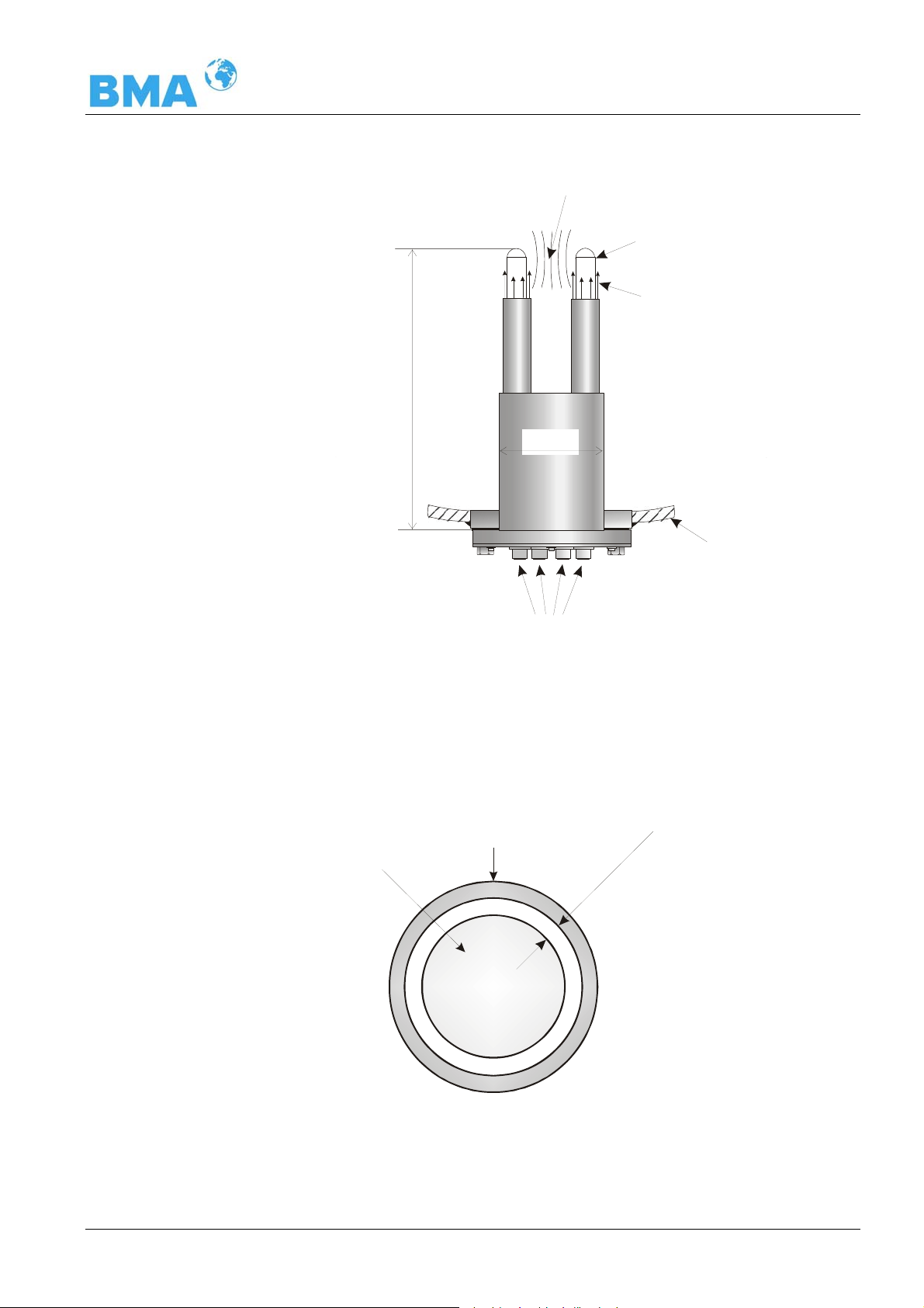
Chapter 3 System Description
Microwave
measuring field
Plastic rods
Rinsing medium
~ 320 mm
100 mm
Container wall
Figure 3-14:
Probe with Flushing
Figure 3-15:
Rod head
with flushing pipe
4 x HF connections
2 x 3/8’’ Flushing connections, internal thread
The flushing slit width is the same for both probe rods and shown
in Figure 3-15.
Flushing pipe
Plastic rods
F
lush
ng slit
i
.5
m
m
~ 1
DynFAS MW
27
Page 28
Chapter 3 System Description
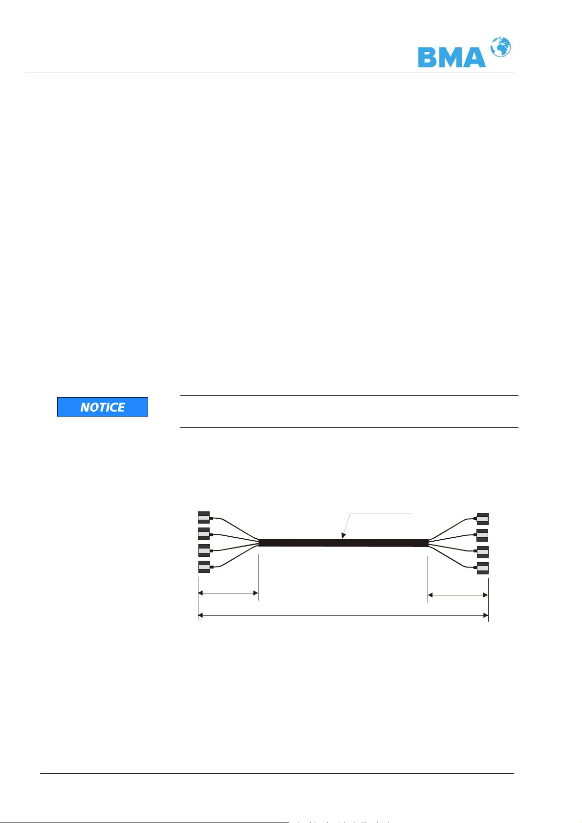
3.4.4 High-Frequency Cable
High-frequency cables (HF cable) are used to transmit microwaves
between probe and evaluation electronics.
HF cables change their conductivity (for microwaves) relative to
the temperature. Therefore, variations in the ambient temperature
would create measurement errors. This error is compensated for
by enabling the cable compensation. Influences of the ambient
temperature on the signal cable are compensated for by means of
the reference cable. The reference cable has the same length as
the signal cable; during operation, it should be exposed to the
same ambient temperature. Therefore, we recommend installing
both cable types together in a corrugated tube; this also simplifies
installation.
The HF cable quad (see Figure 3-16) consists of four individual HF
cables of the same length, which each end with one HF plug connector (N-type). Available cable lengths: 2, 4, 6 and 10 m.
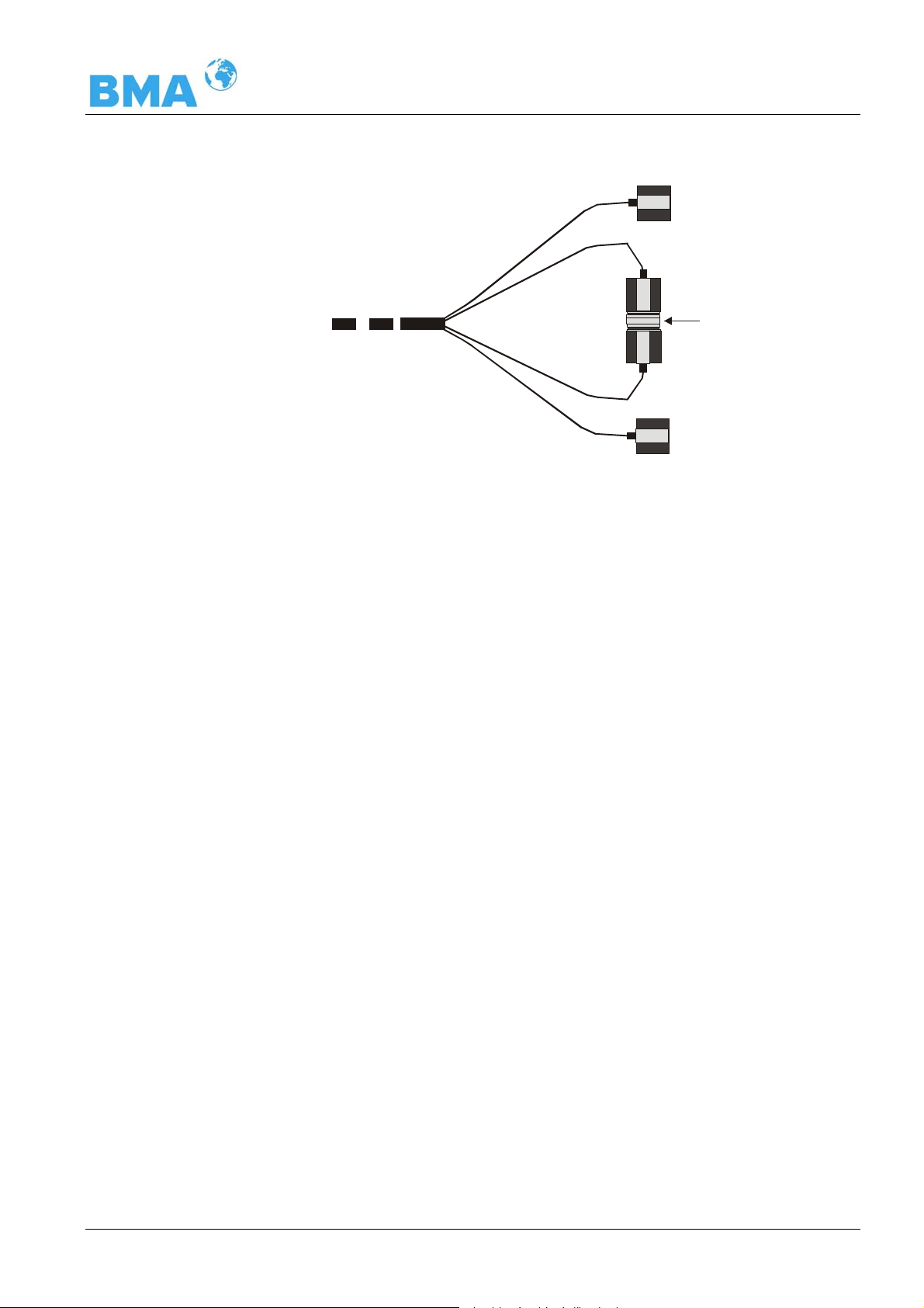
When connecting the Flow Cell, the reference cable is shortcircuited to the probe side by means of N-connectors (see Figure
3-17).
Figure 3-16:
HF-cable quad
Never bend HF cables! The bending radius should not be less than
100 mm. After installation, fix cables with cable binders.
4 x N-connector
4 x N-
0.35 m
ø
18.5 mm
Corrugated tube
Lengths 2, 4, 6 and 10 m
4 x N-connector
0.35 m
28
DynFAS MW
Page 29
Chapter 3 System Description
Figure 3-17:
HF-cable quad, at the
side of the probe
Sensor side
x
R
-
M
x
R
-
R
N-connector
CC-100
R
-
T
x
M
-
T
x
Figure 3-17: The ends of the reference cable R-Rx and R-Tx are
short-circuited with an N-connector.
For further technical data see chapter 6.3 Technical Data HFCable.
DynFAS MW
29
Page 30
Chapter 3 System Description
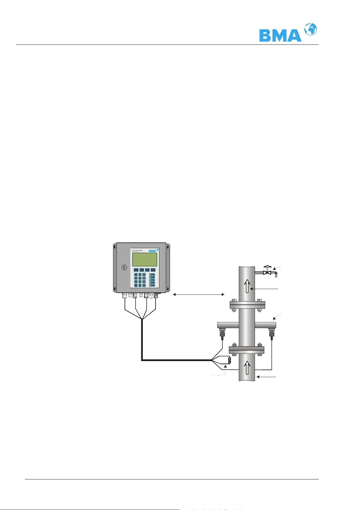
3.5 Pipeline Measurement Configuration
The control unit is installed in the immediate vicinity of the container probe to keep the HF-cable between control unit and probe
fairly short. The shorter the cable connection, the better the stability of the measurement. The standard length is 4 m and the maximum length of the HF-cables is 10 m.
The flow cell is installed into the exist ing pipeline system inline or
into a bypass. The orientation of the flow cell may either be vertical or horizontal. To rule out sedimentary depositions, vertical installation in a riser is preferred (see Figure 3-18).
The flow cell should be installed fairly close to the sampling location to ensure representative sampling for calibration.
For possibly required product temperature compensation, a representative temperature signal (current signal or Pt 100) has to be
connected to the control unit.
Figure 3-18:
Typical measurement
configuration
on a pipeline
Control Unit
Sampling
Distance:
typical 4 m
HF-cable quad
Reference line
with N-connector
CC-100
Product flow
Orientation:
HF-connections
facing down
Pipeline inline
or in bypass
30
DynFAS MW
Page 31

Chapter 3 System Description
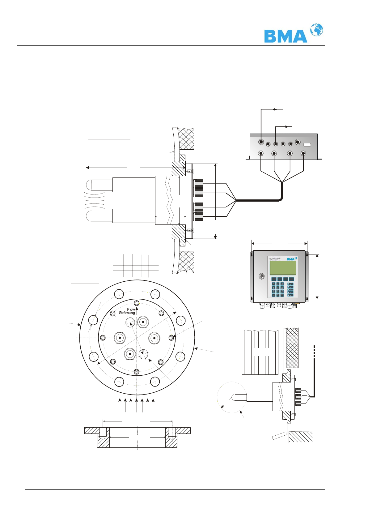
3.6 Container Measurement Configuration
The control unit is installed in the immediate vicinity of the probe
to keep the HF-cable between control unit and probe fairly short.
The shorter the cable connection, the better the stability of the
measurement. The standard length is 2 or 4 m and the maximum
length of the HF-cables is 10 m.
The control unit should be installed fairly close to the sampling
location to ensure representative sampling for calibration. A representative temperature signal (current signal or Pt 100) should be
connected to the control unit for possibly required product temperature compensation.
Our example below shows the measurement configuration on a
discontinuous evaporation crystallizer. The probe is fixed to the
container wall such that both measuring rods are immersed into
the product.
Figure 3-19:
Typical system
configuration on a
evaporation
crystallizer
Distance typical 4 m
(no radiation heat)
a
a > 60 mm
Container wall
PT-100
HF quad cable
Product
HF connections
Microwave
measuring field
Pt100
DynFAS MW
31
Page 32

Chapter 4 Getting Started
Chapter 4. Getting Started
4.1 Transport
IMPORTANT
Risk of damage!
System parts may get damaged during transportation!
Transport probe and control unit in their original packaging. Protect parts against shocks. Especially the plastic rods of the container probes have to be protected against mechanical impact!
After unpacking, make sure all parts listed on the packing list have
been delivered and show no sign of damage; if necessary, clean
these parts.
If you detect any damage, please notify the forwarder and the
manufacturer immediately.
The weight of the system components can amount to more than
25 kg depending on the model. You should wear safety shoes.
4.2 Installation
4.2.1 Flow Cell Installation
For installation of the flow cell please keep in mind:
¾ The flow cell is installed into the pipelin e system. Keep in mind
that material sampling should be possible for calibration directly behind the flow cell.
¾ The flow cell should be installed in a vertical riser, if possible. It
has to be ensured that no material depositions occur on the pipe walls and no bubbles are present in the product. For horizontal installation, please observe the correct orientation of the
HF-connections (see Figure 4-2).
32
¾ There should be a straight pipe section of at least 200 mm and
equal nominal width before and after the flow cell to ensure a
fairly homogeneous flow profile and to rule out possibly occurring microwave reflections in the pipeline.
DynFAS MW
Page 33

Chapter 4 Getting Started
¾ No gas bubbles should be present in the product. If gas bub-
bles cannot be ruled out, a pressure of at least 4 bar is required in the pipeline to minimize the influence of gas bubbles.
Please observe the max. permissible working pressure (see
chapter 6.2 Technical Data Sensors)
¾ The high-frequency cable should preferably be connected to
the flow cell from below to prevent inflowing water from getting
to the connecting sockets.
¾ The HF cable should not come into contact with the warm pipe-
lines.
Figure 4-1:
Installation in a
vertical riser
HF-connections
min. 200 mm
Flow cell
Orientation:
facing down
M-Rx
( M-Tx )
Wrong arrangement !
Sampling
Product flow
Flange
200 ... 250 Nm
HF-connections
max. 2 Nm
M-Tx
( M-Rx )
Pipeline inline
or in bypass
Correct arrangeme nt !
Figure 4-2:
Horizontal installation:
orientation of
HF-connections
DynFAS MW
33
Page 34

Chapter 4 Getting Started
4.2.2 Container Probe Installation
For installation, please keep in mind:
¾ Select the installation site such that good mixing and a homo-
geneous product are ensured and no bubbles are present in the
probe. A tap should be provided in the direct vicinity to allow
representative sampling.
¾ The probe has to be flange-mounted on the container such that
the product being measured flows between both measuring
rods. That means the fork (both measuring rods) has to be installed at an angle of 90° to the material flow.
¾ The distance between the measuring rod tips and any metal-
ized walls (heating elements, stirrer, container wall) should be
at least 60 mm.
¾ The following installation hole sizes in the fitting flange
are required for installation of the probe:
Flange
DN 65 / PN 6
others
¾ For further installation dimensions please refer to chapter 8
(see installation sheets).
¾ Use the respective flat gasket (standard accessory) to compen-
sate for minor surface tolerances in the fitting flange.
Minimum installation hole size ∅ (mm)
100 ± 0.2
102 ± 0.5
Installation on Process Containers
Figure 3-19 shows the position of the container probe on the container. This position is also valid for the container flus h probe.
The assembly sheet in chapter 8 includes all the inf ormation required for installation.
Installation in Pipelines
The container probes can be installed in pipelines with a nominal
width ≥ 200 mm using an adapter flange. Please observe the position and orientation of the container probe (see the technical
drawings in chapters 8.4.7 and 8.5.6 Installation Situation in Pipelines).
34
DynFAS MW
Page 35

Chapter 4 Getting Started
Connection of the flushing pipes
The container probe with flushing device consists of two flushing
devices with a 3/8 inch inner thread (DIN ISO 228-1). The flushing
connections are subsequently sealed to this thread. A sealing to
the probe cover is not permitted, for example with silicone.
Flush Parameters (only for container flush probe)
The degree of deposition or incrustation is essential for the flush
parameters, i.e. flush frequency and duration. The flush parameters have to be adapted to the product and the process.
The following independent flushing parameters for products and
processes have to be observed:
Flush solution water, condensation
Temperature of
flush solution
Pressure
Fittings 2 x 3/8 inch female screw thread
Supply pipe
Independent flushing parameters product and process, typical
starting rates:
Interval every 2 hours
Duration 12 seconds
Temperature of
flush solution
For measurements on the C-product the flushing intervals can be
considerably reduced, e.g. every 6 hours for 30 seconds.
Maximum 120 °C
≥ 3 bar, max. 8 bar
(DIN ISO 228-1)
≥ 1/2 inch
average product temperature, mostly 65 ±5°C
Amount of water
DynFAS MW
The following is generally valid: the flushing devices can be
flushed simultaneously or in shifts. The flushing parameters are
valid for every flushing device.
Tip
The required flush duration has to take into account a possible
inertness of the system, e.g. valve openings. The flush supply
pipes have to be insulated well against heat to prevent that the
flush solution is initially colder.
The amount of water per flushing connector is approx. 0.8 l/sec at
a flushing pressure of 5 bars.
35
Page 36

Chapter 4 Getting Started
4.2.3 Installing the Control Unit
For installation of the control unit, please keep in mind:
¾ Install the control unit in the vicinity of the microwave probe,
keeping in mind the length of the HF cable. HF cables are
available in a length of 2, 4, 6 and 10 m; the standard cable
length are 2 or 4 m.
¾ Protect the instrument against vibrations.
¾ For instrument installation you should foresee a cutoff device to
allow easy and quick disconnection of the device from the
power supply.
¾ When installing the control unit on a crystallizer, use a distance
rail to minimize thermal radiation and heat conduction. See
Figure 4-3.
¾ When the control unit is set-up outdoors, it has to be protected
from direct sunshine and rain for example by means of an adequately large protective roof.
Figure 4-3:
View from above:
Installation of
control unit
on a crystallizer
Insulation container wall
Spacer
Control Unit
36
DynFAS MW
Page 37

Chapter 4 Getting Started
4.3 Connecting the Control Unit
4.3.1 Connecting the HF Cable
For the connection of the sensor with the control unit, you will
need a HF cable quad. Additionally, the flow cell requires an Nconnector.
Prerequisite for a proper measurement is the correct installation of
cables! Please keep in mind:
IMPORTANT
Make sure the cables do not get into contact with hot pipes over
the entire length (corrugated tube and single cable section after
splitting), e.g. direct contact with the device wall (not insulated).
This alone guarantees that all single cables are subject to the same ambient conditions and that the compensation of the cable
drift works properly.
Never bend HF cables! The bending radius should not be less than
100 mm. After installation, fix the cables with cable binders to
prevent the cable from slipping!
Connecting the Flow Cell
The HF-cable quad and the HF-connections on the control unit are
labeled. Connect the flow cell to the control unit as shown in Figure
4-4 and make sure that you only connect cables with equal labeling. The two connections on the flow cell are not labeled, the allocation of the cable connectors M-Tx and M-Rx is arbitrary. The cable plugs R-Tx and R-Mx are connector to the N-connector (shortcircuited).
DynFAS MW
37
Page 38

Chapter 4 Getting Started
Control Unit,
underside
Figure 4-4:
Connection of flow cell
version 1
M-Rx
M-Rx
Bending radius
min. 100 mm
M-Tx
M-Tx
R-Tx
R-Rx
R-Rx
R-Tx
HF-cable quad
(stand ard 4 m)
Flow cell
Reference line
with N-connector
Flange
200 ... 250 Nm
HF-connections
max. 2 Nm
M-Rx
( M-Tx )
R-Rx
R-Tx
M-Tx
( M-Rx )
Connecting the Container Probes
The HF cables and the HF connections on the control unit and on
the probe are labeled. Connect the flow cell to the control unit as
shown in Figure 4-5, and make sure that you only connect cables
with equal labeling.
Figure 4-5:
Connection of the
container probe to
the control unit
Microwave
measuring field
Control Unit, underside
M-Rx
M-Rx
M-Tx
R-Tx
ø100
R-Rx
M-Rx
PT-100
HF quad cable
M-Tx
M-Tx
R-Tx
R-Rx
R-Rx
R-Tx
38
DynFAS MW
Page 39

Chapter 4 Getting Started
IMPORTANT
When tightening the 21 mm screw nut, make sure that the connector is not twisted on the cable. If the connector is twisted relative to the cable, the shielding may get damaged and this could
result in mismatching and bad sealing.
Hand tighten all screwed connections of the HF cable (2 Nm = 0.2
kg/m)! Before tightening, carefully screw on the cable by hand.
Caution! Threaded joint jams easily.
Occasionally you should check if the screwed connection is still
properly tightened. If the installation is ex posed to vibrations, the
screwed connection may come loose and this may result in inaccurate measurements or corrosion of the connections.
As long as the cables are not connected, the coaxial sockets have
to be covered immediately with plastic caps and the cable connectors have to be protected by suitable provisions against moisture
and dirt.
DynFAS MW
39
Page 40

Chapter 4 Getting Started
4.3.2 Pin Configuration of the Connector Strip
Electrical shock hazard:
Disconnect power to rule out any contact with live parts during
installation and when servicing.
Turn off power supply before opening the instrument. NEVER work
on open and live instruments.
Temperature Signal Connection
A Pt 100 or a temperature current signal has to be connected to
current input 1 or 2 if temperature fluctuations occur in the product and if a temperature dependence of the phase or attenuation
measurement is likely to occur. The temperature sensor has to
measure the material temperature in the vicinity of the microwave
probe.
When taking the container probe into operation, connect the 4wire
cable of the Pt 100 to the connector strip of the control unit as
follows:
Figure 4-6:
Pt 100 connection
container probe
Contr o l Unit
Connector strip
(23)
(11)
( ) Terminal no.
blue
blue
white
white
PT-100 sensor
in the container
probe
40
DynFAS MW
Page 41

Chapter 4 Getting Started
Other Connections
¾ Connect all desired input and output signals to the terminal
strip as shown below. Use the M feed-through to maintain the
degree of protection.
¾ Check if the voltage indicated on the type plate matches your
local supply voltage.
¾ Connect the line cable to the terminals 3(L1), 2(N) and 1(PE).
¾ Check if the test switch (mains interru ption) is in position „on“
(see Figure 5-1).
¾ Close the instrument housing and turn on the power supply.
Attention! Possible danger, damage to property! Concerns the system type CH-200-024 Control Unit High Dynamic 24 V DC (Id.-No.
54878-02):
When connecting the 24 V DC auxiliary power, the + and – Poles
should be connected correctly. There is no reverse voltage protection!
The line cross-section for the power supply must be at least
1.0 mm
2
.
On the connector strip of the control unit you find the following
connections:
or / bzw.
DynFAS MW
Figure 4-7:
DynFAS MW
wiring diagram
- +
41
Page 42

Chapter 4 Getting Started
Power supply: Terminals 3 (L1, +), 2 (N, -) and 1 (PE, )
For CS-100, depending on instrument version, see type label on
the outer wall of the housing.
1.) 90 V - 265 V AC, 45 - 65 Hz
2.) 24 V DC: 18 … 36 V
24 V AC: -20%, +5%, 40 … 440 Hz
For CH-200, depending on instrument version, see type label on
the outer wall of the housing.
1.) 90 V - 265 V AC, 45 - 65 Hz
2.) 24 V DC: 18 … 36 V, no reverse voltage protection
Current input no. 1 (terminals 20+ and 8-), insulated
Input as 0/4 - 20 mA signal. e.g. for temperature compensation or
reference signal recording.
Current input no. 2 (terminals 22+ and 10-), not insulated
Input as 0/4 - 20 mA signal. e.g. for temperature compensation or
reference signal recording.
Current output no. 1 (terminals 27+ and 15-), insulated
Output as 4 - 20 mA signal. Output options: concentrations (1/2),
current inputs signals (1 / 2) and Pt 100 signal
Current output no. 2 (terminals 19+ and 7-), insulated
Output as 0/4 - 20 mA signal. Output options: concentrations
1 and 2, current input signals 1 and 2 and Pt 100 signal
Pt 100 (terminals 23+ and 11-)
Connection for temperature measurement.
Digital input 1: DI1 (terminals 24+ and 12-)
Configuration options:
¾ no function
¾ measurement: start (closed) and stop (open)
Digital input 2: DI2 (terminals 25+ and 13-)
Configuration options:
42
¾ no function
¾ average value: hold (closed) and continue averaging (open)
¾ product selection: product 1 (open) and product 2 (closed)
DynFAS MW
Page 43

Chapter 4 Getting Started
Digital input 3: DI3 (terminals 26+ and 14-)
Configuration options:
¾ no function
¾ start sampling, open: no action, closed: unique measurement
starts
¾ product selection
Relay 1: (terminals 4, 5 and 6)
Changeover contacts (SPDT), insulated, configuration option:
¾ no function
¾ error message
¾ stop measurement
¾ limit value min. and max.
¾ no product
Relay 2: (terminals 16, 17 and 18)
Changeover contacts (SPDT), insulated, configuration option:
¾ no function
¾ error message
¾ stop measurement
¾ limit value min. and max.
¾ no product
RS485 interface (terminals 21 (RS1) and 9 (RS2))
Serial data interface for output of live data (all measuring data for
every sweep, measuring cycle) the setup protocol and data log.
Data format: 38400 baud, 8 data bits, 1 stop bit, no parity, no
handshake.
RS232 interface (on instrument bottom)
9-pole SubD-connector. Serial data interface for output of live data
(all measuring data for every sweep, measuring cycle) the setup
protocol and data log.
Data format: 38400 baud (Data transfer rate ), 8 data bits, 1 stop
bit, no parity, no handshake.
DynFAS MW
43
Page 44

Chapter 4 Getting Started
5 6
4.3.3 Digital Outputs, Relays
The status of the measurement is output via two relays:
¾ Error
¾ Alarm (alarm min. and max.)
¾ No product
Under menu item Plausibility, you may enter a min. attenuation
for pause detection (e.g. for process pause, no product present); if this value is not reached, „no product“ is sign aled via a
relay and the current output drops to 0 or 4 mA.
A typical application is pause detection between t he discontinu-
ous evaporation crystal processes.
¾ Measurement stopped
The respective switching status is also signaled via LED’s on the
front panel (LED’s: signal 1 and 2).
Relay no. Error, alarm, no product,
measurement stopped,
currentless status
4
Normal
4
1
com
5
6
com
2
16
17
18
com
16
17
18
com
The relays with changeover contacts can either be operated as
make contact, terminals 4 & 5 (open at error, alarm ...) or as
break contact, terminals 5 & 6 (closed at error, alarm ...).
44
DynFAS MW
Page 45

Chapter 5 Service Instructions
Chapter 5. Service Instructions
5.1 General Information
The control unit has no wearing parts or components requirin g any
special maintenance.
A malfunction of the measuring system is not always due to a defect in the instrument. Often the error is caused by incorrect operation, wrong installation, or irregularities in the product being
measured.
If a malfunction occurs, anyway, the measuring system helps you
to identify and eliminate errors by displaying error messages on
the LCD, indicating operator errors and defects of the electronics.
Usually, faulty modules of the control unit cannot be repaired but
have to be replaced. The microwave module is fixed with screws to
a shielding cover and must not be opened.
5.2 Wearing Parts
The control unit consists of no wearing parts and components that
need special attention.
The plastic rods of the Probes and the PTFE lining of the Flow Cell
can eventually experience abrasion depending on the material being measured. A lower to middle abrasion influences inconsiderably
the measurement or is compensated by calibration. Therefore, you
should check the wearing parts approximately every 2 years.
The plastic rods of the Probe and the lining of the Flow Cell can be
exchanged if abrasion is heavy. During excessive wear, the plastic
rods of the Probe and the lining of the Flow Cells can be exchanged. These Probes and the Flow cells have to be sent back to
the company. An on-site exchange is not possible.
5.3 Instrument Cleaning
Clean all system components using a moistened cloth. Do not use
any chemical cleaning agent. Parts coming into contact with the
product (during regular operation) can be cleaned with hot water,
taking into account the temperature limits (see chapter 6.2
Technical Data Sensors).
DynFAS MW
45
Page 46

Chapter 5 Service Instructions
5.4 Battery
If the measuring system DynFAS MW is without power supply
(power failure or disconnected from mains), the system clock is
supplied with power by the Lithium battery on the CPU. The instrument works correctly even with empty battery, only measured
data which are output via one of the serial interfaces may become
useless as a result of the faulty date and time information.
The service life of the battery, even under continuous load, is at
least 8 years. To replace the battery, you have to disconnect the
instrument from mains.
Battery type: 3 Volt Lithium cell (round cell battery), type CR2032.
5.5 Fuse Replacement
The mains fuse of the DynFAS MW is located in the wall housing.
Replace the fuses only if the instrument is disconnected from
mains. Be sure that the new fuses match the rating specified.
Use only fuses with correct rating:
For CS-100:
Instrument version with 90 ... 265 V AC: 2.0 A slow-blow
Instrument version with 24 V AC/DC: 2.0 A slow-blow
For CH-200:
Instrument version with 90 ... 265 V AC: 2.0 A slow-blow
Instrument version with 24 V DC: 6.3 A slow-blow
Spare fuses must match the rating specified by the device manufacturer. Short-circuiting or manipulation is not permitted.
Netzteil
Test switch Motherboard
I
0
Fuses
Line connecto r
Protective cover
EEprom
(can be pulled off)
Feed-through for
Figure 5-1:
Look inside the
instrument CS-100
46
line connector
Terminal strip
(can be pulled off)
Battery
DynFAS MW
Page 47

Chapter 6 Technical Data
Chapter 6. Technical Data
General Specifications
Method Microwave transmission measurement
Working frequency 2.4 – 2.5 GHz (ISM band), depending on local
regulations
Transmission power CS-100: < 0.1 mW (< -10 dBm)
CH-200: < 10 mW (< 10 dBm)
All coaxial line power
Applications Concentration measurement in containers and
pipes
6.1 Control Unit
Control unit
Housing
Protection type IP 65
Weight CS-100: approx. 6.5 kg
Operating
temperature
Storage
temperature
Achievable
accuracy
Display Dot matrix LC display, 114 mm x 64 mm, 240 x
Keyboard Freely accessible foil keypad, light-stable and
Power supply For CS-100 depending on instrument version:
Wall housing made of stainless steel, material
1.4571 (~316+Ti), see dimensional drawing in
chapter 8.
CS-100: HxWxD: 300 x 323 x 140 mm
CH-200: HxWxD: 400 x 338 x 170 mm
CH-200: approx. 8.0 kg
-20 ... +60°C ( 253 ...333 K ),
Humidity 0 – 90% relatively, no condensation
-20 ... +80°C ( 253 ...353 K ),
Humidity 0 – 90% relatively, no condensation
≤ 0.2 weight % (standard deviation) depending on
product and sensor
128 pixels, with back-lighting, automatic contrast
setting
weatherproof: alphanumeric keyboard and four
softkeys (software-assigned buttons)
1.) 90 ... 265 V AC, 45 ... 65 Hz or
2.) 24 V DC: 18 ... 36 V
24 V AC: -20%, +5%, 40 ... 440 Hz
For CH-200 depending on instrument version:
1.) 90 ... 265 V AC, 45 ... 65 Hz or
2.) 24 V DC: 18 ... 36 V, no reverse voltage protection
DynFAS MW
47
Page 48

Chapter 6 Technical Data
Power
consumption
Fuses For CS-100:
Battery type 3 V Lithium button cell, type CR2032
Measured value e.g. concentration, dry content
For CS-100:
max. 30 VA (AC/DC), depending on configuration
For CH-200:
max. (48/60) VA (AC/DC), depending on configu-
ration
2 x 2.0 A / slow-blow
For CH-200:
2 x 2.0 A / slow-blow for 90 … 265 V AC or
2 x 6.3 A / slow-blow for 24 V DC
Inputs and Outputs
Cable
cross-section
Cable
feed-through
Sensor connection
min. 1.0 mm² (mains supply)
2 x M20x1.5 for cable 5...14 mm (depending on
application)
4 x M16x1.5 for cable 5 ...8 mm
(depending on application)
Inputs and outputs for signal and
reference channel, 50 Ω N-socket
HF-cable
Current input 2 x current input 0/4 ...20 mA, ohmic resistance
Current output
Pt 100
connection
Cable lengths: 2, 4, 6 and 10 m; 50 Ω;
both sides with 4 N connectors
50 Ω, 1x insulated, 1x instrument ground
e.g. for temperature compensation
Current output 1: 4...20 mA, ohmic resistance
max. 800 Ω , insulated
current output 2: 0/4...20 mA, ohmic resistance
max. 800 Ω , insulated
e.g. for measured value or temperature output
Measuring range: -50 ... +200°C (223 ... 473 K);
measurement tolerance: < 0.4°C
48
DynFAS MW
Page 49

Chapter 6 Technical Data
Digital input 3 x digital inputs (DI1..3), for floating connectors
Configuration options:
DI1: none, measurement start/stop
DI2: none, measurement hold, product selection
DI3: none, sampling, product selection
Function description:
1. Measurement (Start/Stop)
open: measurement stopped
closed:
running
2. Hold measurement
open:
closed:
values and current output are held
3. Product selection
open:
closed:
with two DI’s: DI2 open & DI3 open
closed & DI3 open: P2, DI2 open & DI3 closed:
P3, DI2 closed &DI3 closed:
4. Start sampling
open:
closed: single measurement starts
measurement started or measurement
measurement running
measurement stopped, i.e. average
product 1 (P1)
P2;
no actions
: P1, DI2
P4
Relay outputs 2 x relays, insulated
Configuration options:
- Collective failure message
- Stop measurement
- Limit value (alarm min. and max.)
- No product
Load capacity:
AC: max. 400VA
DC: max. 90W
AC / DC: max. 250V, max. 2A, non-inductive
≥ 150V: voltage must be grounded
The cable and insulation that are to be connected
to these cables must correspond to a mains connection.
Restrictions for 24 V AC/DC mains supply, if the
ground conductor is not connected to terminal 1
(PE):
AC: max. 50 V
DC: max. 70 V
Serial interfaces
RS 232 on the underside of the instrument,
RS 485 through terminal block
Data type: 38400 baud, no handshake,
8 data bits, 1 stop bit, no parity
DynFAS MW
49
Page 50

Chapter 6 Technical Data
6.2 Technical Data Sensors
Flow Cells
Application Microwave flow cell with various nominal widths and
flanges for measurement on pipelines
Material Stainless steel, PTFE lining
Process coupling
Process pressure Up to 20 bar (relative), depending on nominal width
Flange according to DIN EN 1092 Type 05 and ASA
and flange type, see table below
Temperature range
Connections
Versions Nominal pipe widths from 50 ... 150 mm
Dimensions See dimensional drawings in chapter 8
Product temperature: +10 ... +130°C (283 … 403 K)
Ambient temperature: -20 ... +60°C (253 … 333 K)
Storage temperature: +10 ... +80°C (283 … 353 K)
2 x HF connections: N-socket, 50 Ω
for HF-cable with max. 10 m length
Overview Flow Cells
Designation ID-No. Nominal
width
Flange Pressure
[bar]
[mm]
FC-050-016 54943 50 DN 50 / PN 16 16
FC-065-040 54944 65 DN 65 / PN 40 20
FC-080-016 54945 80 DN 80 / PN 16 16
FC-100-016 54946 100 DN 100 / PN 16 16
FC-150-016 54941 150 DN 150 / PN 16 16
FC-020-150 54947 50 ASA 2’’ / 150 PSI 16
FC-025-300 54948 65 ASA 2.5’’ / 300 PSI 20
FC-030-150 54949 80 ASA 3’’ / 150 PSI 16
FC-040-150 54950 100 ASA 4” / 150 PSI 16
FC-060-150 54951 150 ASA 6’’ / 150 PSI 16
50
DynFAS MW
Page 51

Chapter 6 Technical Data
Probes
Application Probes with and without flushing
device for concentration measurement in
process containers and pipelines with nominal width
≥ 200 mm.
Material Plastic rod, stainless steel
PT100 connection cable: Silicon / Teflon
Process coupling Flange according to DIN EN 1092 Type 05 DN65 / PN6,
DN 80, 100, 150 / PN16;
ASA flange 2.5’’, 3’’ / 150 PSI
Process pressure Up to 16 bar (relative), depending on model
Temperature range Product temperature: +10 ... +120°C (283 … 393 K)
Ambient temperature: -20 ... +60°C (253 … 333 K)
Storage temperature: +10 ... +80°C (283 … 353 K)
Connections
Dimensions See dimensional drawings in chapter 8
4 x HF connections: N-socket, 50 Ω
for HF-cable with max. 10 m length
Accessory sealing washer
Material Klingersil C-4400
Thickness 3 mm
Overview Probes
Designation ID-No. Flange Pressure
[bar]
P-065-006 54939-01 DN 65 / PN 6 6
P-080-016 54939-02 DN 80 / PN 16 16
P-100-016 54939-03 DN 100 / PN 16 16
P-150-016 54939-04 DN 150 / PN 16 16
P-025-150 54939-05 ASA 2.5’’ / 150 PSI 16
P-030-150 54939-09 ASA 3’’ / 150 PSI 16
DynFAS MW
PF-065-006 54940-01 DN 65 / PN 6 6
PF-080-016 54940-02 DN 80 / PN 16 16
PF-100-016 54940-03 DN 100 / PN 16 16
PF-150-016 54940-04 DN 150 / PN 16 16
PF-025-150 54940-05 ASA 2.5’’ / 150 PSI 16
51
Page 52

Chapter 6 Technical Data
6.3 Technical Data HF-Cable
HF-Cable Quad
Material Corrugated tube: Polyamide (PA6)
Cable sheath: Polyethylene (PE)
Protection type IP 66
Temperature Operating temperature: -30 ... +70°C (243 … 343 K)
Installation temperature: -20 ... +70°C (253… 343 K)
Summary HF-Cable Quad, Cable lengths
Length [m] Id No.
2.0 54856
4.0 54857
6.0 54858
10.0 54859
52
DynFAS MW
Page 53

Chapter 6 Technical Data
6.4 Format of Serial Data Output RS 232 and RS 485
Header
Date·Time→Flags→Status→Product→Att→Phi→R2→Tint→IN1→IN2→Pt 100→C→Cm→C2→C2m
Following lines
01.01.2005·00:00:00→0000→0→1→0.43→5.30→0.07→0.0→0.0→0.0→0.0→75.36→75.00→0.00→0.00
1 2 3 4 5 6 7 8 9 10 11 12 13 14 15
Column no. Description Format
1 Date and time DD.MM.YY·HH:MM:SS
2 Flags (for test purposes) 4 digits, HEX
3 Status: Information on quality of last
measurement
4 Product number X (1 to 4)
5 Attenuation [dB] X.XX
6 Phase [°/GHz] X.XX
7 Statistical spread of phase regression X.XX
8 Instrument temperature [temperature unit] X.X
9 Current input 1 [unit of current input] X.X
10 Current input 2 [unit of current input] X.X
11 Pt 100 temperature [temperature unit] X.X
[…] by selection of unit g/cm
12 Concentration 1 live X.XX [X.XXXX]
13 Concentration 1 averaged X.XX [X.XXXX]
14 Concentration 2 live X.XX [X.XXXX]
15 Concentration 2 averaged X.XX [X.XXXX]
0 : measurement OK
< 0 : error
3
Special characters
“→” Tabulation “¶” Carriage return + Line feed “·” Blank character
DynFAS MW
53
Page 54

Page 55

Chapter 7 Certificates
7.1 EC Declaration of Conformity
Chapter 7. Certificates
DynFAS MW
55
Page 56

Chapter 7 Certificates
56
DynFAS MW
Page 57

Chapter 7 Certificates
7.2 Frequency Approval
DynFAS MW
57
Page 58

Chapter 7 Certificates
58
DynFAS MW
Page 59

Chapter 7 Certificates
DynFAS MW
59
Page 60

Chapter 7 Certificates
60
DynFAS MW
Page 61

Chapter 7 Certificates
DynFAS MW
61
Page 62

Chapter 7 Certificates
62
DynFAS MW
Page 63

Chapter 8 Technical Drawings
Chapter 8. Technical Drawings
8.1 Dimensional Drawing of Control Unit Housing
8.1.1 Control Unit Standard CS-100
DynFAS MW
63
Page 64

Chapter 8 Technical Drawings
8.1.2 Control Unit High Dynamic CH-200
64
DynFAS MW
Page 65

Chapter 8 Technical Drawings
8.2 Electrical Wiring Diagram
Line in for CS-100:
1. / 2. depending on instrument version
1.
AC 90-265V, 45-65 Hz
2.
DC 24 V (18-36 V) or
AC 24 V -20% / +5%, 40-440 Hz
________________________________
Line in for CH-200:
1. / 2. depending on instrument version
1.
AC 90-265V, 45-65 Hz
2.
DC 24 V (18-36 V), no reverse voltage
protection
DynFAS MW
65
Page 66

Chapter 8 Technical Drawings
8.3 Dimensional Drawings Flow Cells
8.3.1 Type FC-050-016
66
DynFAS MW
Page 67
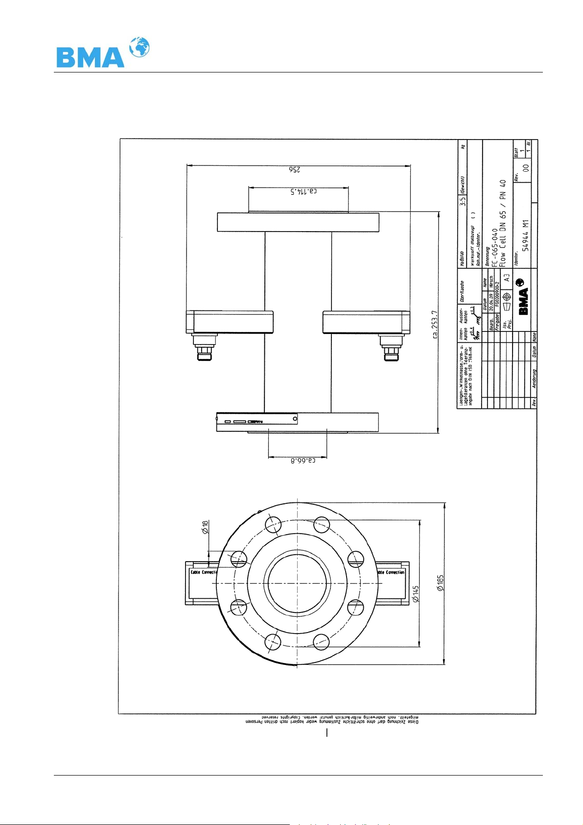
Chapter 8 Technical Drawings
8.3.2 Type FC-065-040
DynFAS MW
67
Page 68

Chapter 8 Technical Drawings
8.3.3 Type FC-080-016
68
DynFAS MW
Page 69

Chapter 8 Technical Drawings
8.3.4 Type FC-100-016
DynFAS MW
69
Page 70

Chapter 8 Technical Drawings
8.3.5 Type FC-150-016
70
DynFAS MW
Page 71

Chapter 8 Technical Drawings
8.3.6 Type FC-020-150
DynFAS MW
71
Page 72

Chapter 8 Technical Drawings
8.3.7 Type FC-025-300
72
DynFAS MW
Page 73

Chapter 8 Technical Drawings
8.3.8 Type FC-030-150
DynFAS MW
73
Page 74

Chapter 8 Technical Drawings
8.3.9 Type FC-040-150
74
DynFAS MW
Page 75

Chapter 8 Technical Drawings
8.3.10 Type FC-060-150
DynFAS MW
75
Page 76

Chapter 8 Technical Drawings
8.4 Dimensional Drawings Probes
8.4.1 Type P-065-006
76
DynFAS MW
Page 77

Chapter 8 Technical Drawings
8.4.2 Type P-080-016
DynFAS MW
77
Page 78

Chapter 8 Technical Drawings
8.4.3 Type P-100-016
78
DynFAS MW
Page 79

Chapter 8 Technical Drawings
8.4.4 Type P-150-016
DynFAS MW
79
Page 80

Chapter 8 Technical Drawings
8.4.5 Type P-025-150
80
DynFAS MW
Page 81

Chapter 8 Technical Drawings
8.4.6 Type P-030-150
ll
DynFAS MW
81
Page 82

Chapter 8 Technical Drawings
8.4.7 Installation Situation in Pipelines
82
DynFAS MW
Page 83

Chapter 8 Technical Drawings
8.5 Dimensional Drawings Flush Probes
8.5.1 Type PF-065-006
DynFAS MW
83
Page 84

Chapter 8 Technical Drawings
8.5.2 Type PF-080-016
84
DynFAS MW
Page 85

Chapter 8 Technical Drawings
8.5.3 Type PF-100-016
DynFAS MW
85
Page 86

Chapter 8 Technical Drawings
8.5.4 Type PF-150-016
86
DynFAS MW
Page 87

Chapter 8 Technical Drawings
8.5.5 Type PF-025-150
DynFAS MW
87
Page 88

Chapter 8 Technical Drawings
8.5.6 Installation Situation in Pipelines
88
DynFAS MW
Page 89

Chapter 8 Technical Drawings
8.6 Installation Sheets for DynFAS MW (Probe)
DynF AS MW with Probe
- Installa t ion In Cryst a llizer -
top view into the
crystallizer
evaluation unit
botten side
M-Rx
M-Tx
90 - 265 V AC
or 24 V AC/DC
(24 V DC)
output
0/4 - 20 mA
R-Tx
R-Rx
microwave
measuring field
probe flange DN65 / PN6
14
installation
position
ø
M-Rx
ø
1
30
R-Rx
190
PT100
container wall
Flow
Strömung
R-Tx
M-Tx
60
100
ø
insulation
ø
1
M-Tx
R-Tx
R-Rx
M-Rx
sealing
do not remove!
PT100
6
0
M-Rx
PT100
HF cable quad
M-Tx
R-Rx
R-Tx
Control Unit
160
ø
(...) for CH-200
heating
300
(318)
220
(320)
DynFAS MW
fitting flange
ø
130 / 4 x M12
±
ø
100
current stream
0.2
0
6
area without
metalic
installations
89
Page 90

Chapter 8 Technical Drawings
DynFAS MW with Probe
- Installa tion In C rystallizer -
top view into the
crystallizer
microwave
measuring field
probe flange DN80, 100, 15 0 / PN16
installation
position
DN
80
100
150
container wall
190
PT100
ABC
160
200
18 M16
180 220
18 M16
240
28522M20
60
S
100
ø
sealing
insulation
evaluation unit
botten side
M-Tx
R-Tx
R-Rx
M-Rx
B
ø
M-Rx
M-Rx
PT100
HF cable quad
Control Unit
(...) for CH-200
M-Tx
M-Tx
300
(318)
90 - 265 V AC
or 24 V AC/DC
(24 V DC)
output
0/4 - 20 mA
R-Tx
R-Rx
R-Rx
R-Tx
220
(320)
C
ø
fitting flange
M-Rx
A
ø
R-Rx
ø
R-Tx
A / 8 x S
±
ø
102
M-Tx
current stream
0,5
do not remove!
ø
B
PT100
0
6
area without
metalic
installations
heating
90
DynFAS MW
Page 91

Chapter 8 Technical Drawings
8.7 Installation Sheets for DynFAS MW (Flush Probe)
DynFAS MW with Pro be with Flus hi ng
- Installation In Crystallizer -
top view into the
crystallizer
evaluation unit
botten side
M-Rx
M-Tx
90 - 265 V AC
or 24 V AC/DC
(24 V DC)
output
0/4 - 20 mA
R-Tx
R-Rx
microwave
measuring field
320
container wall
160
M-Tx
R-Tx
100
ø
sealing
R-Rx
M-Rx
160
ø
HF cable quad
M-Tx
M-Rx
Control Unit
(...) for CH-200
300
(318)
R-Rx
R-Tx
probe flange DN65 / PN6
insulation
220
(320)
installation
position
ø
M-Rx
ø
R-Tx
M-Tx
5
5
0
3
1
R-Rx
Flow
14
Strömung
current stream
fitting flange
ø
130 / 4 x M12
±
0,2
ø
100
do not remove!
flushing connection:
intern a l th r e a d
2 x G3/8’’
(DIN ISO 228-1 )
ø
160
heating
60
area without
metalic
installations
DynFAS MW
91
Page 92
Chapter 8 Technical Drawings
DynFAS MW with Probe with Flushing
- Installation In Crystallizer -
top view into the
crystallizer
microwave
measuring field
container wall
320
100
160
ø
evaluation uni t
M-Tx
R-Tx
R-Rx
M-Rx
B
ø
probe fl ange DN80, 100, 150 / PN16
DN
installation
position
100
150
80
ABC
160
180 220
240
285 22 M20
200
S
18 M16
18 M16
sealing
insulation
botten side
HF cable quad
M-Rx
M-Tx
M-Tx
M-Rx
Control Unit
(...) for CH-200
300
(318)
90 - 265 V AC
or 24 V AC/DC
(24 V DC)
output
0/4 - 20 mA
R-Tx
R-Rx
R-Rx
R-Tx
220
(320)
C
ø
fitting flange
ø
M-Rx
A
R-Rx
ø
A / 8 x S
ø
102
R-Tx
5
5
±
0,5
M-Tx
current stream
do not remove!
ø
B
flushing connection:
inte rn a l th read
2 x G3/8’’
(DIN ISO 228-1)
heating
60
area without
metalic
installations
92
DynFAS MW
Page 93

Index
A
accuracy · 47
adapter flange · 34
Index
foodstuffs · 24
Frequency Approval · 13, 57
Fuse Replacement · 46
G
B
Battery · 46
bending radius · 28
C
Calculation of Measured Values · 17
CE symbol · 13
Certificates · 55
Components · 19
Connecting the Container Probes · 38
Connecting the Flow Cell · 37
Container Probe · 24
Container Probe Installation · 34
Control unit Housing · 63
Control Units · 20
cooling crystallizers · 18
D
Data format RS232 · 53
Data format RS485 · 53
Data transfer rate · 43
Digital Outputs · 44
Dimensional Drawings Flow Cells · 66
Dimensional Drawings Flush Probes · 83
Dimensional Drawings Probes · 76
distance rail · 36
gas bubbles · 14, 33
H
High-Frequency Cable · 2 8
I
Installation in Pipelines · 34
Installation Sheets · 89
Installation Situation in Pipelines · 82, 88
Instrument Cleaning · 45
L
LED’s · 22
M
Measurement Configuration · 30, 31
Microwaves · 15
O
Overview Flow Cells · 50
Overview Probes · 51
P
E
EC Declaration of Conformity · 55
Electrical Wiring Diagram · 65
F
Factory setting · 15
fitting flange · 34
Flow Cell · 23
Flow Cell Installation · 32
Flush Parameters · 35
flush probe · 26
DynFAS MW
Principle of Measurement · 16
Pt 100 connection · 40
R
Reference temperature · 18
Relays · 44
riser · 32
RS232 interface · 43
93
Page 94

Index
S
safety instructions · 7
salt content · 14
Softkeys · 15
symbols · 7
T
Technical Data · 47
Technical Data HF-Cable · 52
Technical Data Sensors · 50
Technical Drawings · 63
Temperature Compensation · 18
Transmission power · 47
Transport · 32
W
Wearing Parts · 45
94
DynFAS MW
Page 95

Notes
DynFAS MW
95
Page 96

Notes
96
DynFAS MW
Page 97

Concentration Meters
DynFAS MW
Software Manual
User's Guide
Id. Nr. 54877BA2
Rev. No.: 00 01.07.2009
Page 98

Page 99

The units supplied should not be repaired by anyone other than BMA Schaltanlagen
Service engineers or technicians authorized by BMA Schaltanlagen.
In case of operation trouble, please address to our central service department.
The complete user’s guide consists of two manuals, the hardware description and the software
description.
The hardware manual comprises:
¾ mechanical components
¾ installation
¾ electrical installation
¾ radiation protection guidelines
¾ technical data
¾ electrical and mechanical drawings
The software manual comprises:
¾ operation of the evaluation unit
¾ parameter description
¾ basic setting
¾ calibration
¾ error messages
The present manual is the software description.
Subject to changes without prior notice.
BMA Schaltanlagen GmbH
Am Alten Bahnhof 5 ⋅ D-38122 Braunschweig
Tel. +49 531 804 261 ⋅ Fax +49 531 804 269
schaltanlagen@bma-de.com
www.bma-worldwide.com
DynFAS MW
Page 100

Table of Contents
Page
Chapter 1. Communication with DynFAS MW 9
1.1 Brief Instructions 10
1.2 System Configuration 10
1.3 System Calibration 10
Chapter 2. Software Functions 11
2.1 Information on Menu Structure 11
2.2 Menu Structure 12
2.2.1 Start Menu 14
2.2.2 Diagnostic 14
2.2.3 Setup 16
2.2.4 Access Level 17
2.2.5 Language 17
2.2.6 Configuration 18
2.2.7 General Data 19
2.2.8 Measurement 19
2.2.9 Plausibility 20
2.2.10 Phase Measurement 21
2.2.11 Pause Detection 22
2.2.12 Calibration 24
2.2.13 System Adjust 24
2.2.14 Calibrate Concentration 25
2.2.15 Sample No. 26
2.2.16 Sample Data (expanded) 27
2.2.17 Advanced Settings 27
2.2.18 Calibr. manual 28
2.2.19 Input / Output 28
2.2.20 Current output 29
2.2.21 Current Output 1 29
2.2.22 Current Output 2 30
2.2.23 Current input 30
2.2.24 Current In 1 30
2.2.25 Current In 2 30
2.2.26 Pt 100 31
2.2.27 Digital Output 31
2.2.28 Digital Input 31
2.2.29 Service 32
2.3 Trend Display 34
Chapter 3. Configuration 35
3.1 Configuration Setup 35
3.1.1 General Data 35
3.1.2 Measurement 36
3.1.3 Plausibility 36
3.1.4 Microwave 36
3.1.5 Marker 37
3.1.6 Units 37
3.2 Start Calibration Coefficients 39
DynFAS MW
 Loading...