

Page 1
Page 2

Page 3

CONTENTS
1 INTRODUCTION............................................... 2
1.1 General .................................................... 2
1.2 Function ................................................... 2
1.3 Product Identification ............................... 3
1.4 Air quality recommendations ................... 3
1.5 Safety Instructions ................................... 4
2 INSTALLATION ................................................ 5
2.1 Connections............................................. 6
2.2 General mounting instructions ................ 6
2.2.1 Mounting on rotary actuators .................. 6
2.2.2 Mounting on linear actuators................... 6
2.3 Installation instructions
for rotary actuators .................................. 7
2.3.1 Double acting........................................... 7
2.3.2 Single acting ............................................ 7
2.4 Installation instructions
for linear actuators ................................... 8
2.4.1 Double acting ........................................... 8
2.4.2 Single acting ............................................ 8
2.5 Cam ......................................................... 9
2.5.1 Adjustments ............................................. 9
2.5.2 Cam specifications .................................. 9
2.6 4-20 mA connection ................................ 10
2.6.1 Connecting the control signal .................. 10
2.6.2 Checking the control signal ..................... 10
2.6.3 Bench test with calibrator ........................ 10
2.7 Calibration ............................................... 11
3 MAINTENANCE ............................................... 12
3.1 Front cover and Indicator ......................... 12
3.2 Pilot valve ................................................ 13
3.3 I/P-converter, type EA1 ........................... 14
3.4 Filter ......................................................... 15
3.5 Membrane ............................................... 16
3.6 Feed back spring, changing .................... 17
3.7 Feed back spring, disassembly ............... 18
3.8 Balance arm ............................................ 19
3.9 Guide arm, changing ............................... 20
3.10 Guide arm, disassembly .......................... 21
3.11 Drive shaft ............................................... 22
3.12 Drive ........................................................ 23
3.13 Safety valve ............................................. 24
4 CONVERTING .................................................. 25
4.1 V100P to V100E ...................................... 25
5 SPARE PARTS ................................................. 26
5.1 Exploded drawing .................................... 26
5.2 Spare parts list ........................................ 27
6 TECHNICAL INFO ............................................ 28
6.1 Specifications .......................................... 28
6.2 Dimensions .............................................. 29
1
V100 Positioner
Page 4
Thank you for choosing the BLX V100 positioner
1.2 Function
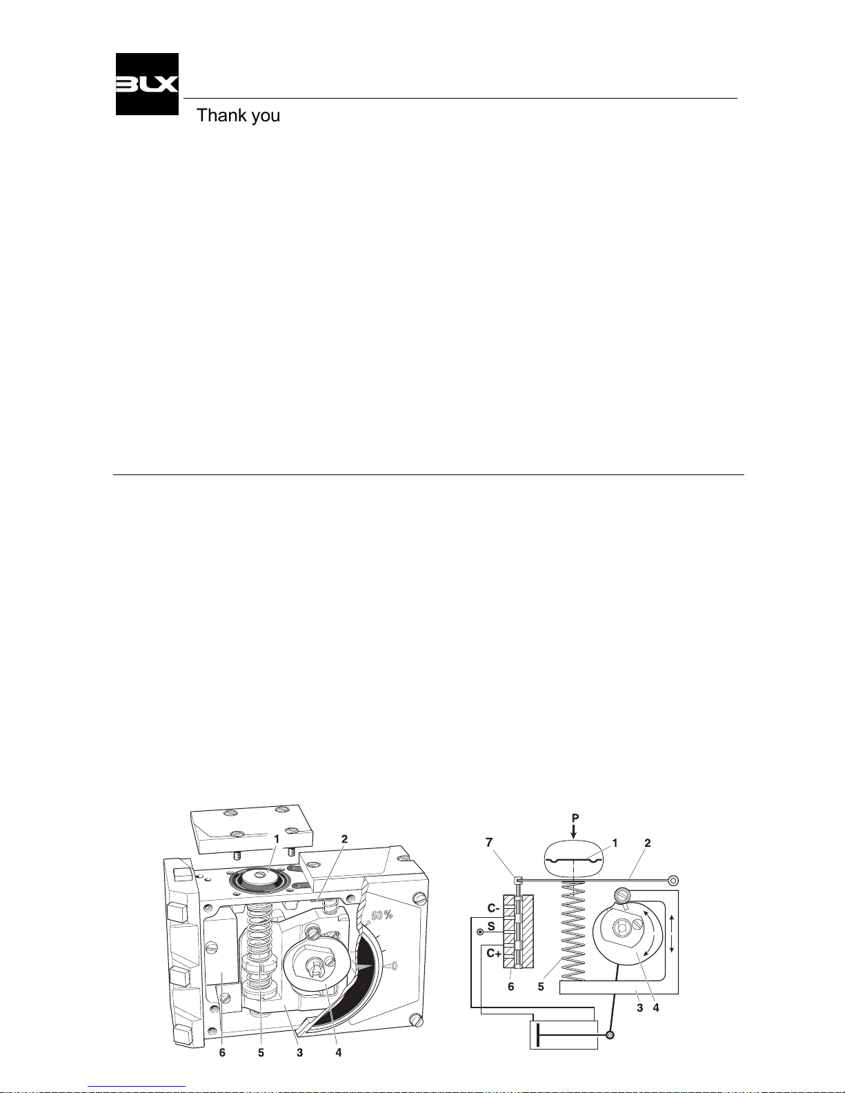
The V100 utilizes the force balance principal of
operation.
The desired value, in the form of pressure, affects
the membrane(1) with the force that is created
transferred to the balance arm(2).
The opposing force, which represents the actual
value, is provided by the feedback spring(5) and
works in the opposite direction on the balance
arm(2).
The feedback spring, resting on the guide arm(3),
is positioned by the shape and response of the
cam.
The cam(4) is connected to the cylinder’s (actuator) piston rod via the drive.
BLX V100 corrosion resistant painting and sealing
meet NEMA 4X as well as the sealing requirement
IP 66.
BLX V100 is furnished standard with four connecttions for gauges and a threaded opening for venting
the positioner’s exhaust.
The BLX R100 feedback unit for the V100 is
offered as an accessory (see separate manual).
1. INTRODUCTION
1.1 General.
BLX V100 is a compact, modular positioner for both
rotary and linear actuators, double or single acting.
There are two basic types:
V100P for a pneumatic signal and
V100E for a current signal.
BLX V100 has independent zero and span
adjustments, making calibration very simple.
External access for zeroing is standard.
The pilot valve(6) is connected to the balance arm
and follows the balance arm’s movement.
The system is stable when the spool(7) is in the
neutral position and the forces that affect the
balance arm is in equilibrium.
As soon as a signal change or a change in the
position of the piston rod occurs, the force balance
is also changed and the spool moves. Air immediately begins to flow into the part of the cylinder
(C+ or C-) which allows the feedback mechanism
to return the spool to the neutral position.
The system is self-stabilizing and searches for
equilibrium.
2
V100 Positioner
Page 5
12
1.4 Air quality recommendations
Poor air quality is one of the causes of premature
functional problems with pneumatic and electropneumatic equipment. The pilot valve and I/Pconverter are precision instruments and are therefore the most sensitive parts of the positioner.
a) Water in the supply air is a natural occurrence.
This happens when air is compressed. The compression heats the air and the natural degree of
water in the air can remain as moisture.
When the air cools in pipes etc. the moisture
condenses and becomes liquid water.
Large quantities can build and sometimes flood
small water separators. This excess water will
eventually reach the control valve and positioner.
This can cause corrosion damage to the I/P converter, causing the unit to malfunction.
We strongly recommend the use of water separators with adequate capacity. Coalesing filters from a
reputable manufacturer is an inexpensive way to
help prevent unit malfunctions or failures and add
life to the product. These filters remove particles
and moisture from air lines.
1.3 Product identification
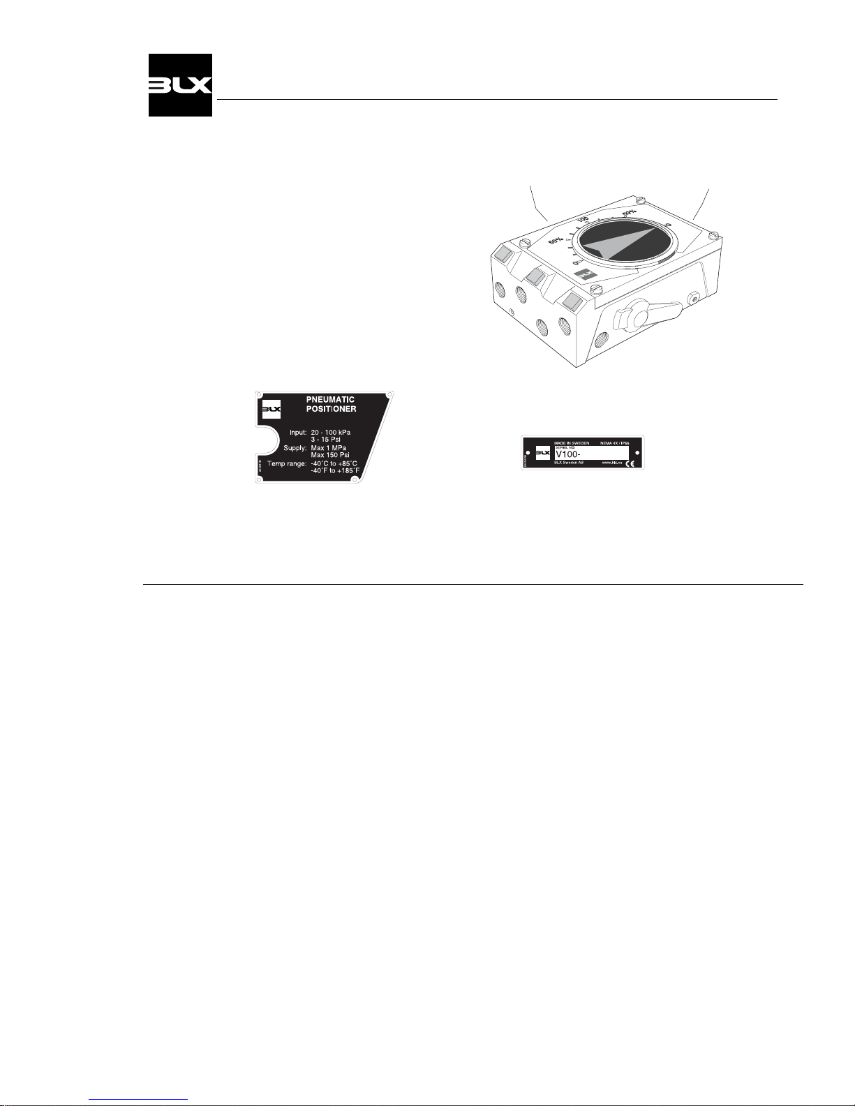
The V100 has two identification tags, the serial
number tag(1), and the product model tag(2).
The latter contains information on control
signal, maximum working pressure and temperature ranges.
Other information can be shown depending on
the model.
b) Oil in the supply air usually is from the main compressor. Oil can clog the small nozzles and disturb
the flapper in the I/P-converter. It can also cause the
spool to “drag” within the pilot valve.
The result is poor control or in the worst case, failure.
c) Particles in the air usually occur because of corrosion. Dirt and particles can block the small nozzles of
the I/P-converter. They can also cause the pilot valve
to malfunction. The unit may completely fail.
To ensure normal operational safety with BLX positioner products, we recommend that a water separator
and a <80 micrometer filter are mounted as close to
the product as possible.
If larger amount of oil is present an oil separator
should be installed as well.
To further increase operational safety, we recommend
that the working air is clean, dry and free of moisture,
water, oil, particles and other contaminants, in accordance with the international standard ISA S7.3-81.
The serial number tagThe product model
tag for V100P
3
V100 Positioner
Page 6
1.5 Safety Instructions
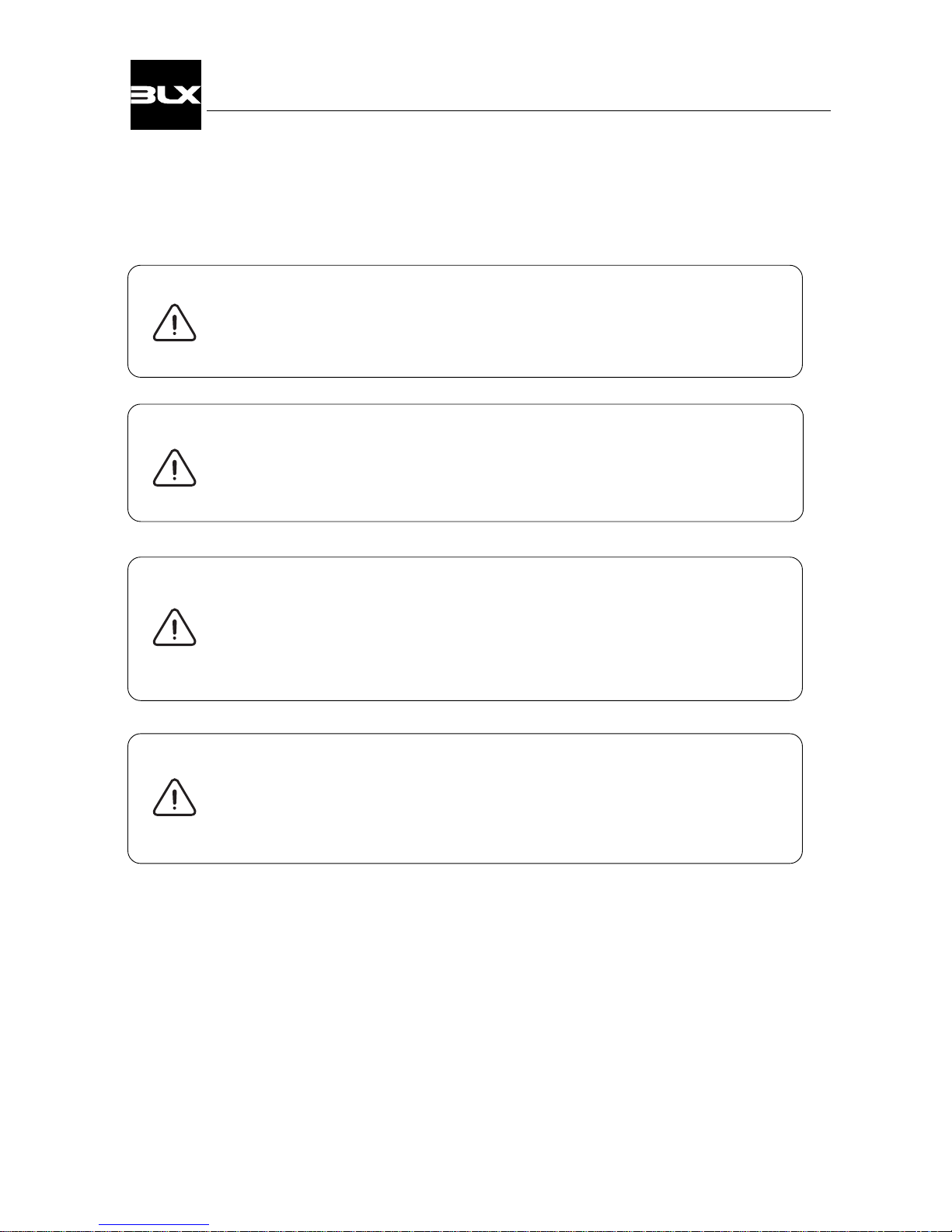
CAUTION: Beware of moving parts when positioner is operated!
CAUTION: Beware of parts with live voltage!
A voltage, which is normally not dangerous, is supplied to the positioner.
Avoid touching live parts and bare wires as well as short circuting live parts
and the housing.
CAUTION: Do not dismantle a pressurized positioner!
Dismantling a pressurized positioner will result in uncontrolled pressure release.
Always isolate the relevant part of the pipeline.
Release the pressure from the positioner and the piping.
Failure to do this may result in damage or personal injury.
CAUTION: Do not exceed the positioner performance limitations!
Exceeding the limitations marked on the positioner may cause damage to
the positioner, actuator and valve.
Damage or personal injury may result.
4
V100 Positioner
Page 7
2. INSTALLATION
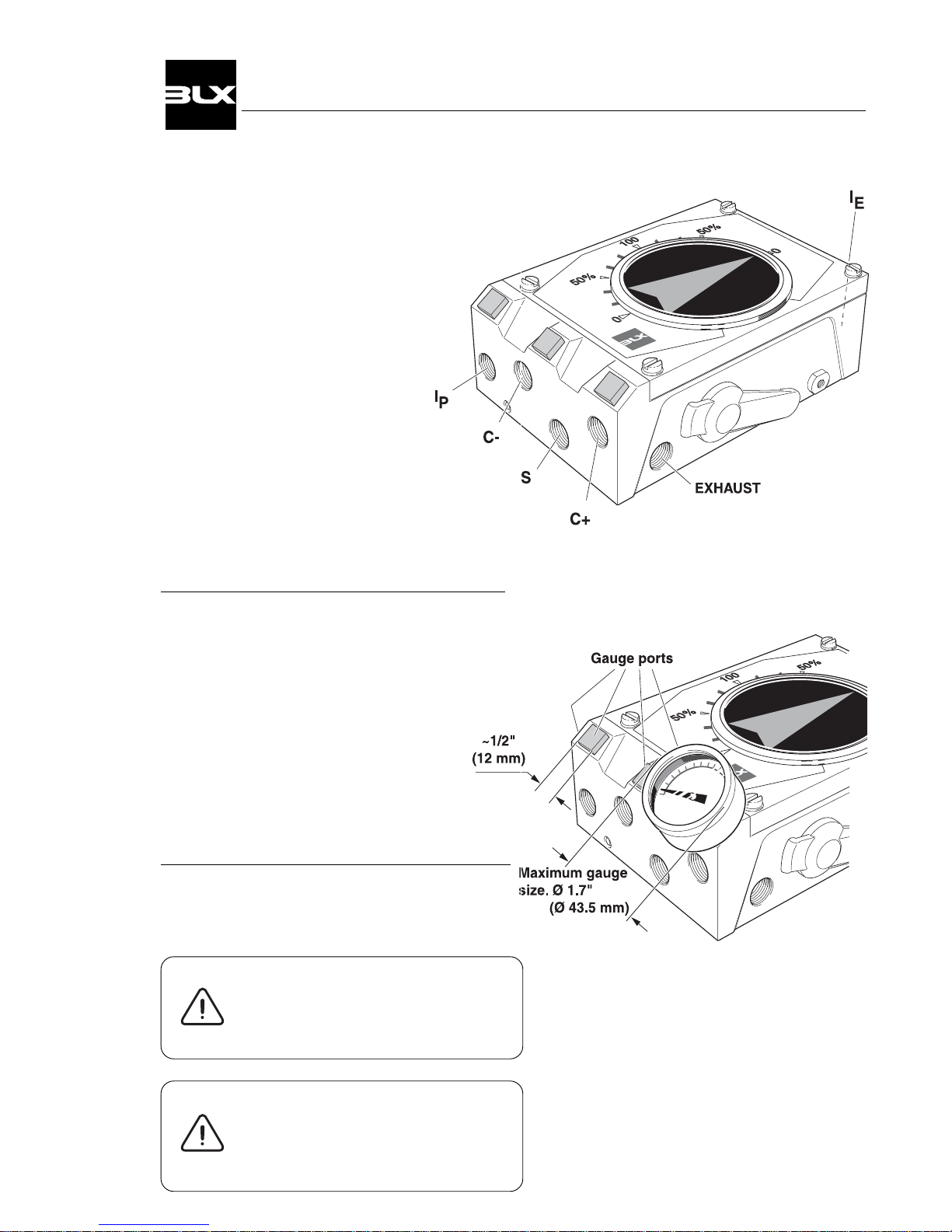
2.1 Connections
S – Supply air
V100P: max. 145 PSI / 1 MPa
V100E: 23 - 145 PSI / 0,15 -1 MPa
I
P
– Input, pressure signal
V100P: 3-15 PSI / 20-100 kPa
V100E: Plugged
IE – Input, current signal
V100E: 4-20 mA (Ri max 250 ohm)
V100P: Plugged
C+ - Cylinder connection + stroke
C- - Cylinder connection – stroke
EXHAUST - All air from the cylinder, I/P and
positioner is vented through this port.
Air connections
for male 1/4" NPT or G 1/4".
Gauge connections
for male 1/8" NPT or G 1/8".
Cable entry
for male 1/2" NPT, PG 13.5
or M20 cable fitting.
The appropriate threads are clearly indicated by
the markings on the housing.
Gauge ports I , C+ , C- and S are factory
plugged. Remove the plugs and replace with
gauges.
Liquid sealant for threads,
Loctite or similar, is recommended for all air connections.
The I
P
connection must
be plugged in V100E
The IE connection should
be plugged in V100P
5
V100 Positioner
Page 8
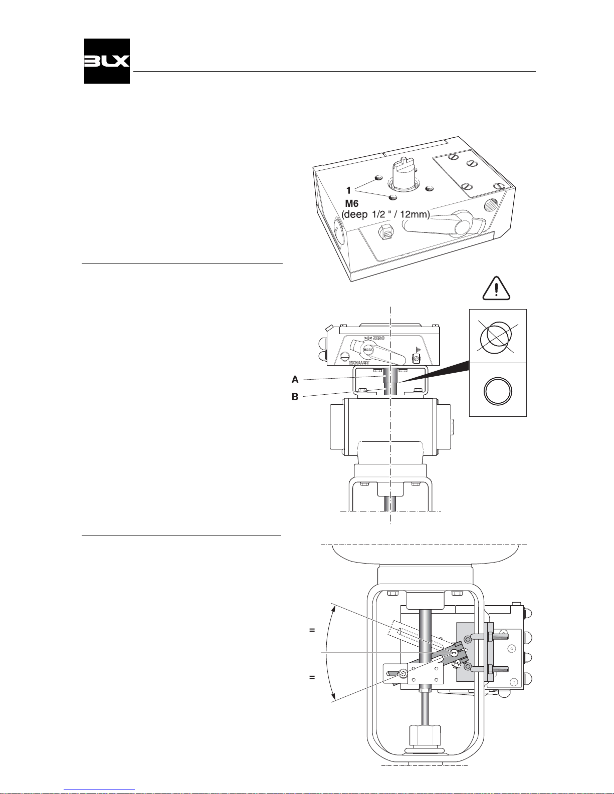
2.2 General mounting instructions.
The V100 has the ISO F05 hole pattern(1)
for mounting kits.
2.2.1 Rotary actuator
The BLX V100 has a very stable and properly sized drive shaft bearing.
However, the positioner drive(A) should
be aligned properly to the rotary actuator
spindle(B). A relatively small error combined with a rigid coupling can create
very
powerful radial forces, which can in turn
overload and in short time wear out even
the very best drive shaft bearing.
2.2.2 Linear actuator
When mounting on linear actuators, the
positioner should be attached in such a
way that its drive is in the center of the
actuator’s stroke. Proper installation and
alignment will minimize linearity error.
6
V100 Positioner
Page 9
A
B
D
C
E
F
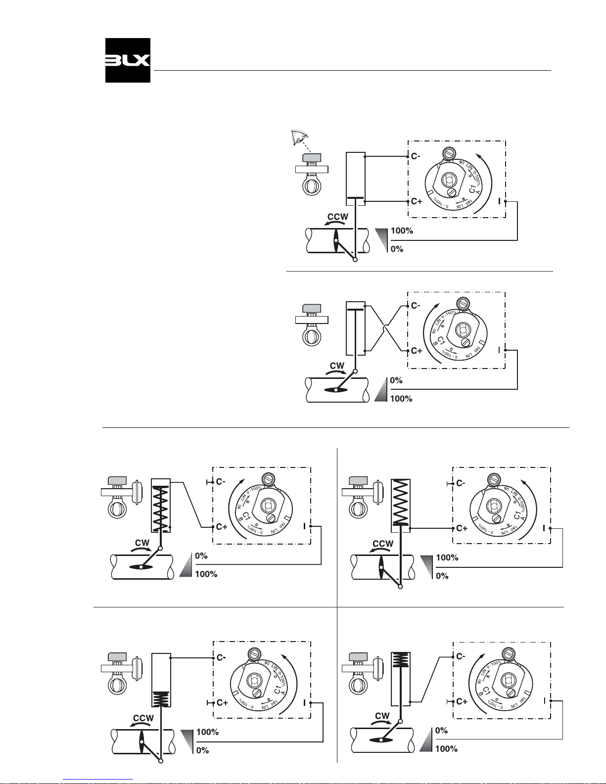
2.3 Installation instructions for rotary actuators
2.3.2 Single acting
2.3.1 Double acting
Signal closes
Signal opens
Direct (CCW)
Reverse (CW)
Spring closes Direct (CCW)Spring opens Reverse (CW)
Signal closes
Signal opens
Spring opens Direct (CCW) Spring closes Reverse (CW)
Signal opens
Signal closes
7
V100 Positioner
Page 10
G
H
I
J
K
L
N
M
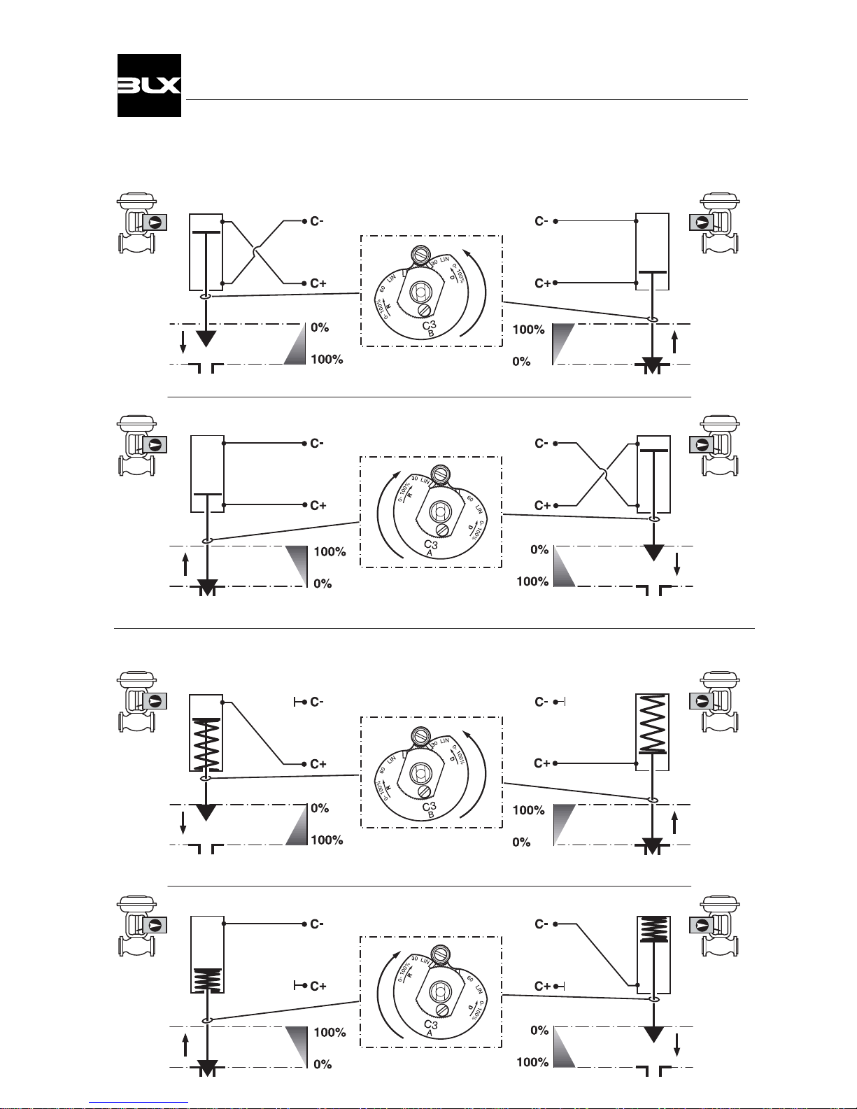
Signal opens Signal closes
2.4 Installation instructions for linear actuators
2.4.1 Double acting
Direct (CCW)
Signal closes Signal opens
Reverse (CW)
2.4.2 Single acting
Spring opens Spring closes
Direct (CCW)
Spring opens Spring closes
Reverse (CW)
Signal opens Signal closes
Signal closes Signal opens
8
V100 Positioner
Page 11
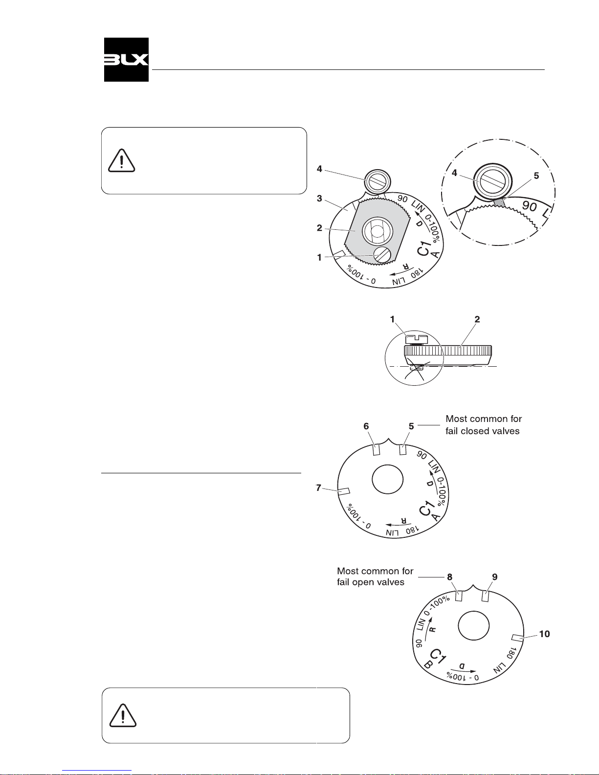
2.5 Cam
The V100 is standard shipped
with the C1-cam, factory set
for 90° ±1°, direct (CCW) turning.
2.5.1 Adjustments
Remove the front cover and indicator.
(see page 12)
1. Loosen the lock screw(1) and the cam
nut(2).
2. Run the valve/actuator to the stop/end
position at 0% input.
3. Turn the cam(3) so that the index mark(5)
for the selected curve aligns with the ball
bearing(4).
4. Tighten the cam nut by hand(2).
Check that the lock screw(1) is still loose.
(if not, loosen the lock screw slightly and
tighten the nut again)
5. Tighten the lock screw(1).
2.5.2 Cam specifications C1
Index mark / Starting point of rotation *
5. 90° Linear 0-100% CCW
6. 180° Linear 0-100% CW
6. 90° Linear 0-50% CW split range
7. 90° Linear 50-100% CW split range
8. 90° Linear 0-100% CW
9. 180° Linear 0-100% CCW
9. 90° Linear 0-50% CCW split range
10. 90° Linear 50-100% CCW split range
*Increasing signal rotation
Most valves rotate CW to close / CCW to open
9
When field reversing action of positioner
tubing must be reversed as well.
(see page 7 and 8)
V100 Positioner
Page 12
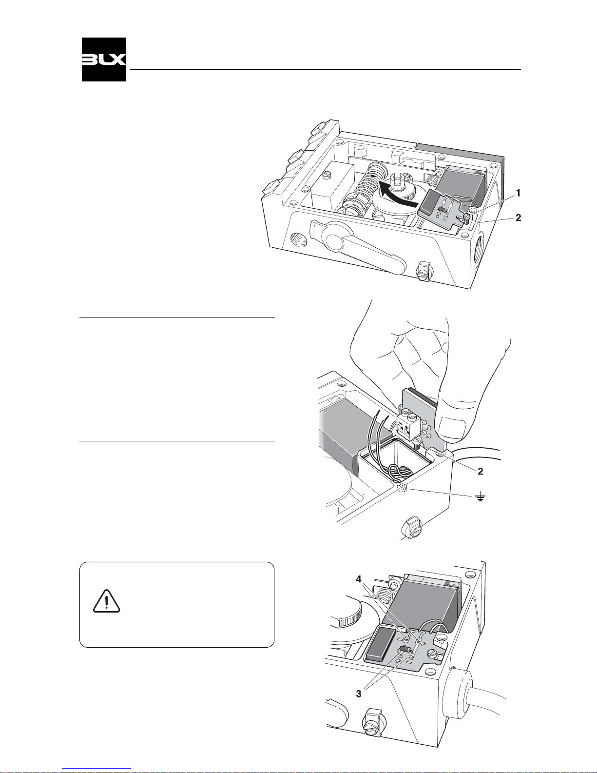
2.6 4-20 mA connection
2.6.1 Connecting the control signal
Remove the front cover and indicator.
(see page 12)
Loosen the screw(1) enough so that
the connection card can be lifted.
Secure the connection card into
the small slot(2).
Terminal block screws are now easily
accessible.
Connect the cables to its respective pole.
Max cable area 2,5 mm2, ~AWG 13
2.6.2 Checking the control signal
The control signal can be checked
without having to break the signal loop.
This is done by connecting a low ohmic
ampere meter over the test points(3).
2.6.3 Bench test with the calibrator
When bench testing, it is possible to
connect the control signal over the
points(4) without having to loosen
the connection card.
The I/P-converter is factoryadjusted. No extra range or
zeroing adjustments are
necessary.
10
V100 Positioner
Page 13
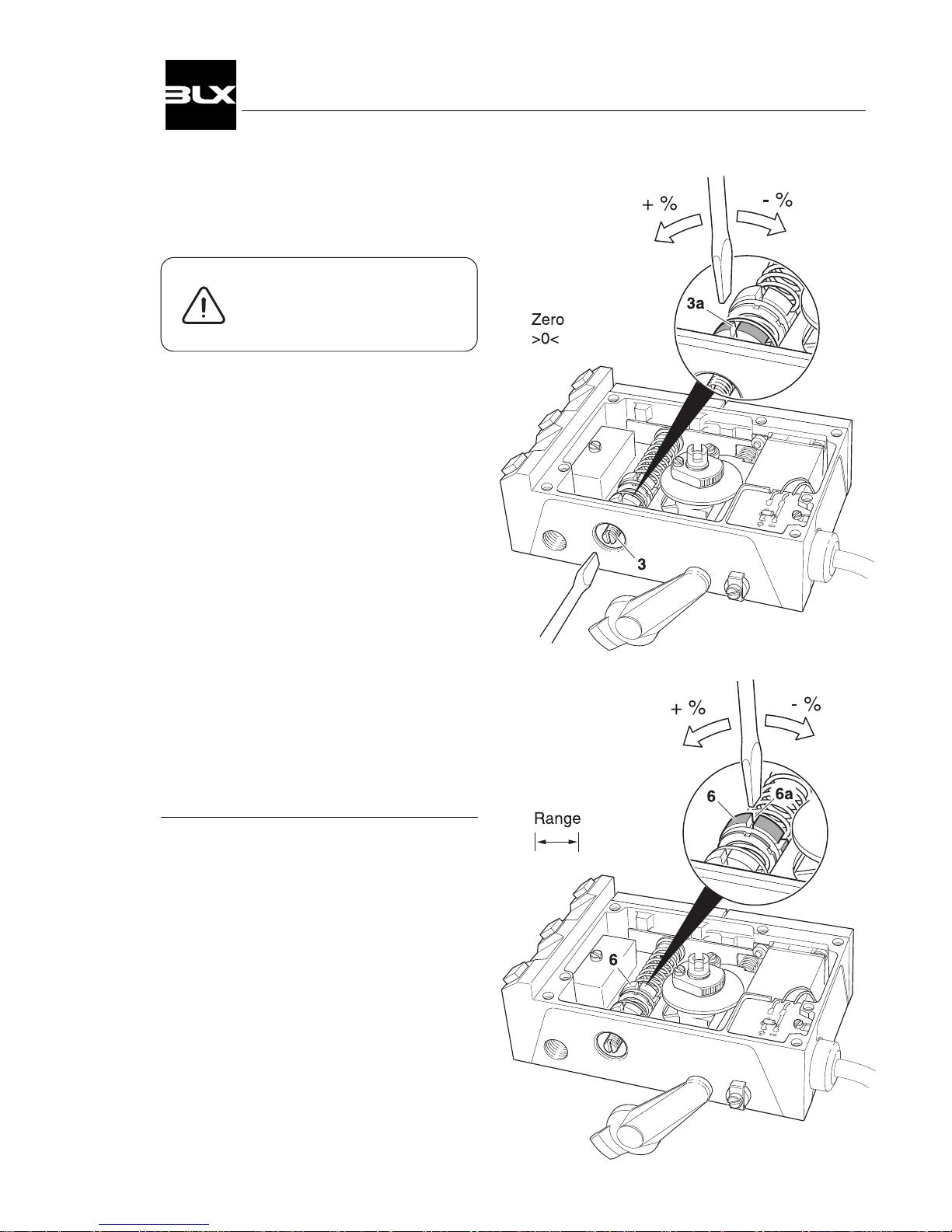
2.7 Calibration
The V100 is delivered factory
calibrated 0-100 % ±1%.
Calibration procedure
Zero position
1. Set 0% input signal.
2. Wait until the valve has adjusted.
3. Adjust the zero position by turning
the zeroing screw(3), with a screwdriver from the outside or by using
a slot(3a) on the yellow wheel.
Range
4. Increase to 100% input signal.
5. Wait until the valve has adjusted.
6. Adjust the range by turning the red
range nut(6).
Check the zero position
Make fine adjustments if necessary.*
* With Split Range, where zeroing can be
done by a signal other than 0%, the
steps
1-6 must be repeated until the desired
setting has been reached.
11
V100 Positioner
Page 14
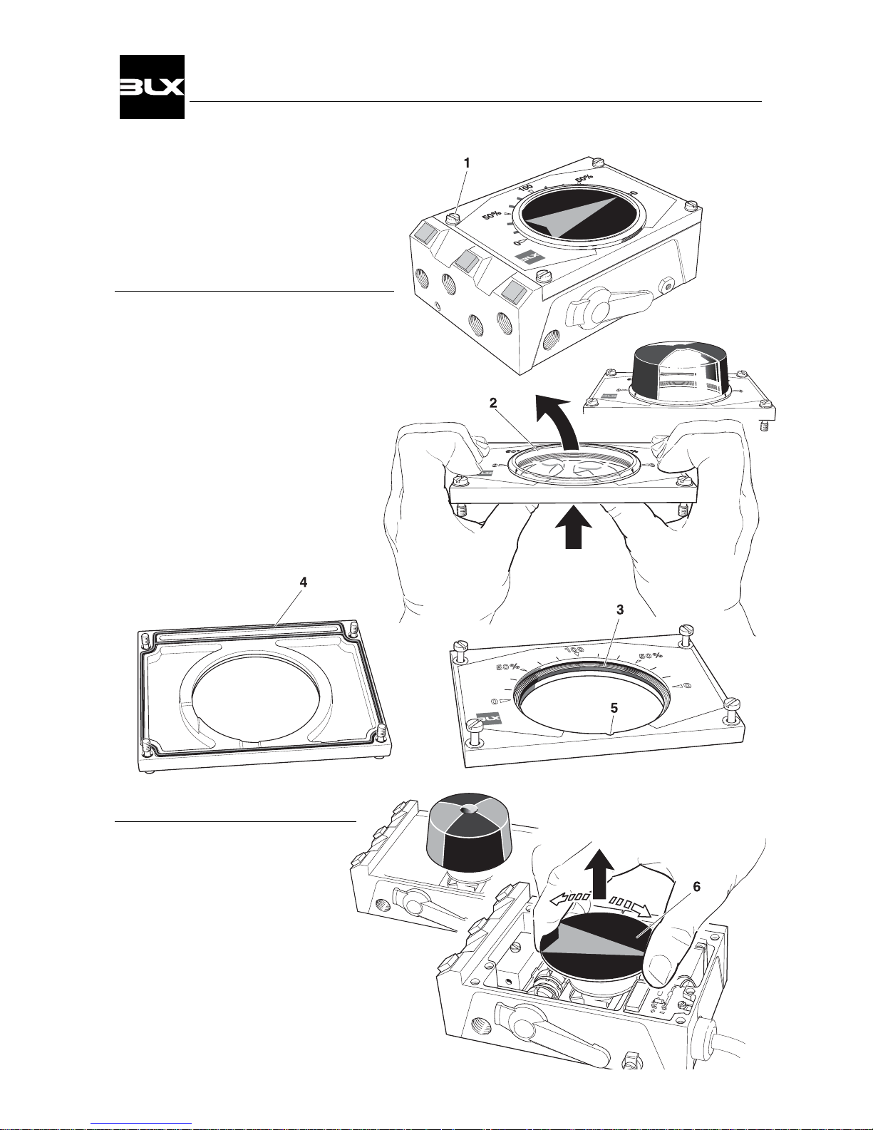
3. MAINTENANCE
3.1 Front cover and Indicator
Removing the front cover
Remove the four screws(1) and
the front cover.
Changing the sealing in the front cover
Remove the indicator cover(2) by pressing
from the backside.(see sketch)
Remove the rubber gasket(3) and replace
with a new gasket.
Remove the O-ring(4) on the backside
of the front cover and replace with a
new O-ring.
Mount the indicator cover by installing
its tap into the groove(5) of the front
cover and lock it in place.
Removing the indicator
Pull the indicator(6) straight up.
Important Note!
Note the indicator’s position so it
can be remounted in the same position.
Mounting the indicator
Install the indicator in place over the drive shaft
and press it straight down.
Turn the indicator to the proper display position.
12
V100 Positioner
Page 15
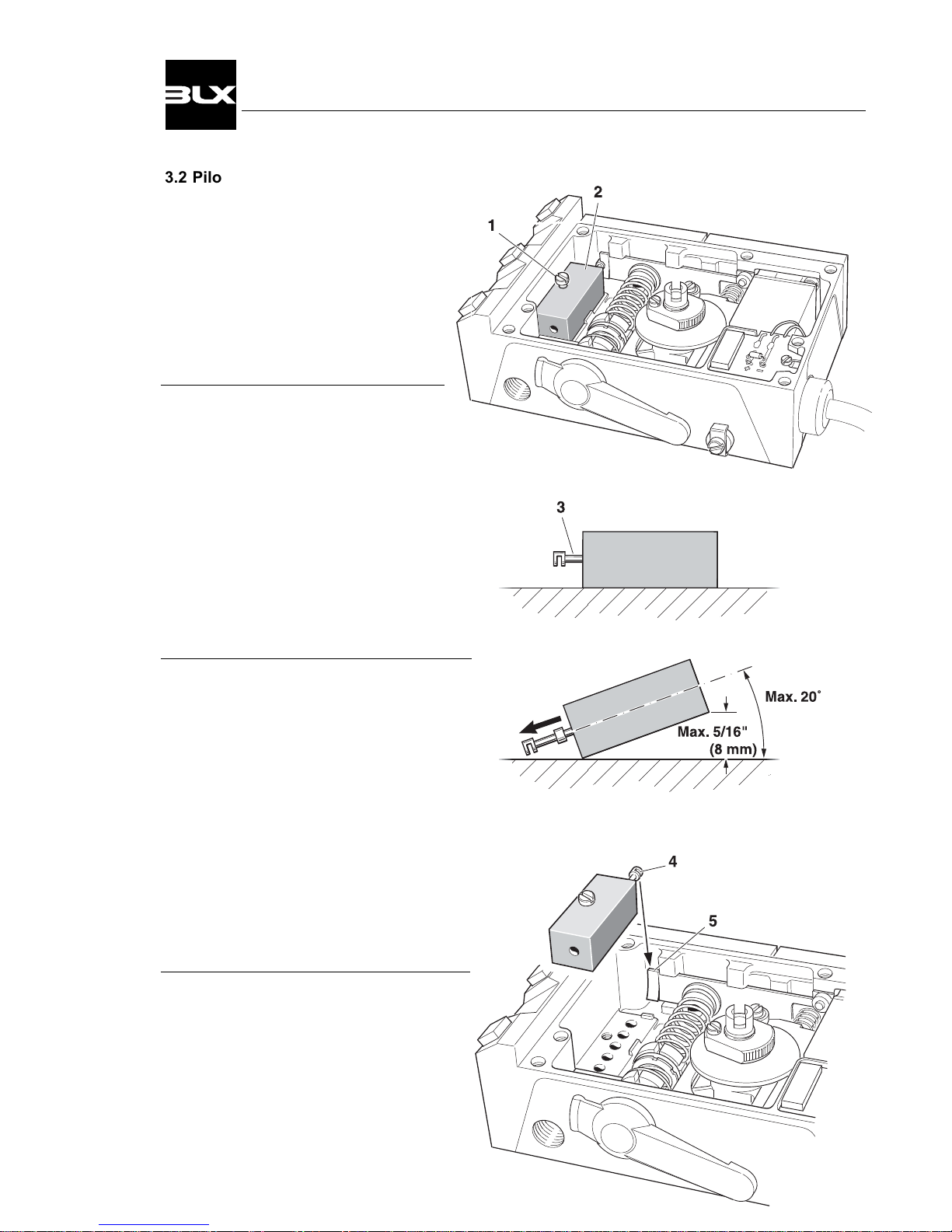
3.2 Pilot valve
Removal
Remove the front cover and indicator.
(see page 12)
Loosen the pilot retaining screw(1).
Lift the pilot valve(2) straight up.
Cleaning
Remove the spool(3) from the valve
housing.
Clean the parts with a soft cloth and
pipe cleaner using alcohol, acetone
or something similar.
Blow dry with clean, pressurized air.
Install the spool back in the valve
housing.
Check
Place the spool in its ”working position”.
(all four pistons inside the housing)
Slowly lift the pilot valve in one end.
The spool should start to glide before
the angle exceeds 20°.(see sketch)
If any of the parts show signs of wear,
we recommend replacing with a new
pilot valve assembly.
The pilot valve’s parts are matched
to attain the best possible performance. Mixing of parts can result in high
excessive bleed and/or poor function.
Install Pilot
Check the pilot valve’s O-rings.
Be sure that the spool’s ”gap”(4) fits over
the balance arm(5) and place the valve
straight down into place.
Tighten the retaining screw(1).
13
V100 Positioner
Page 16
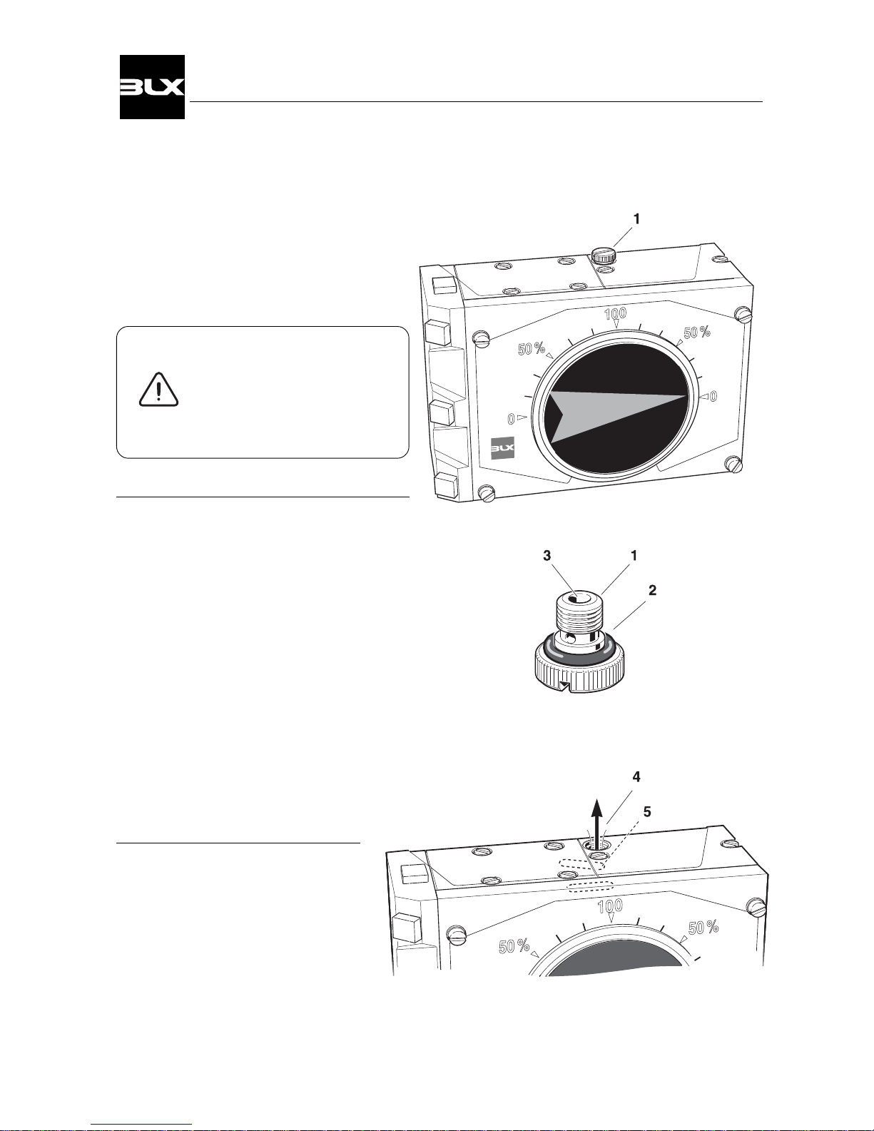
3.3 I/P-converter, type E1A
Cleaning the restrictor nozzle
The nozzle(1) can be removed for cleaning
with the supply air on.
Use caution when removing
the nozzle in that the air
pressure may cause the
nozzle to ”shoot out” from
the unit.
We recommend alcohol, acetone or something similar for cleaning the nozzle.
Blow dry with pressurized air.
Avoid inserting improper objects in the
small hole(3) Ø 0.0079" (Ø 0.2mm).
If necessary, a cleaning needle, Ø 0.0060-
0.0079" (Ø 0.15-0.20mm) can, with caution,
be used.
Also check the O-ring(2) and replace if it
is necessary.
Filter check
Air should pass (hiss) through the
hole(4) with the air on.
If no air exhausts, it could mean that
the filter (5) is completely clogged and
needs to be replaced. (see page 15)
14
V100 Positioner
Page 17
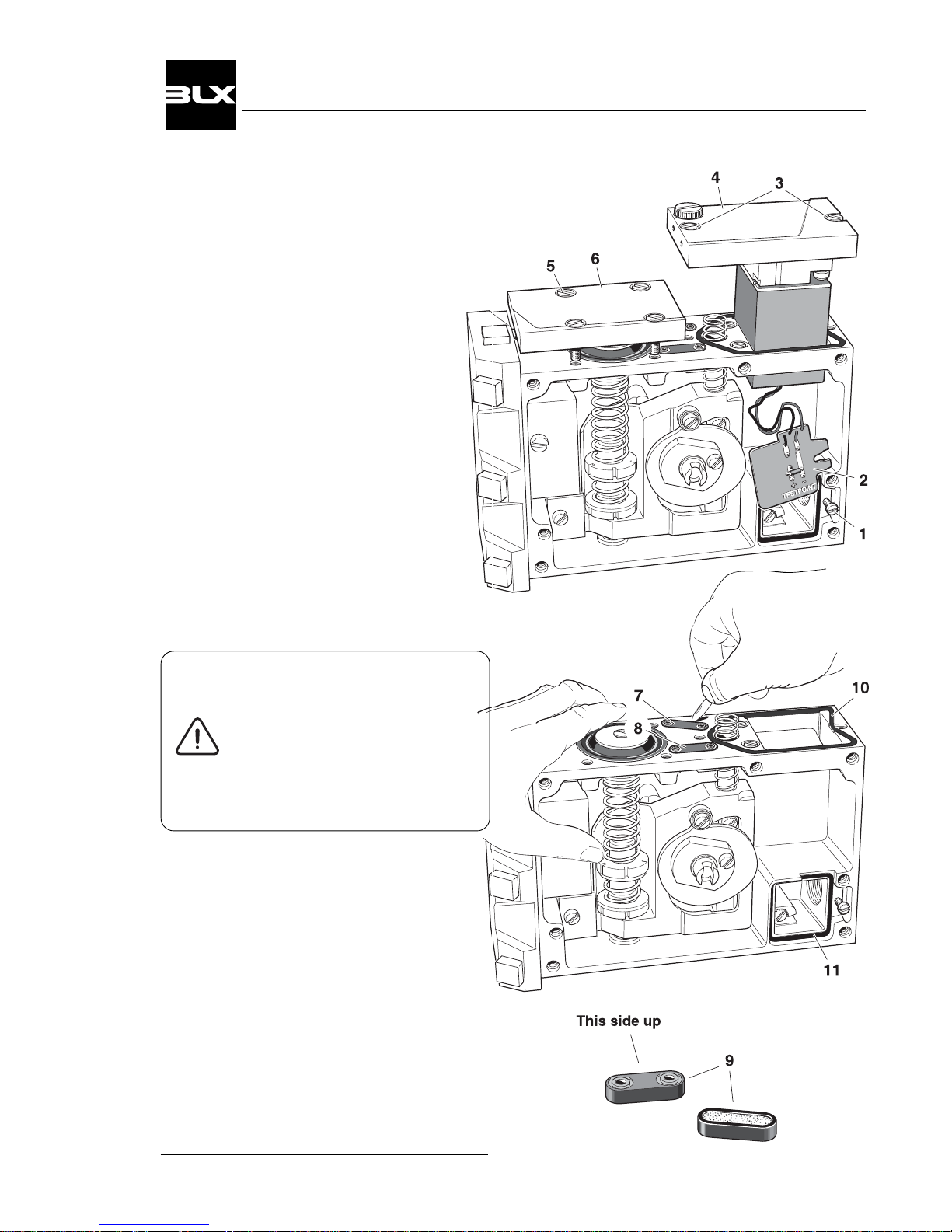
3.4 Filter
Changing the filter
1. Remove the front cover and indicator.
(See page 12)
2. Loosen the screw(1) and lift out the card.
3. Loosen the screws(3) and lift out
the I/P-converter.
4. Loosen the screws(5) and remove
the membrane cover(6).
Please Note!
Be sure that the O-ring in the
cover(6) is not removed.
5. Cautiously remove the filter cap(7 & 8)
with a sharp pointed object e.g.
a pocket knife.
6. Remove the filter(9) from its rubber
envelope.
If the filter(9) shows traces of oil
or water, check the water/ oil
separator in the supply line.
Oil and water can cause
functional problems in
the I/P-converter.
7. Insert the new filter in the rubber enve-
lope.
8. Press the filter caps(9) into the housing.
To make installation in the housing easier,
a small amount of grease or oil can be
applied to the rubber.
9. Install the other parts in reverse order.
Please Note!
Also check the seals.(10 & 11)
Replace if they are damaged.
15
V100 Positioner
Page 18
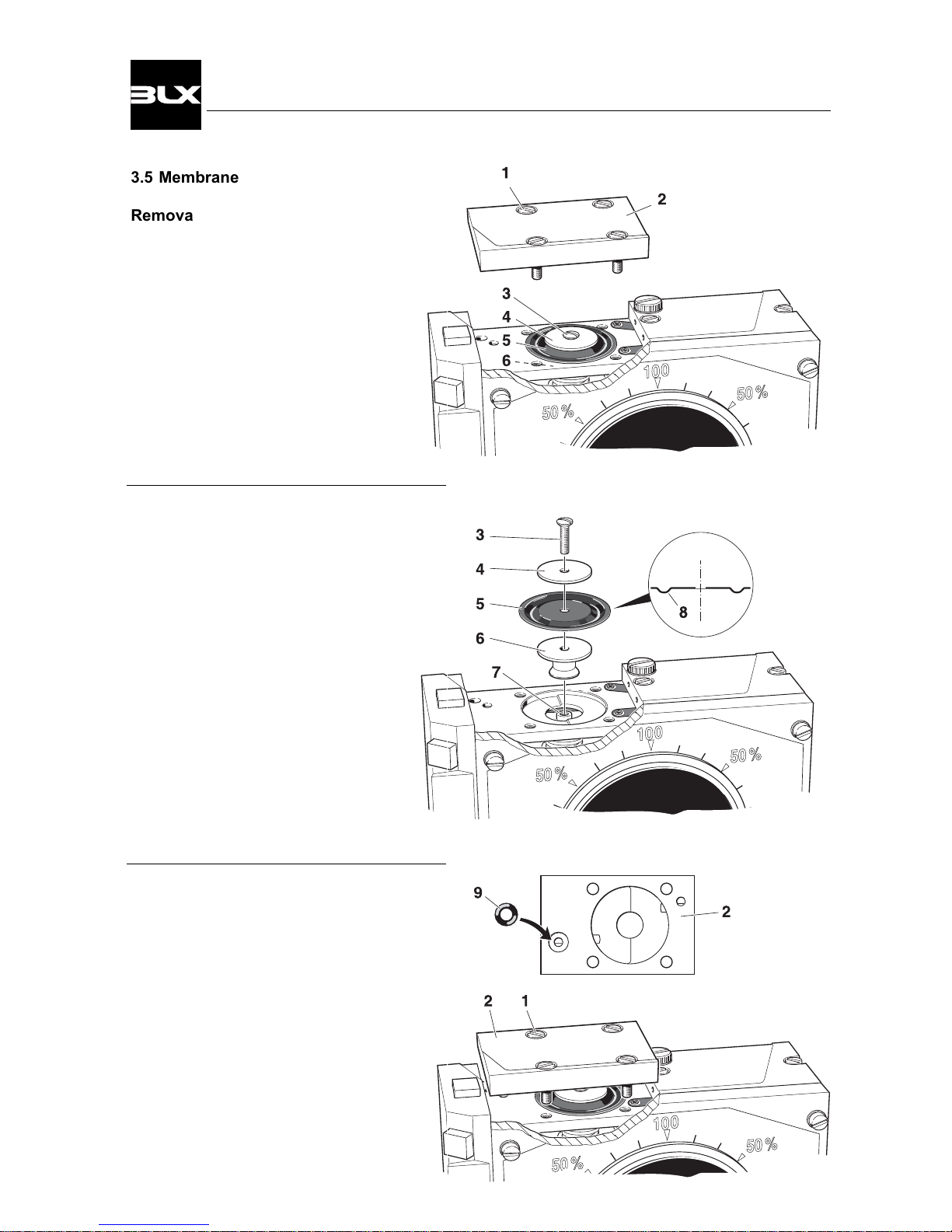
3.5 Membrane
Removal
Loosen the screws(1) and remove
the membrane cover(2). Be cautious
of the O-ring in the membrane cover.
Loosen the screw(3).
Remove the washer(4), membrane(5)
and membrane piston(6).
Mounting the membrane
Install the membrane piston(6) over
the cylindrical dowel(7).
Place the membrane(5), with the
bulge(8) hanging down towards the
membrane piston(6).
Place the washer(4) on top, put the
screw(3) in the hole and turn it tightly.
Mounting the membrane cover
Check that the O-ring(9) is not damaged.
Install the membrane cover(2) and tighten
the screws(1) crosswise.
16
V100 Positioner
Page 19
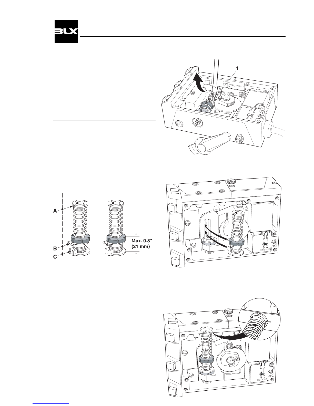
3.6 Feedback spring, changing
Removal
The feedback spring(1) can be removed
by inserting a screwdriver between the
upper spring coils and compressing it so
that the upper spring socket is released
from its seat.
Mounting
Before the feedback spring is replaced, a
basic adjustment must be performed.
The A, B, and C gaps must be aligned.
The distance between the lower edge of
the lower spring support and the upper
edge of the red range nut must be less
than 0.8" / 21mm before mounting.
Fit the ”gaps” B and C into the slots on the
guided arm and at the same time install the
lower spring support on the yellow zeroing
wheel.
Compress the spring and flex it into the
housing, securing the upper spring socket
onto the stud on the balance arm.
Be sure that the upper spring socket and
lower spring support lies flat with their respective contact surfaces and that the red
range nut can be turned.
17
V100 Positioner
Page 20
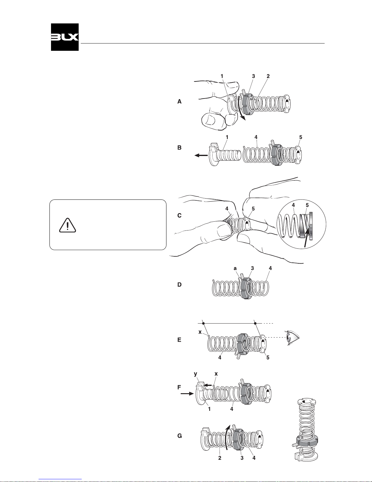
3.7 Feedback spring
Disassembling
A.Remove the spring support(1) from the
red range nut(3).
B.Disassemble the spring support(1) and
the spring(4).
C.Hold the spring socket(5) and try to
push the spring off the socket by
pressing a screwdriver or similar
against the end of the spring.
(see sketch).
Please Note!
The spring is self-locking
to the socket and may
be very secure.
Reassembling
D.Thread the range nut(3), with the friction
spring(a) side first, onto the spring(4).
E.Screw the upper spring socket(5) into
the spring(4). The spring is self-locking
on the socket and should sit very tight.
Turn the spring on to the socket as
much as possible.
Note! One of the four grooves in the
upper spring socket(5)must align
with the dowel pin(x) on the spring.
F. Install the spring dowel(x) into the
crotch(y) in the spring support(1).
G. Thread the range nut(3) onto the
screw(2). If this is difficult, it may help
to compress the spring(4) slightly.
18
V100 Positioner
Page 21
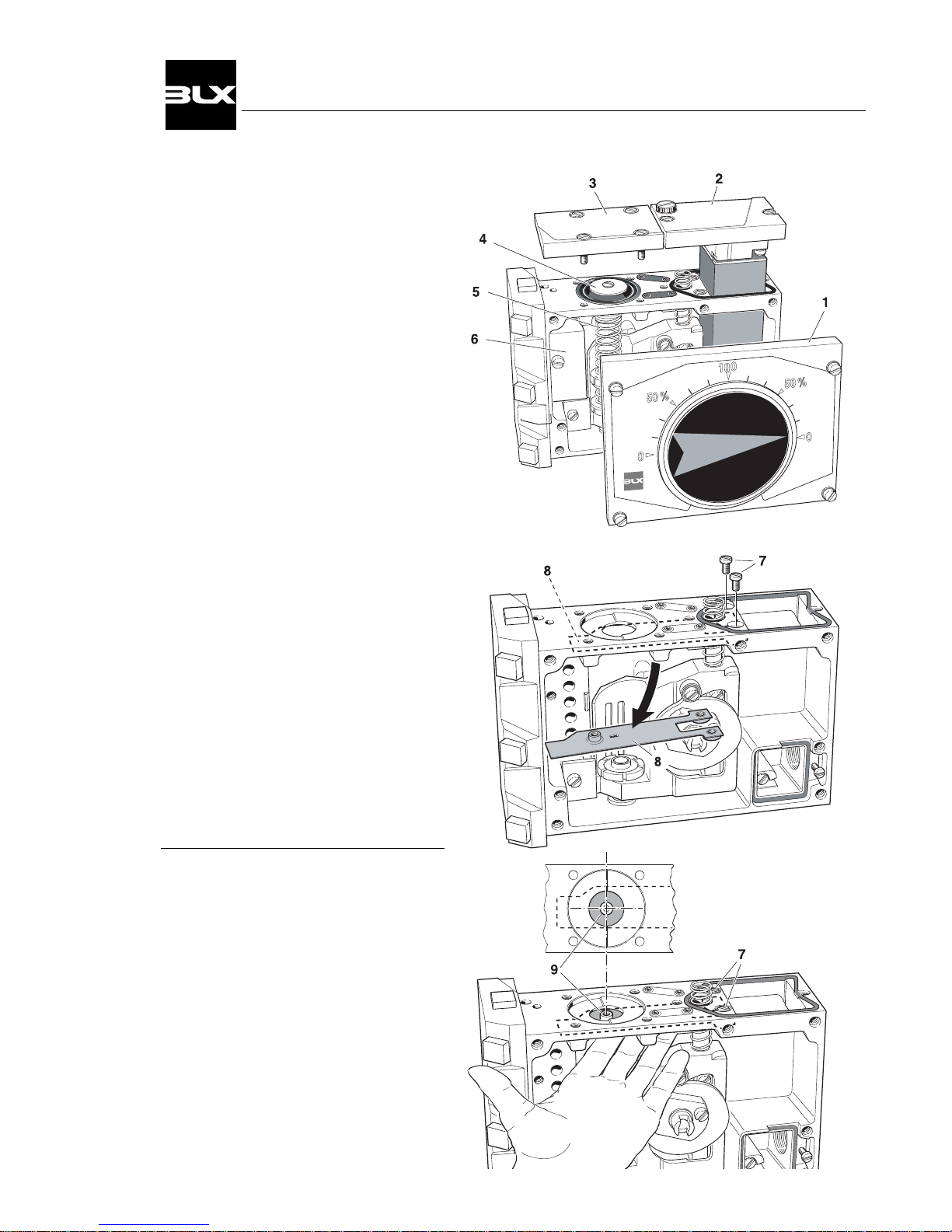
3.8 Balance arm
Removal
Before the balance arm can be removed, the front cover(1), I/P-converter or
cover(2), membrane cover(3), membrane(4), feedback spring(5) and pilot
valve(6) must all be removed.
Loosen the screws(7) and remove the
balance arm(8).
Mounting
Install the balance arm into the housing.
Center the dowel(9) with the hole in the
housing.
Tighten the screws(7) and check the
centering.
Install the remaining parts according to
their respective instructions.
19
V100 Positioner
Page 22
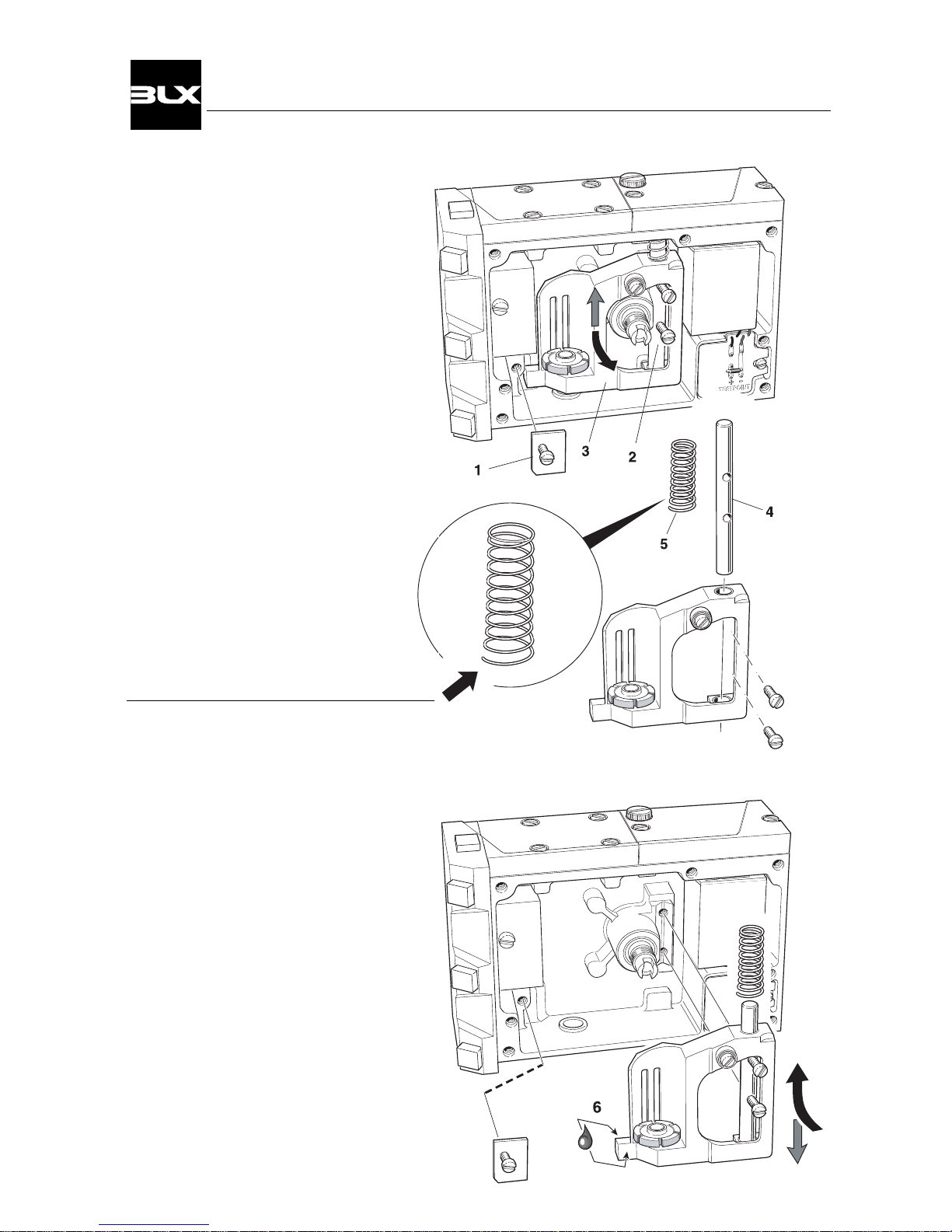
3.9 Guide arm, changing
Removal
Before the guide arm can be removed,
the feedback spring (see page 17) and
cam (see page 9) has to be removed.
Remove the stop washer(1).
Loosen the screws(2) and remove the
arm(3) together with the guide pin(4)
and spring(5).
Mounting
Insert the guide pin(4) into the bearings of
the arm.
Install the spring(5) on to the upper end of
the guide pin with the larger end towards
the arm.
Secure the guided arm with the guide pin
into the V-block.
Tighten the two screws(2).
Apply a small amount of grease on the
arm support’s(6) sliding surfaces.
Mount the stop washer(1).
Make sure the arm moves freely.
20
V100 Positioner
Page 23
;;
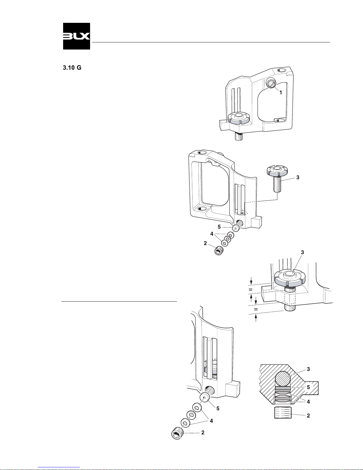
3.10 Guide arm, disassembly
Ball bearing, changing
Loosen the screw(1) and remove the ball
bearing.
Mount the new ball bearing with Loctite
in the M4-hole on the arm and tighten the
screw securely.
Zeroing screw, removal.
Loosen the socket set screw(2).
Remove the three spring washers(4) and
the friction block(5).
The friction block may be difficult to remove and doesn’t necessarily need to be
removed to be able to unscrew the zeroing
screw(3).
Mounting
Install the zeroing screw(3) to the middle
position.
Mount the friction block(5) and the spring
washers(4).
Screw in the socket set screw(2) tightly.
Loosen the screw 1/8 turn and check that
the zeroing screw has proper turning
friction.
21
V100 Positioner
Page 24
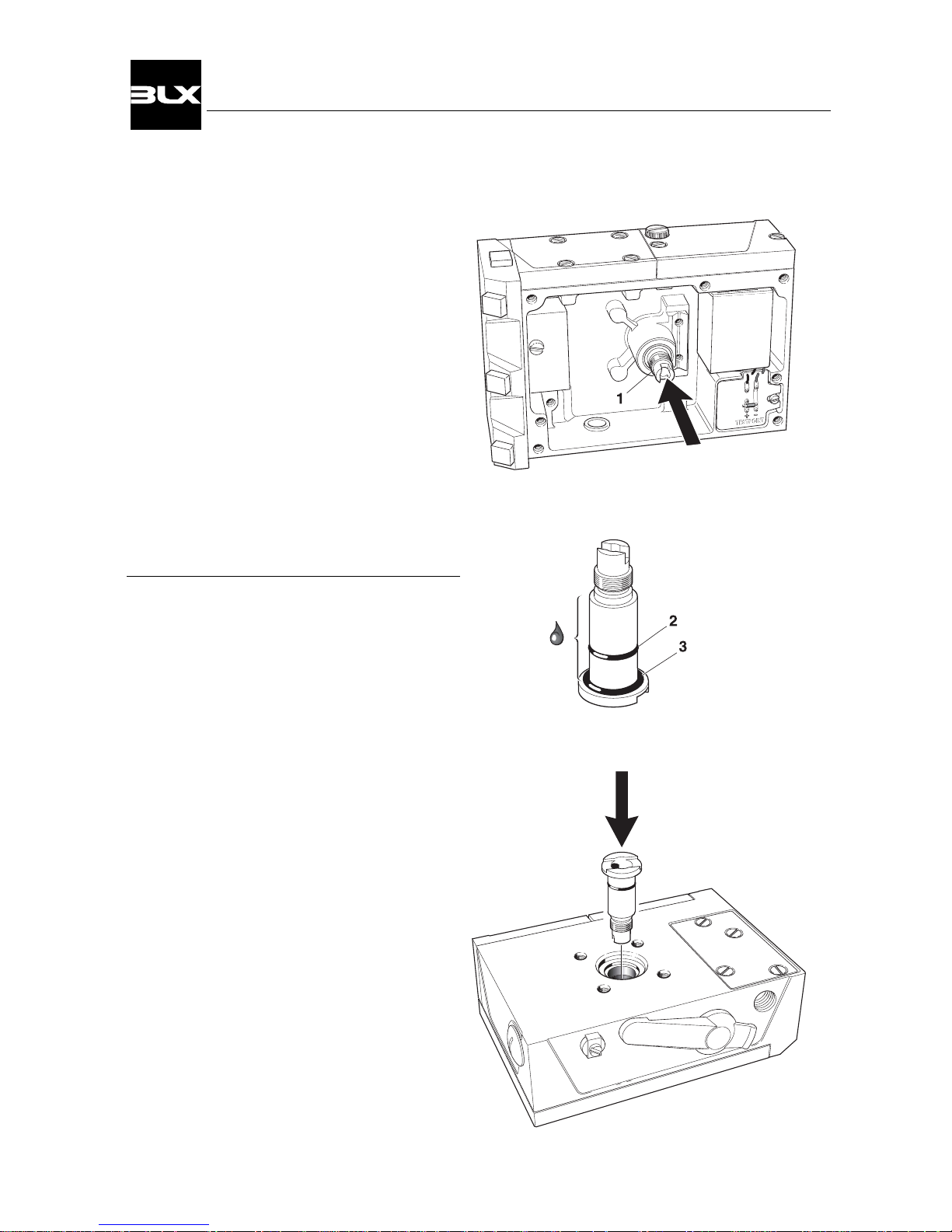
3.11 Drive shaft
Removal
Before the drive shaft can be loosened, the
cam must be removed.
Remove the drive shaft(1) by hand from
the inside. If necessary replace defective
O-rings(2 & 3).
Mounting
Apply a small amount of oil to the drive shaft’s
surface and O-rings.
Install the drive shaft and press into place.
22
V100 Positioner
Page 25
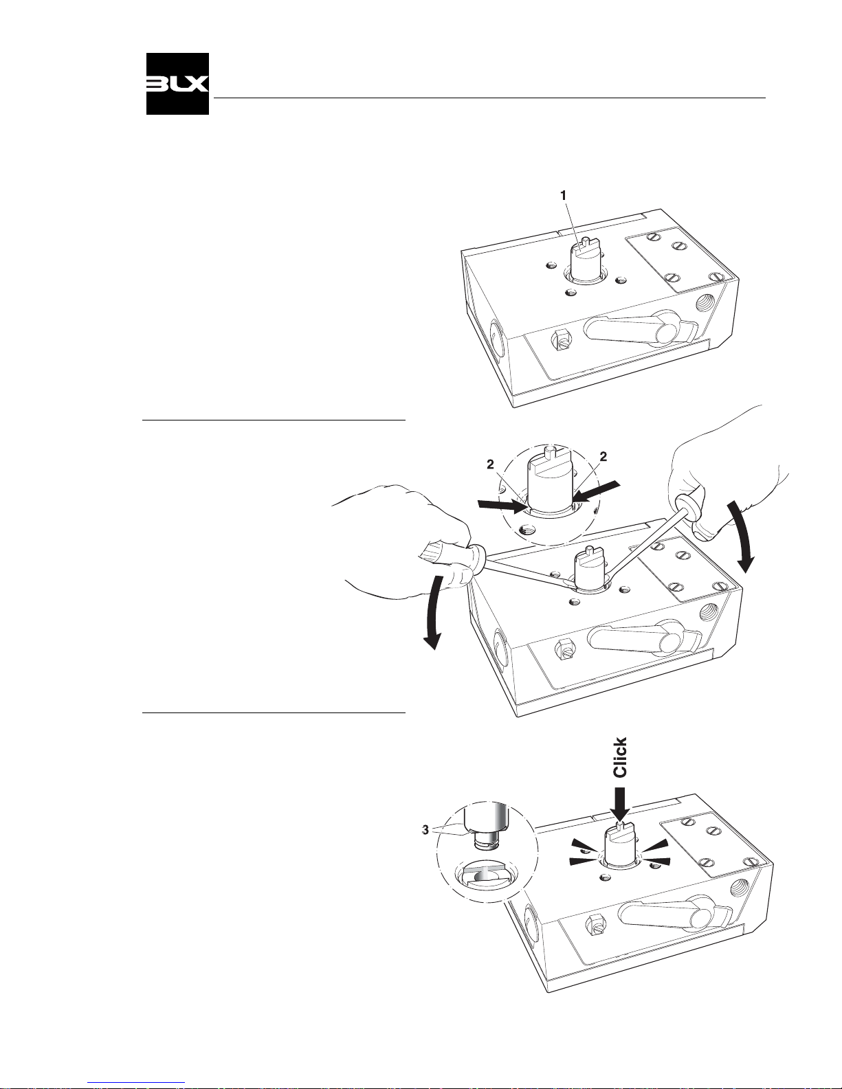
3.12 Drive
BLX offers a variety of drives(1), suitable
for the most frequently used actuator types.
Removal
“Pop out” the drive by prying
two screwdrivers, equally
under the edges(2) of
the drive, using the
housing as fulcrum.
Mounting
Press the drive down into the drive shaft
hole.
Turn the flats(3) into place and press down.
Check to see that the drive is set securely in place.
23
V100 Positioner
Page 26
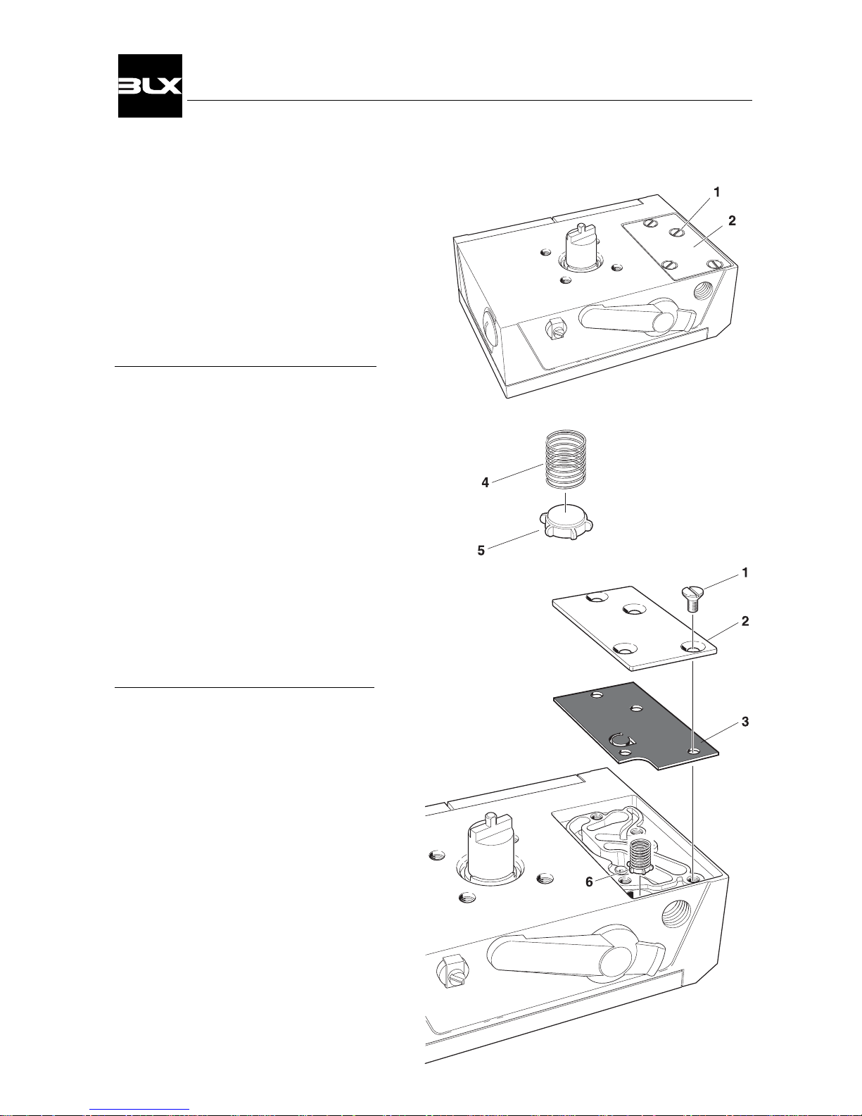
3.13 Safety valve
Removal
Loosen the screws(1).
Remove the tightening cover(2) and the
gasket(3).
Lift out the safety valve(6).
Safety valve, assembly
The safety valve is designed with a weak
spring(4) and a rubber plug(5).
For proper functioning, the spring and the
rubber plug need to be mounted together.
The spring turns firmly on the rubber
plug’s cylindrical section.
Mounting
Install the safety valve(6) with the rubber
plug facing the housing.
Insert the gasket(3) and the tightening
cover(2).
Mount the screws(1).
24
V100 Positioner
Page 27
1
2
3
4
8
5
6
9
10
7
7
4. CONVERTING
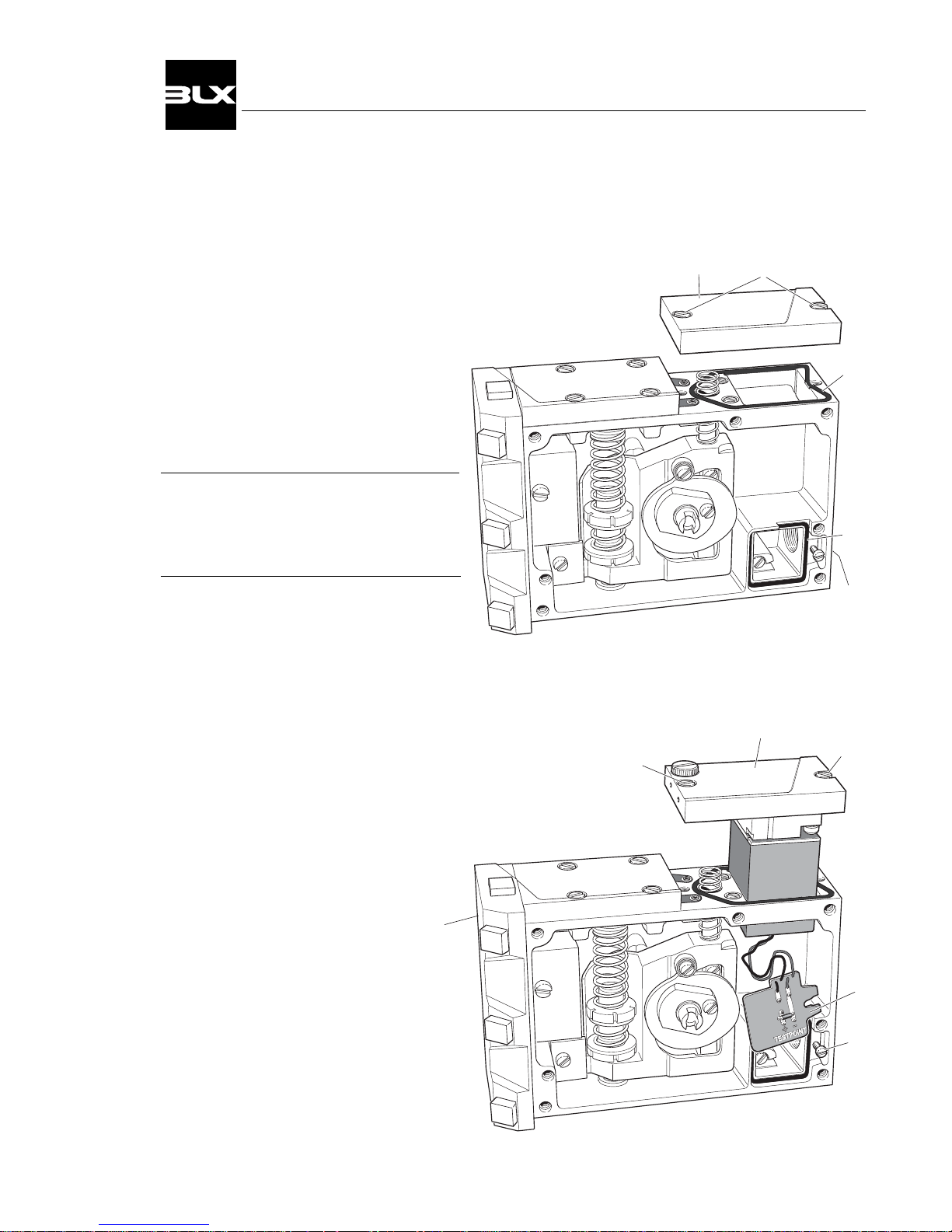
4.1 Converting from V100P to V100E
1. Remove the front cover and indicator.
(see page 12)
2. Loosen the screws(1) and remove the
cover(2).
3. Unscrew the protective plug from the
IE -connection(8).
Please Note!
Check the seals(3 & 4).
Replace if they are damaged.
4. Insert the connection card(5) and the I/Pconverter(6) through the square hole in
the housing.
5. Secure the I/P-converter with the screws(7).
6. Install the connection card in its seat and
secure with the locking screw(10).
7. Plug the port(9) marked IP.
Threading requirements G 1/4" or 1/4" NPT
is indicated by the markings on the housing.
8. Connect the control signal (see page 10).
25
V100 Positioner
Page 28
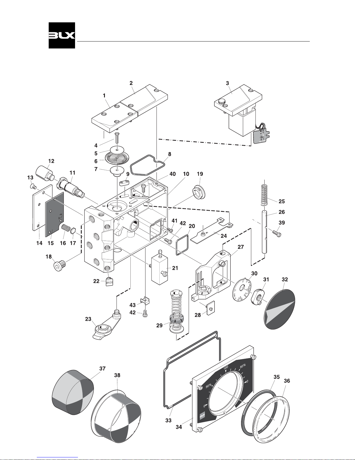
5. SPARE PARTS
5.1 Exploded drawing
26
V100 Positioner
Page 29

5.2 Spare parts list
Item Description Part no Qty
1 ..... Membrane cover ................................. 10066 ............. 1
Screw MCS 5x14-5 SS ........................ ............. 4
- Mylar washer..................................... 10095 ............. 4
- O-ring Ø 5x2 NBR ............................. ............. 1
2 ..... Cover plate .......................................... 10061 ............. 1 (V100P only)
- Screw MCS 5x14-5 SS ..................... ............. 1
- Screw MCS 5x12-5 SS ..................... ............. 1
- Mylar washer..................................... 10095 ............. 2
3 ..... I/P-converter EA1................................ 10160 ........... 1 (V100E only)
- Restictor nozzle ................................ 10047 ............. 1
- Connection card ................................ 10012 ............. 1
- Screw MCS 5x14-5 SS ..................... ............. 1
- Screw MCS 5x12-5 SS ..................... ............. 1
- Mylar washer..................................... 10095 ............. 2
4 ..... Screw MKFS 4x14 SS ......................... ............. 1
5 ..... Membrane washer .............................. 10019 ............. 1
6 ..... Membrane ........................................... 10035 ............. 1
7 ..... Membrane piston ................................. 10018 ............. 1
8 ..... O-ring Ø54x2.5 NBR ........................... ............. 1
9 ..... Filter cap ............................................. 20030 ............. 2
- Rubber channel nitrile ....................... 10008 ............. 1
- Filter .................................................. 10092 ............. 1
10 ..... Housing ...............................................
Bearing 15x8 ....................................... ............. 2
11 ..... Drive shaft ........................................... 10022 ............. 1
- O-ring Ø15x2 NBR ............................ ............. 1
- O-ring Ø12x1.5 NBR ......................... ............. 1
12 ..... Drive* .................................................. ............. 1
- Spring circlip ..................................... 10079 ............. 1
13 ..... Screw MFS 5x8 SS ............................. ............. 4
14 ..... Tightening cover .................................. 10016 ............. 1
15 ..... Gasket nitrile ....................................... 10017 ............. 1
16 ..... Safety valve spring .............................. 10021 ............. 1
17 ..... Safety valve plug nitrile ........................ 10020 ............. 1
18 ..... Plug 1/4" S2610-1/4 ............................ ............. 1
19 ..... Blind plug NPT 1/2" ............................. 10026 ............. 1
Blind plug M20x1.5 .............................. 20032 ............. 1
Blind plug PG 13.5 ............................... 20033 ............. 1
- O-ring Ø 18.5x1.5 NBR ..................... ............. 1
20 ..... O-ring Ø 34x2 NBR ............................. ............. 1
21 ..... Pilot valve W1 ...................................... 10039 ............. 1
Pilot valve W2 ...................................... 10071 ............. 1
Pilot valve W3 (Standard) ................... 10090 ............. 1
- Screw MCS 5x25-5 SS ..................... ............. 1
- O-ring Ø 5x1.5 NBR * * ..................... ............. 5
- Valve gasket ...................................... 10093 ............. 1
22 ..... Gauge plug .......................................... 10048 ............. 4
23 ..... Zero plug nitrile .................................... 10005 ............. 1
24 ..... Balance arm ........................................ 10013 ............. 1
25 ..... Retainer spring .................................... 10075 ............. 1
26 ..... Guide pin ............................................. 10015 ............. 1
27 ..... Guided arm complete ........................... 10161 ........... 1
- Ball bearing ....................................... ............. 1
- Zero screw ........................................ 10091 ............. 1
- Screw MCS 4x10 SS ......................... ............. 1
- Bearing 8x8 ....................................... ............. 2
28 ..... Stop washer ........................................ 10014 ............. 1
- Screw MCS 4x8-4 SS ....................... ............. 1
29 ..... Feedback spring assembly .................. 10159 ........... 1
30 ..... Cam C1 (Std) * ................................... 10024 ............. 1
31 ..... Cam nut ............................................... 10023 ............. 1
- Screw MCS 4x8 SS ........................... ............. 1
32 ..... Indicator Arrow .................................... 10064 ............. 1
- Circlip SGA 15 SS ............................. ............. 1
33 ..... O-ring front cover nitrile ....................... 10072 ............. 1
34 ..... Front cover assembly .......................... 20031 ............. 1
- O-ring front cover nitrile ..................... 10072 ............. 1
- Front label 0-90-0° (Standard)* ......... 20006 ............. 1
- Screw MCS 5x20-5 SS ..................... ............. 4
- Mylar washer..................................... 10095 ............. 2
35 ..... Indicator gasket nitrile ......................... 10036 ............. 1
36 ..... Indicator cover flat ............................... 10000 ............. 1
37 ..... Indicator, raised ................................... 10063 ............. 1
- Circlip SGA 15 SS ......................... .... ............. 1
38 ..... Indicator cover Raised ......................... 10043 ............. 1
39 ..... Screw MCS 4x16 SS ........................... ............. 2
40 ..... Screw MCS 4x10 SS ........................... ............. 2
41 ..... Screw MCS 3x10 SS ........................... ............. 1
42 ..... Screw MSCS 4x8 SS .......................... ............. 2
43 ..... Grounding clamp ................................. 10067 ............. 1
*Cams with other ranges, Front labels with other scale readings and Drive’s suitable for the most frequently
used actuator types, are available.
**Only Spool valves marked: 10039-R0-WA1, 10071-R0-WA2, 10071-R1-WA2, 10090-R0-WA3
and 10090-R1-WA3
27
V100 Positioner
Page 30

6.1 Specifications
V100P V100E
Input range: 3-15 PSI (20-100kPa) 4-20 mA (Ri<250ohms)
Supply pressure: <145 PSI (<1MPa) 21.8-145 PSI (0.15-1MPa)
Linearity error: <0.7% f.s <1.0% f.s
Hysteresis: <0.4% f.s <0.6% f.s
Repeatability: <0.3% f.s <0.5% f.s
Pressure Gain:
@87 PSI (600kPa) 750 P
out
/ P
in
750 P
out
/ P
in
acc. to ISA S75.13 49 %P
out
/ %P
in
49 %P
out
/ %P
in
Air Capacity: SCFM (SLPM) SCFM (SLPM)
@29 PSI (200kPa) 9.5 (270) 9.5 (270)
@87 PSI (600kPa) 28.3 (800) 28.3 (800)
@145 PSI (1MPa) 47.1 (1350) 47.1 (1350)
Bleed Rate: SCFM (SLPM) SCFM (SLPM)
@29 PSI (200kPa) 0.18 (5) 0.2 (5.7)
@87 PSI (600kPa) 0.53 (15) 0.6 (17.0)
@145 PSI (1MPa) 0.88 (25) 1.0 (28.3)
Weight: 3.5 lbs (1.6kg) 3.8 lbs (1.7kg)
Weight with gauges: 4.0 lbs (1.8kg) 4.2 lbs (1.9kg)
Temp range: -40° to +185° Fahrenheit
-40° to +85° Celsius
Air connectors: 1/4” NPT (optional G threads)
Gauges: 1/8” NPT (optional G threads)
Cable entry: 1/2” NPT (optional M20x1.5 or PG 13.5)
Ingress & corrosion protection: NEMA 4X and IP66
Coating: Powder Polyester
Options: Feedback Spring for 6-30 PSI (40-200kPa) input signal.
Gauges.
Pilot Valves:
W1 Low Gain-Medium Flow-Low Bleed
for better stability and lower bleed.
Pressure gain @87 PSI =300
Bleeds approx. 33% < than W3
Air capacity =10% < W3 (above chart)
W2 High Gain-High Flow-High Bleed
For faster response and better accuracy.
Pressure gain @87 PSI >1000
Bleeds approx. 33% > than W3
Air capacity = W3 (above chart)
W3 Medium Gain-High Flow-Medium Bleed
For “average” capacity and bleed
Standard Pilot Assembly
Specifications shown in above chart
6. TECHNICAL INFO
28
V100 Positioner
Page 31
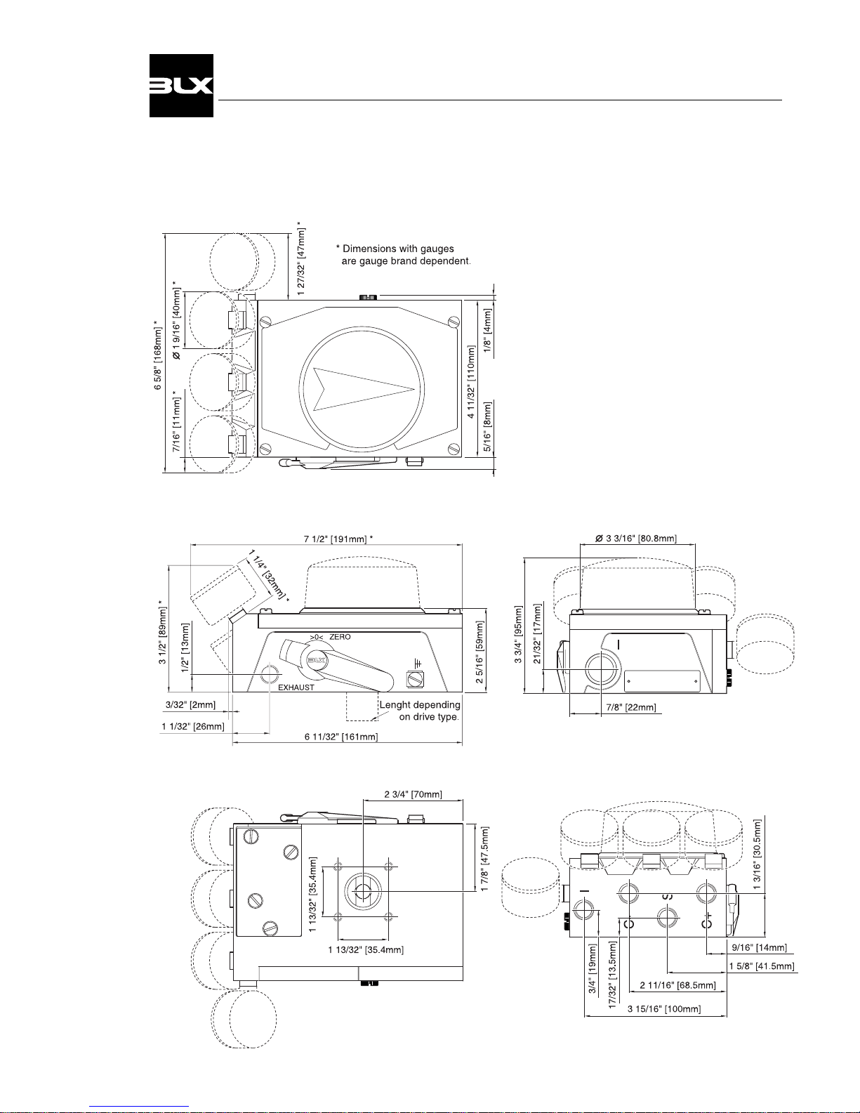
6.2 Dimensions
29
V100 Positioner
Page 32

 Loading...