

Page 1
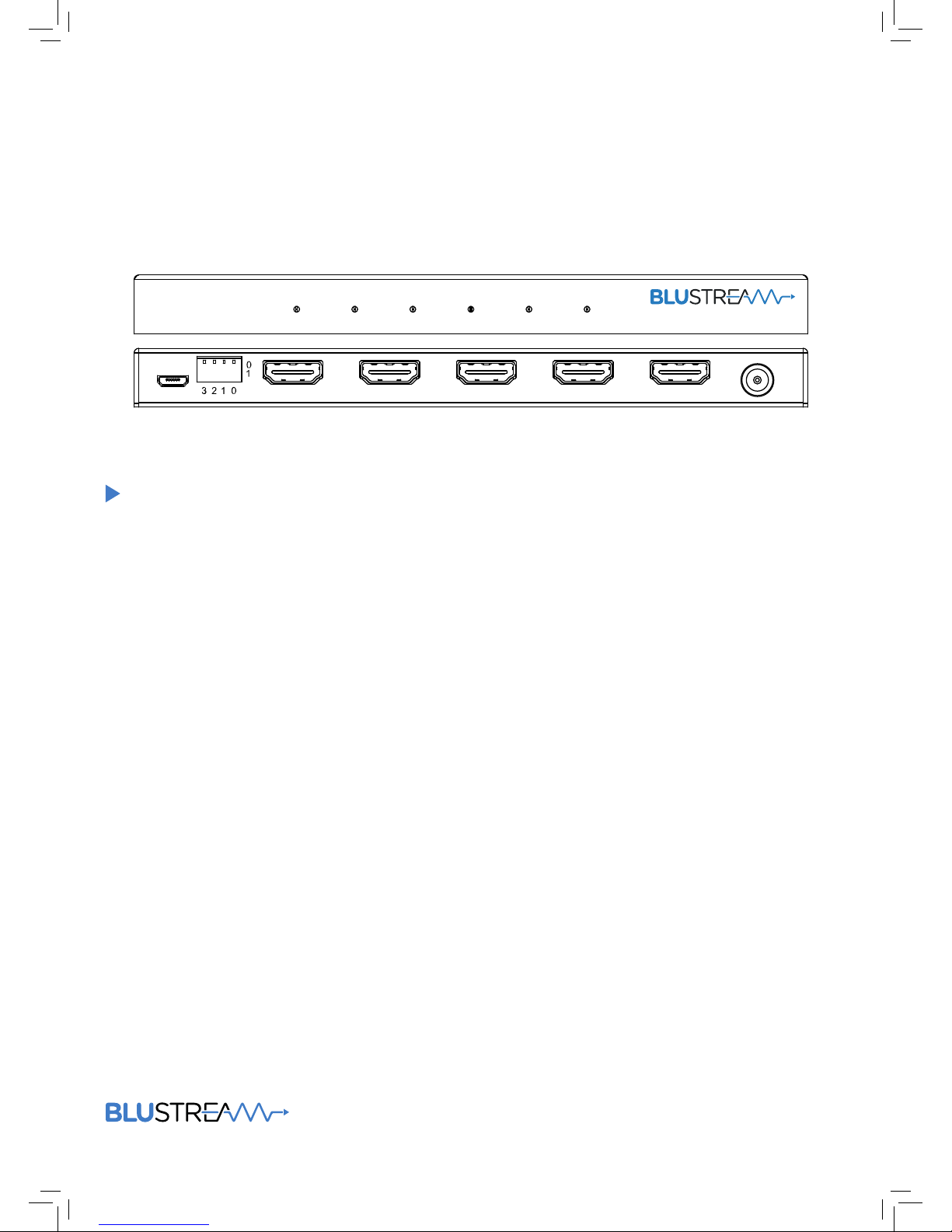
SP14-V2
User Manual
4-Way 4K HDMI 2.0 Splitter
Power Input Output 2Output 1
Output 4Output 3
Update
DC
5V
Input Output 2Output 1 Output 4Output 3
SP14 -V2
Page 2
SP14-V2 USER MANUAL
02
www.blustream.co.uk
Surge protection device
recommended
This product contains sensitive electrical components that may be damaged
by electrical spikes, surges, electric
shock, lightning strikes, etc. Use of
surge protection systems is highly
recommended in order to protect and
extend the life of your equipment.
Safety And
Performance Notice
Do not substitute or use any other
power supply other than the enclosed
unit, or a Blustream approved replacement.
Do not disassemble Blustream units
for any reason. Doing so will void the
manufacturer’s warranty.
Contents
Thank you for purchasing
this product.
For optimum performance and safety,
please read these instructions carefully before connecting, operating or
adjusting this product. Please keep this
manual for future reference.
Introduction 03
Features 03
Panel Descriptions 04
EDID Control 05
Application Diagram 06
Specifications 07
Package Contents 07
Maintenance 07
Page 3

SP14-V2 USER MANUAL
03
contact [email protected] / [email protected]
Our SP14-V2 4K HDMI 2.0 splitter distributes a single HDMI source to four
simultaneous outputs. The SP14-V2 splitter supports full HDMI 2.0 and HDCP 2.2 with
video resolutions up to and including 4K @ 60Hz 4:4:4.
Introduction
FEATURES:
• Features 1x HDMI input that is replicated to 4x HDMI outputs
• Supports full HDMI 2.0 specification 4K UHD video (4K @60Hz 4:4:4)
• HDCP 2.2 compliant
• Supports 3D signal display
• Supports all industry standard video resolutions including VGA-WUXGA and 480i-4K
• Supports all known HDMI audio formats including Dolby TrueHD, Dolby Atmos, Dolby Digital Plus and DTS-HD Master Audio
transmission
• Advanced EDID management
Page 4
SP14-V2 USER MANUAL
04
www.blustream.co.uk
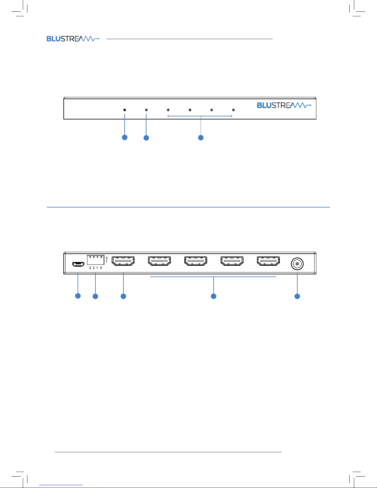
Front Panel
1 Power LED indicator – indicates if the SP14-V2 is powered on/o
2 Input LED indicator – Indicates if the HDMI source connected to the HDMI input is active
3 Output LED indicator – indicates if the display connected to the HDMI output is active
SP14-V2 Panel Description
4-Way 4K HDMI 2.0 Splitter
Power Input Output 2Output 1
Output 4Output 3
4-Way 4K HDMI 2.0 Splitter
Power Input Output 2Output 1
Output 4Output 3
Update
DC
5V
Input Output 2Output 1 Output 4Output 3
SP14 -V2
1
2
3
Front Panel
1 Micro USB Connector – Used to upgrade firmware of the SP14-V2
2 EDID DIP switch – Used to adjust HDMI input EDID settings
3 HDMI input – Connect HDMI source
4 HDMI outputs 1 to 4 – Connect HDMI outputs to displays
5 Power port – Use included 5V/2A DC adaptor to power the Splitter.
1
2 53
4
Page 5
SP14-V2 USER MANUAL
05
contact [email protected] / [email protected]
[DIP]=0000: HDMI EDID Copy (Pass-through)
[DIP]=0001: HDMI 1080p@60Hz, Audio 2CH PCM
[DIP]=0010: HDMI 1080p@60Hz, Audio 5.1CH PCM/DTS/DOLBY
[DIP]=0011: HDMI 1080p@60Hz, Audio 7.1CH PCM/DTS/DOLBY/HD
[DIP]=0100: HDMI 1080i@60Hz, Audio 2CH PCM
[DIP]=0101: HDMI 1080i@60Hz, Audio 5.1CH PCM/DTS/DOLBY
[DIP]=0110: HDMI 1080i@60Hz, Audio 7.1CH PCM/DTS/DOLBY/HD
[DIP]=0111: HDMI 1080p@60Hz, 3D Audio 2CH PCM
[DIP]=1000: HDMI 1080p@60Hz, 3D Audio 5.1CH PCM/DTS/DOLBY
[DIP]=1001: HDMI 1080p@60Hz, 3D Audio 7.1CH PCM/DTS/DOLBY/HD
[DIP]=1010: HDMI 4K2K@60Hz, Audio 2CH PCM
[DIP]=1011: HDMI 4K2K@60Hz, Audio 5.1CH PCM/DTS/DOLBY
[DIP]=1100: HDMI 4K2K@60Hz, Audio 7.1CH PCM/DTS/DOLBY/HD
[DIP]=1101: DVI 1280x1024@60HZ, Audio None
[DIP]=1110: DVI 1920x1080@60HZ, Audio None
[DIP]=1111: DVI 1920x1200@60HZ, Audio None
EDID (Extended Display Identification Data) is a data structure that is used between a display and a source. This data is used by the source
to find out what audio and video resolutions are supported by the display then from this information the source will discover what the best
audio and video resolutions need to be outputted.
While the objective of EDID is to make connecting a digital display to a source a simple plug and play procedure issues do arise when multiple
displays or video matrix switching is introduced because of the increased number of variables.
By pre-determining the video resolution and audio format of the source and display device you can reduce the time need for EDID hand
shaking thus making switching quicker and more reliable.
Configuration of Switcher EDID settings can be acheived using the EDID dip-switches on the rear panel of the product. Dip-switch
settings are shown below.
EDID Control
Page 6
SP14-V2 USER MANUAL
06
www.blustream.co.uk
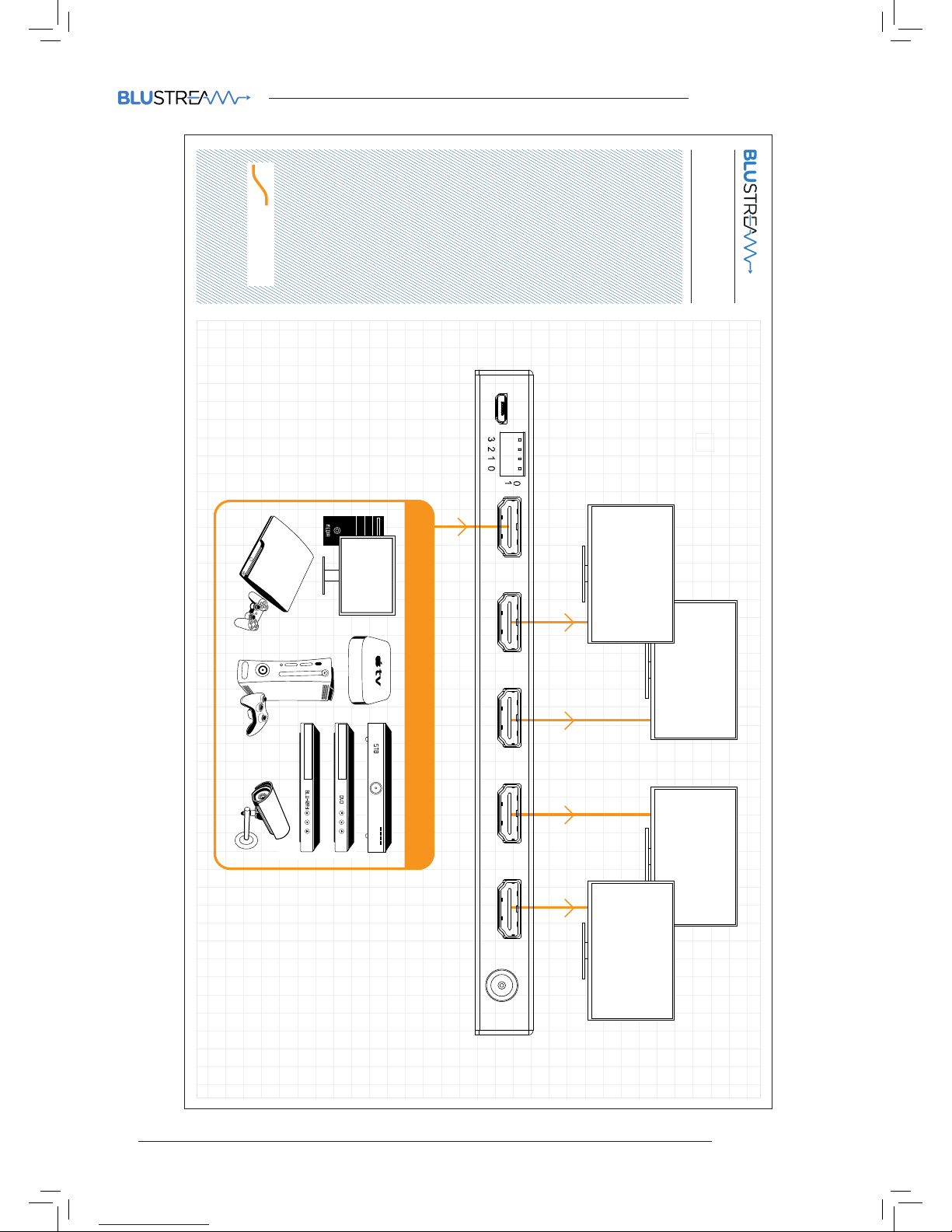
Example Schematic
SP14-V2
HDMI
DISPLAY 2
DISPLAY 1
DISPLAY 3
DISPLAY 4
1 SOURCE
Update
DC
5V
Input Output 2Output 1 Output 4Output 3
SP14 -V2
Page 7

SP14-V2 USER MANUAL
07
contact [email protected] / [email protected]
Specifications
Package Contents:
• Video Input Connectors: 1x HDMI Type A
• Video Output Connectors: 4x HDMI Type A
• EDID: 4-pin DIP Switch
• Dimensions (W x D x H): 175mm x 84mm x 15mm, without feet
• Shipping Weight: 0.5kg
• Operating Temperature: 32°F to 104°F (0°C to 40°C)
• Storage Temperature: -4°F to 140°F (-20°C to 60°C)
• Power Supply: 1x 5V 2A DC
• 1 x SP14-V2
• 1 x 5V/2A power supply
• 1 x User manual
Maintenance
Clean this unit with a so, dry cloth. Never use alcohol, paint thinner or benzene to clean this unit.
Page 8

www.blustream.co.uk
www.blustream.com.au
 Loading...