

Page 1
Blustream Multicast
ACM200 - Advanced Control Module
User Manual
Vid eo LAN(P oE)
Contr ol LAN
IR Ctr l
IR
5V
12V
DC 12V
Power
Link Link
PoE
IO Lev el
Reset
VOut
IO4
IO3
IO2
IO1
5V Norma l
RS-23 2
MCU
12V
ACM200
Yellow Green Yellow Green
MULTICAST
Revision 1.0 - January 2019
Page 2

ACM200 USER MANUAL
02
www.blustream.co.uk / www.blustream.com.au
Surge protection device
recommended
This product contains sensitive electrical
components that may be damaged
by electrical spikes, surges, electric
shock, lightning strikes, etc. Use of
surge protection systems are highly
recommended in order to protect and
extend the life of your equipment.
Safety and performance notice
Do not substitute or use any other power
supply other than approved PoE network
products or approved Blustream power
supplies.
Do not disassemble the ACM200 unit
for any reason. Doing so will void the
manufacturer’s warranty.
Contents
Thank you for purchasing
this Blustream product
For optimum performance and safety,
please read these instructions carefully
before connecting, operating or adjusting
this product. Please keep this manual for
future reference.
Introduction 03
Features 03
Panel Descriptions - ACM200 04
ACM200 Control Ports 05
ACM200 Control Ports - IR Control 06
ACM200 Network Connection - Schematic Diagram 07
Web-GUI Guide Overview 08
Web-GUI - Log In 08
Web-GUI - New Project Set-up Wizard 09 - 13
Web-GUI - Menu Overview 14
Web-GUI - Drag & Drop Control 15
Web-GUI - Video Wall Control 16
Web-GUI - Preview 17
Web-GUI - Project Summary 18
Web-GUI - Transmitters 19 - 20
Web-GUI - Transmitters - EDID Help & EDID Copy 21
Web-GUI - Receivers 22 - 23
Web-GUI - Receivers - Scaling Help & OSD Help 24
Web-GUI - Fixed Signal Routing 25
Web-GUI - Fixed Routed Audio & IR 26
Web-GUI - Fixed Routed USB / KVM & CEC 27
Web-GUI - New Video Wall Configuration 28 - 32
Web-GUI - Existing Video Wall Configuration 33
Web-GUI - Users 34 - 35
Web-GUI - Settings 36 - 37
Web-GUI - Update Firmware 38 - 40
Web-GUI - Update Admin Password 40
RS-232 (Serial) Routing 41
Specifications, Package Contents & Maintenance 42
Blustream IR, RS-232 & Telnet Commands 43 - 52
Troubleshooting 53
Computer Settings - enabling TFTP & Telnet 54 - 57
Notes 58
Page 3

ACM200 USER MANUAL
03
contact [email protected] / [email protected]
Introduction
Impotant Note:
The Blustream Multicast system distributes HDMI video over Layer 3 Managed network hardware. It is advised that
Blustream Multicast devices are connected on an independent network switch to prevent unnecessary interference,
or reduction in signal performance due to other network devices bandwidth requirements.
Please read and understand the instructions in this manual and ensure that the network switch is configured
correctly prior to connecting any Blustream Multicast devices. Failure to do so could result in problems with
configuration of the system and video performance.
• Web interface module for configuration and control of the Blustream Multicast system
• Intuitive 'Drag & Drop' source selection with video preview feature for active monitoring of system status
• Advanced signal management for independent routing of Video, Audio, IR, RS-232, USB/KVM & CEC.
• Auto system configuration
• 2x RJ45 LAN connections to bridge existing network to Multicast video distribution network, resulting in:
- Better system performance as network traic is separated
- No advanced network setup required
- Independent IP address per LAN connection
- Allows simplified TCP / IP control of Multicast system
• RS-232 integration for control of Multicast system
• IR integration for control of Multicast system
• PoE (Power over Ethernet) to power ACM200 from PoE switch
• Local 12V power supply (optional) should switch not support PoE
• Support for iOS and Android App control (not available at initial release)
• 3rd party drivers available for major home control brands
The Blustream UHD Multicast distribution platform allows distribution of HDMI video over a 1Gb Network switch.
The ACM200 Control Module allows advanced third party control of the Multicast system using TCP / IP, RS-232 and
IR.
The ACM200 includes a web interface module for control and configuration of the Multicast system and features
'Drag & Drop' source selection with media preview and independent routing of Video, Audio, IR, RS-232, and USB /
KVM.
Pre-built Blustream device drivers simplify Multicast installation and negate the need for an understanding of
complex network infrastructures.
Features
Page 4
ACM200 USER MANUAL
04
www.blustream.co.uk / www.blustream.com.au
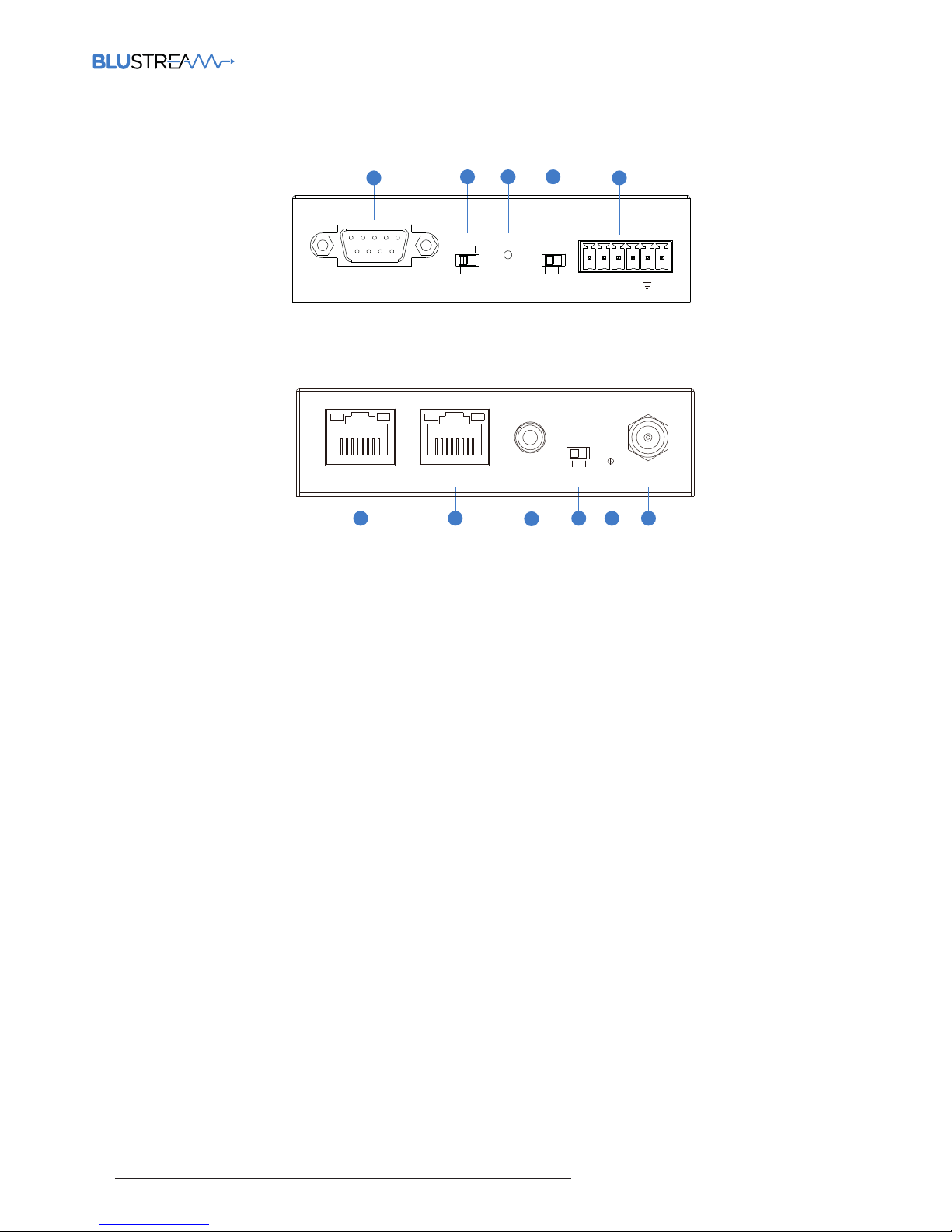
ACM200 - Front Panel
2
1
4
9
8
7
6
1 RS-232 Control Port – connect to a third party
control device for control of the Multicast system
using RS-232.
2 MCU Upgrade Switch - use when upgrading MCU
firmware only. Leave in normal position for
standard operation.
3 Reset Switch - short press resets the ACM200, long
press (10 seconds) factory defaults the ACM200.
4 IO Level Switch - reserved for future use.
5 IO Level Phoenix Connector - reserved for future
use.
6 Video LAN (PoE) Port - connect to the network
switch that the Blustream Multicast components
are connected to.
7 Control LAN Port - connect to existing network
that a third party control system resides on. The
Control LAN port is used for Telnet/IP control of the
Multicast system. Not PoE.
8 IR Ctrl (IR Input) – 3.5mm stereo jack. Connect to
third party control system if using IR as the chosen
method of controlling the Multicast system. When
using the included 3.5mm stereo to mono cable,
ensure the cable direction is correct.
9 IR Switch - adjust IR input voltage level between 5V
or 12V input for IR Ctrl.
q Power LED Indicator - LED is on when the device is
powered on.
w Power Port – use 12V 1A DC adaptor (sold
separately) if not using a PoE network switch.
ACM200 - Rear Panel
Panel Descriptions - ACM200
IO Lev el
Reset
VOut
IO4
IO3
IO2
IO1
5V Norma l
RS-23 2
MCU
12V
ACM200
5
Vid eo LAN(P oE)
Contr ol LAN
IR Ctr l
IR
5V
12V
DC 12V
Power
Link Link
PoE
IO Lev el
Reset
VOut
IO4
IO3
IO2
IO1
5V Norma l
RS-23 2
MCU
12V
ACM200
Yellow Green Yellow Green
11
3
10
Page 5
ACM200 USER MANUAL
05
contact [email protected] / [email protected]
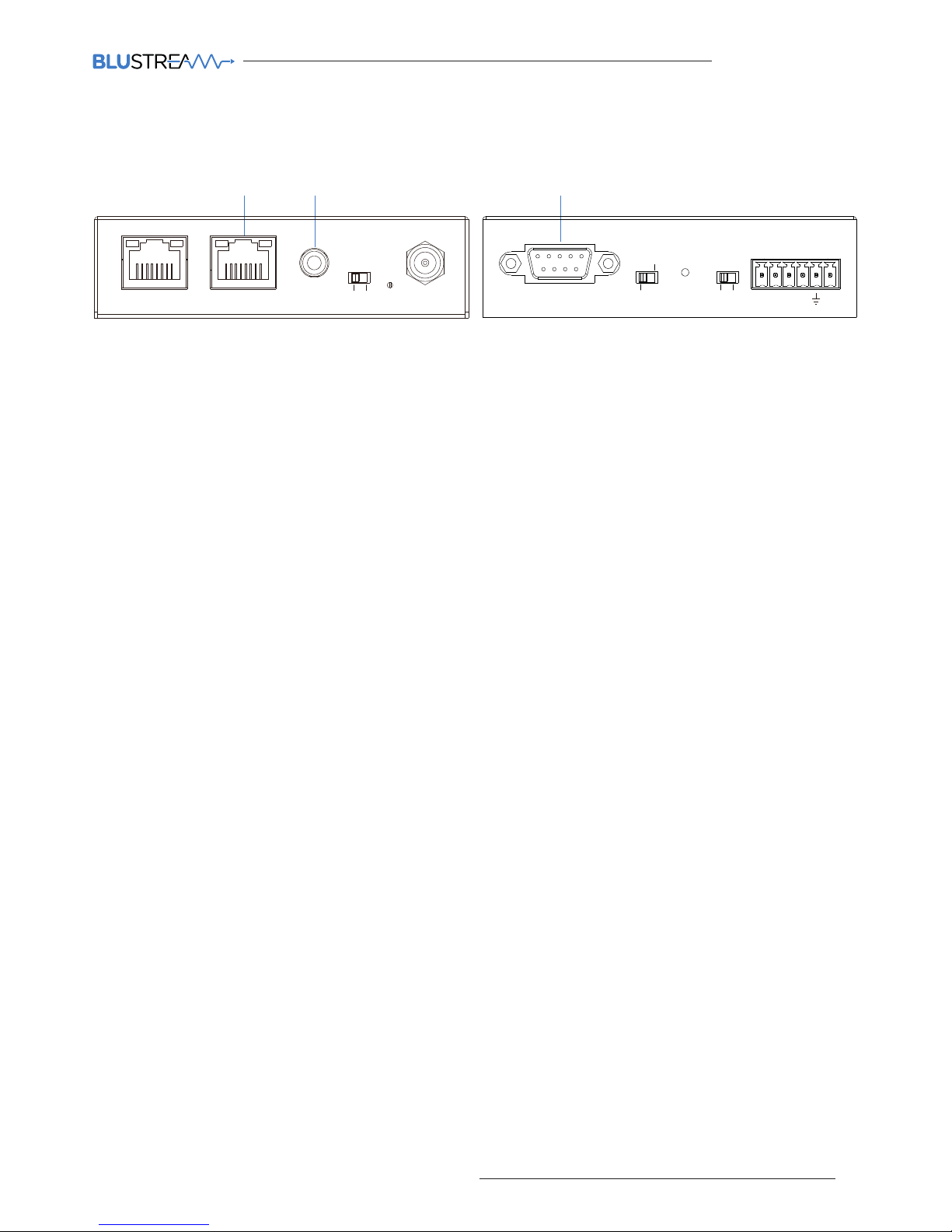
The ACM200 communication ports are located on both end panels and include the following connections:
Connections:
A. TCP/IP – for full Multicast system control (RJ45 Connector)
B. Infrared (IR) Input* - for Multicast switching control only (3.5mm stereo jack)
C. RS-232 – for full Multicast system control / RS-232 guest mode (DB9)
* Please note: the ACM200 can be used with both 5V and 12V IR systems. Please ensure that the IR switch (adjacent
to the IR port) is correctly selected to the specification of the IR input voltage required.
TCP/IP:
The Blustream ACM200 can be controlled via TCP/IP.
For the full list of protocols please see ‘RS-232 & Telnet Commands’ located at the rear of this manual.
A ‘straight-through’ RJ45 patch lead should be used when connected to a network switch.
Control Port: 23
Default IP: 192.168.0.225
Default Username: admin
Default Password: 1 2 3 4
RS-232:
The Blustream ACM200 can be controlled via serial using the serial DB9 connector. Default settings below:
For the full list of command protocols please see ‘RS-232 & Telnet Commands’ located at towards rear of this
manual.
Baud Rate: 57600
Data Bit: 8-bit
Parity: None
Stop Bit: 1-bit
Flow Control: None
The Baudrate for the ACM200 can be adjusted using the ACM200 built-in web-GUI, or by issuing the following
command via RS-232 or Telnet:
RSB x : Set RS-232 Baud Rate to X bps
Where X = 0 : 115200
1 : 57600
2 : 38400
3 : 19200
4 : 9600
ACM200 Control Ports
A
C
B
IO Lev el
Reset
VOut
IO4
IO3
IO2
IO1
5V Norma l
RS-23 2
MCU
12V
ACM200
Vid eo LAN (Po E)
Contr ol LAN
IR Ctr l
IR
5V
12V
DC 12V
Power
Link Lin k
PoE
IO Lev el
Reset
VOut
IO4
IO3
IO2
IO1
5V Norma l
RS-23 2
MCU
12V
ACM200
Yellow Green Yellow Green
Page 6
ACM200 USER MANUAL
06
www.blustream.co.uk / www.blustream.com.au
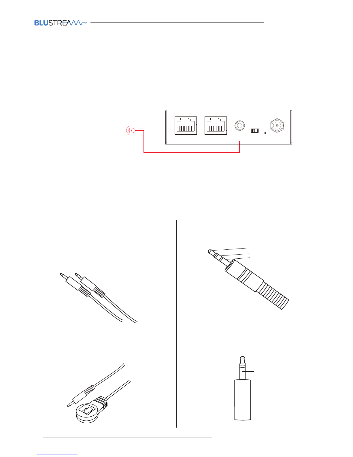
The Multicast system can be controlled using local IR control from a third party control system. Source selection is
the only feature available when using local IR control - advanced features of the ACM200 such as video wall mode,
audio embedding etc. can only be achieved using RS-232 or TCP/IP control.
Blustream have created 16x input & 16x output IR commands allowing source selection of up to 16x IPxxxUHD-TX
Transmitters on up to 16x IPxxxUHD-RX Receivers. For systems larger than 16x source devices (IPxxxUHD-TX) RS-232
or TCP/IP control will be required.
ACM200 Control Ports - IR Control
Link
RXTX
CH Select
IR IR
Rx
Tx
Gnd
RS-232
CH
IP100UHD-RXMULTICAST UHD
IR Receiver - IRR - stereo 3.5mm jack (optional)
Blustream 5V IR receiver to receive an IR signal and
distribute through Blustream products
Wiring pin - IR-CAB - stereo 3.5mm jack:
Signal
5V
Ground
The ACM200 is compatible with both 5V and 12V IR equipment. When the ACM200 is being used to receive an IR
input into the IR Ctrl port, the adjacent switch must be toggled correctly to suit the IR voltage line of the chosen
control system before connection.
Please note: Blustream IR accessories are all 5V
Third Party Control System
(source selection only)
Vid eo L AN( PoE )
Con trol LAN
IR Ctr l
IR
5V
12V
DC 12V
Pow er
Lin k Lin k
PoE
IO Lev el
Res et
VOu t
IO4
IO3
IO2
IO1
5V Nor mal
RS- 232
MCU
12V
ACM200
Yellow Green Yellow Green
3.5mm Stereo to Mono Cable - IR-CAB (included)
Blustream IR Control cable 3.5mm Mono to 3.5mm
Stereo for linking third party control solutions to
Blustream products.
Compatible with 12V IR third party products.
Please note: Cable is directional as indicated
Wiring pin - IR-CAB - mono 3.5mm jack:
Signal
Ground
Page 7
ACM200 USER MANUAL
07
contact [email protected] / [email protected]
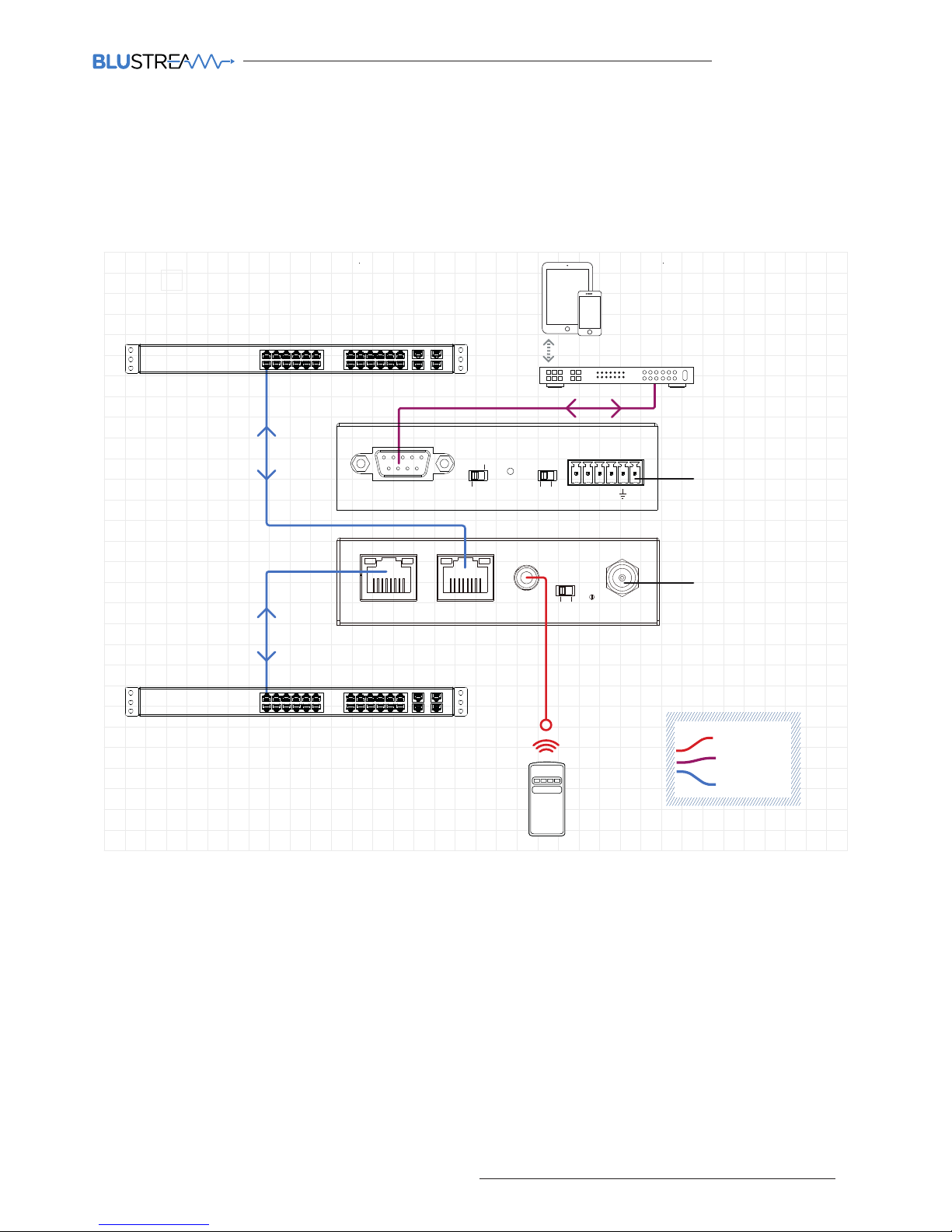
ACM200 Network Connection
The ACM200 acts as a bridge between the control network and video network to ensure that the data travelling
between the two networks are not mixed. The ACM200 must be connected via CAT cable up to 100m in length in
accordance with typical networking requirements.
IO Lev el
Res et
VOu t
IO4
IO3
IO2
IO1
5V Nor mal
RS- 232
MCU
12V
ACM200
Vid eo L AN( PoE)
Con trol LAN
IR Ctr l
IR
5V
12V
DC 12V
Pow er
Lin k Lin k
PoE
Yellow Green Yellow Green
Reserved for future update
Control Processor
Optional 12V PSU
where no PoE is available
Multicast UHD
Network Switch
Customer Home / Business
Network Switch
1G Managed Network Switch
1G Managed Network Switch
RS-232
LAN Cable
IR Cable
IO Leve l
Res et
VOu t
IO4
IO3
IO2
IO1
5V Nor mal
RS- 232
MCU
12V
ACM200
Vide o LAN (PoE)
Con trol LAN
IR Ctrl
IR
5V
12V
DC 12V
Pow er
Lin k Lin k
PoE
Yellow Green Yellow Green
Reserved for future update
Control Processor
Optional 12V PSU
where no PoE is available
Multicast UHD
Network Switch
Customer Home / Business
Network Switch
1G Managed Network Switch
1G Managed Network Switch
Page 8
ACM200 USER MANUAL
08
www.blustream.co.uk / www.blustream.com.au
Web-GUI Guide Overview
The web-GUI of the ACM200 allows for full configuration of a new system, as well as on-going maintenance and
control of an existing system through a web portal. The ACM200 can be accessed on any internet connected device
including: tablets, smart phones and laptops that are on the same network.
Web GUI - Log In
Before logging in to the ACM200, ensure that the control device (i.e. laptop / tablet) is connected to the same
network as the ACM200's Control Port. There are instructions of how to amend the static IP address of a PC at the
rear of this manual.
To log in, open a web browser (i.e. Firefox, Internet Explorer etc.) and navigate to the default static IP address of the
ACM200 which is:
192.168.0.225
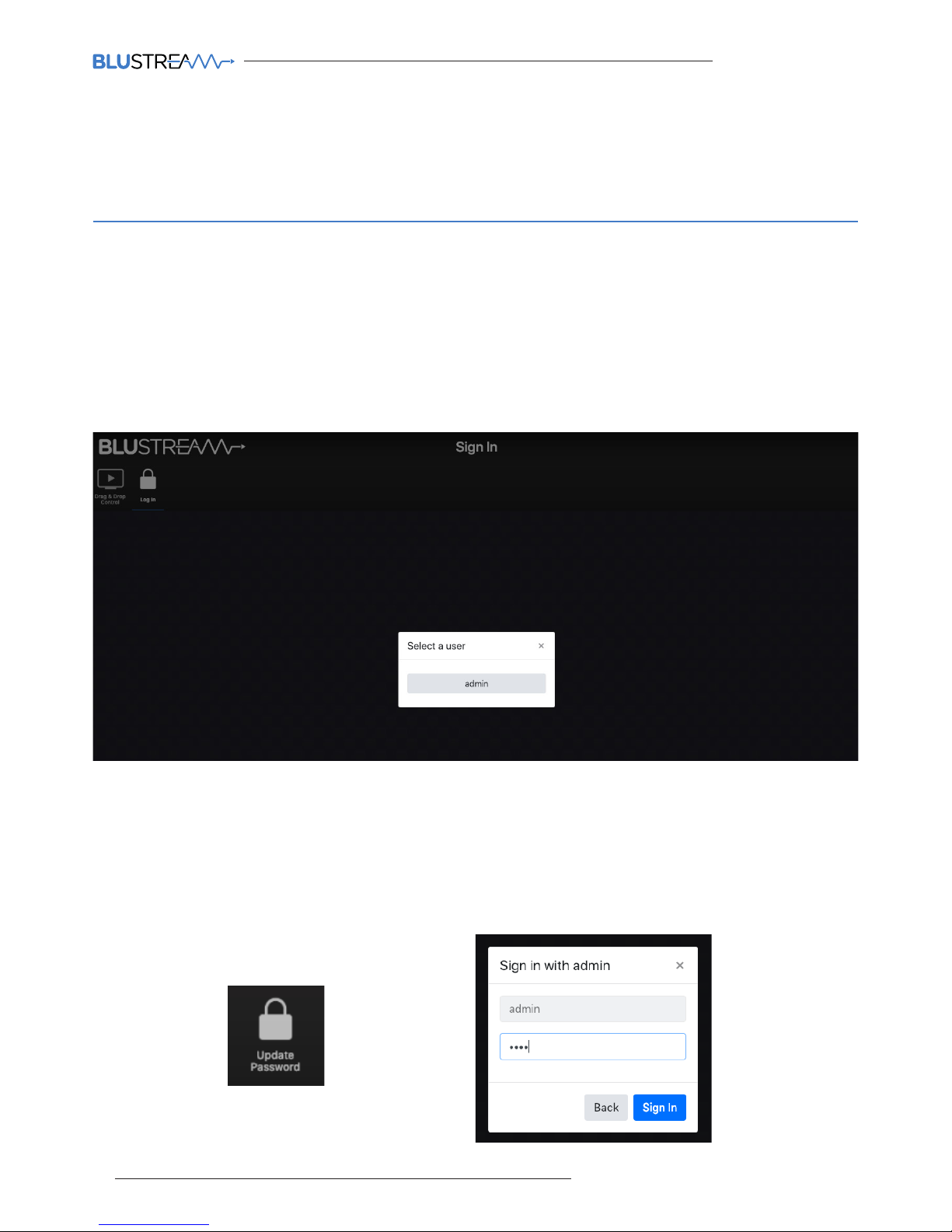
The sign in page is presented on connection to the ACM200. Once Users have been created within the system, this
screen will be populated with the Users previously configured for future log ins. The default Admin password is:
1 2 3 4
Please note: the Admin password can be changed once logged in using the 'Update Password' option located in
the main menu options.
Page 9
ACM200 USER MANUAL
09
contact [email protected] / [email protected]
On first log in of the ACM200, a Set-up Wizard for configuring all components of the Multicast system will be
presented. This has been designed to speed up new system configuration as all default / new Multicast Transmitters
& Receivers can be connected to the network switch at the same time, whilst not resulting in an IP conflict during
the system configuration. This results in a system in which all components are automatically and sequentially
assigned a name and IP address ready for basic system use.
Web-GUI - New Project Set-up Wizard
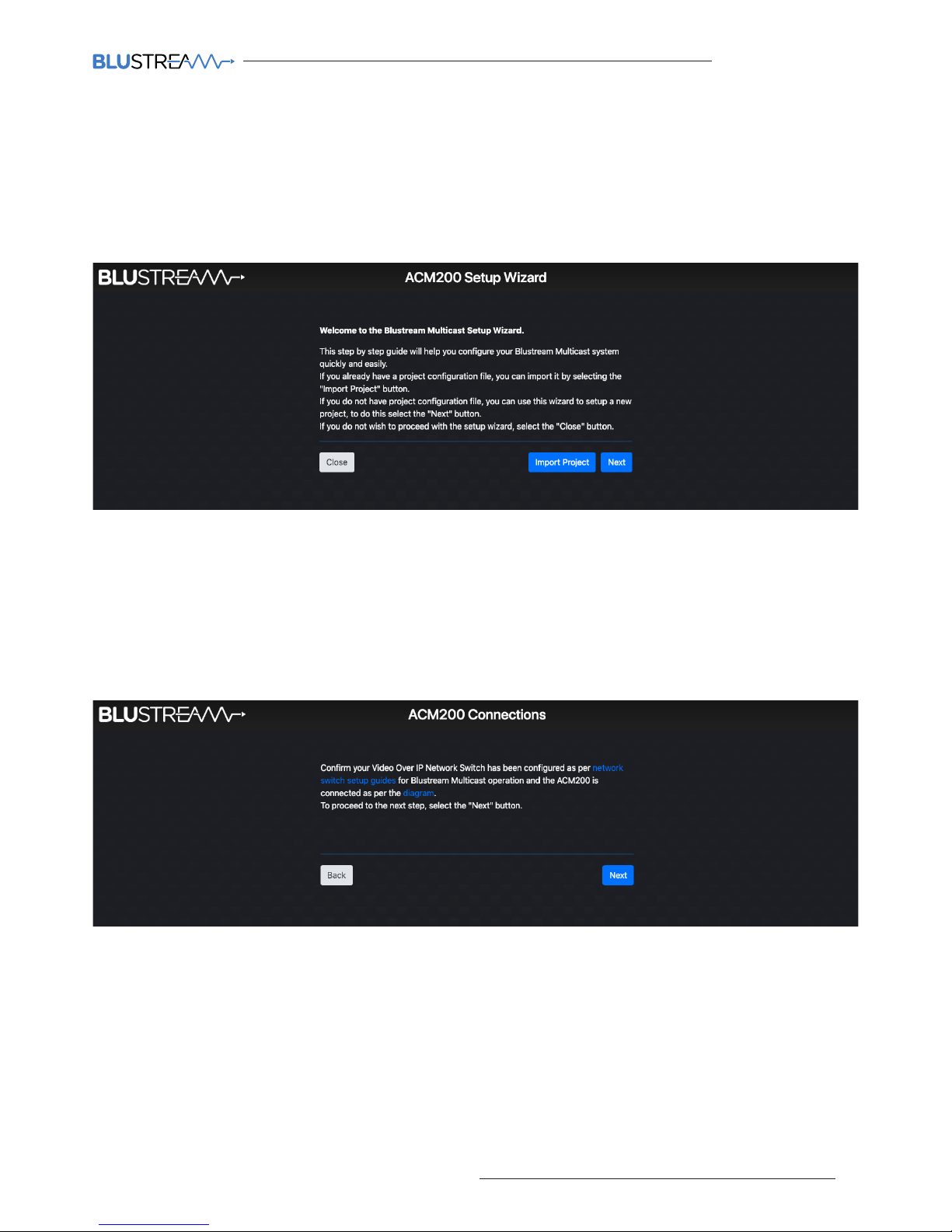
The ACM200 Set-up Wizard can be cancelled by clicking 'Close'. Please be aware that the system will not be
configured at this point, but can be continued by visiting the 'Project' menu (see page 18). If a project file is already
available (i.e. replacing an ACM200 on an existing site), this can be imported by using the .json file by clicking
'Import Project'.
Click 'Next' to continue set-up:
If at this point the Network Switch is not configured for use with the Blustream Multicast system, click on the
hyperlink 'network switch setup guides' to navigate to a centralised webpage containing common Network Switch
Guides.
An example schematic diagram for the connections of the ACM200 can be accessed by clicking the hyperlink
marked 'diagram'. This will ensure the ACM200 is connected correctly to the wider Multicast system before the
Set-up Wizard begins. Once the connections of the ACM200 are confirmed click 'Next'. The connections diagram is
included on page 07 of this guide.
Page 10
ACM200 USER MANUAL
10
www.blustream.co.uk / www.blustream.com.au
Web-GUI - New Project Set-up Wizard - continued...
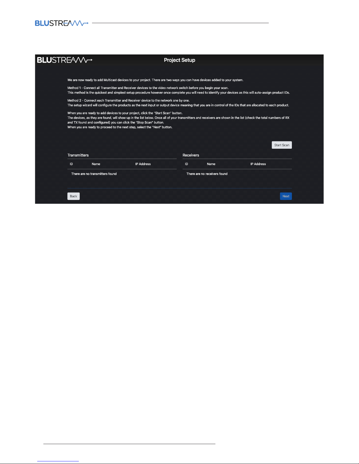
There are two methods for adding new Multicast Transmitter and Receiver devices to a system, please choose one
before clicking 'Start Scan':
Method 1: connect ALL Blustream Multicast Transmitter's and Receiver's to the network switch with their factory
default IP addresses (169.254.100.254). This method will quickly configure all devices with their own individual IP
addresses based on the following:
Transmitters:
The first Transmitter will be given the IP address of 169.254.3.1.
The next Transmitter will be assigned an IP address of 169.254.3.2 and so on....
Once the IP range of 169.254.3.x is filled (254 units), the ACM200 will auto assign an IP address of
169.254.4.1 and so on...
Once the IP range of 169.254.4.x is filled the ACM200 will auto assign an IP address of 169.254.5.1 and so on until
169.254.4.254
Receivers:
The first Receiver will be given the IP address of 169.254.6.1. The next Receiver will be assigned an IP address of
169.254.6.2 and so on....
Once the IP range of 169.254.6.x is filled (254 units) the ACM200 will auto assign an IP address of
169.254.7.1 and so on...
Once the IP range of 169.254.7.x is filled the ACM200 will auto assign an IP address of 169.254.8.1 and so on until
169.254.8.254
Once complete, devices will need to be identified manually - this method will auto-assign IP addresses and ID's to
each device connected to the network switch randomly (not by switch port).
Method 2: connect each Blustream Multicast Transmitter and Receiver to the network one-by-one. The Set-up
Wizard will configure the units sequentially as they are connected / found. This method allows for the control of
the sequential assigning of IP addresses and ID's of each device - the Transmitter / Receiver units can therefore be
labelled accordingly.
Page 11
ACM200 USER MANUAL
11
contact [email protected] / [email protected]
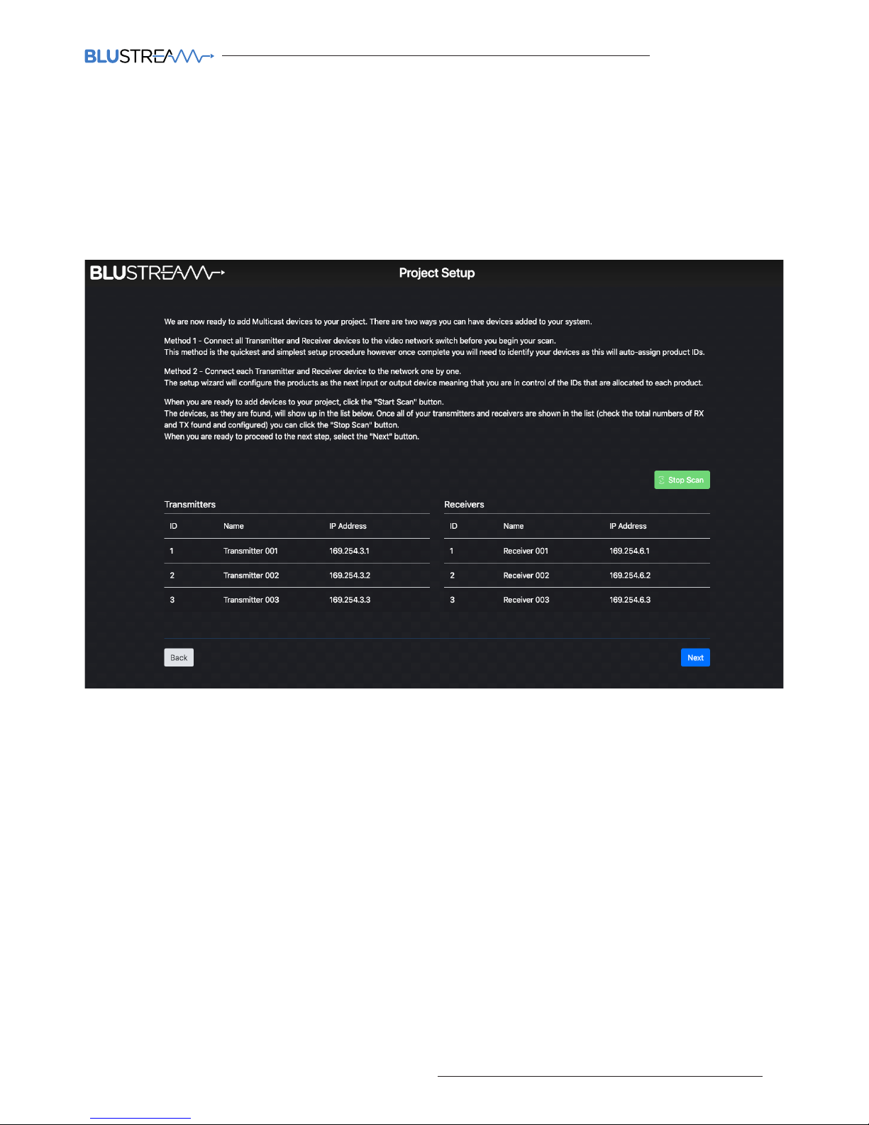
Once the set-up method to configure the system has been chosen, hit the 'Start Scan' button.
The ACM200 will search for new Blustream Multicast devices on the network and will continue to search for new
devices until such time as:
- The 'Stop Scan' button is pressed
- The 'Next' button is clicked to progress the Set-up Wizard aer all units have been found
Web-GUI - New Project Set-up Wizard - continued...
As new devices are found by the ACM200, the units will populate to the relevant columns marked Receivers or
Transmitters. It is recommended to label the individual units at this point.
Once all units have been found and configured, click 'Stop Scan', then 'Next'.
Page 12
ACM200 USER MANUAL
12
www.blustream.co.uk / www.blustream.com.au
Web-GUI - New Project Set-up Wizard - continued...
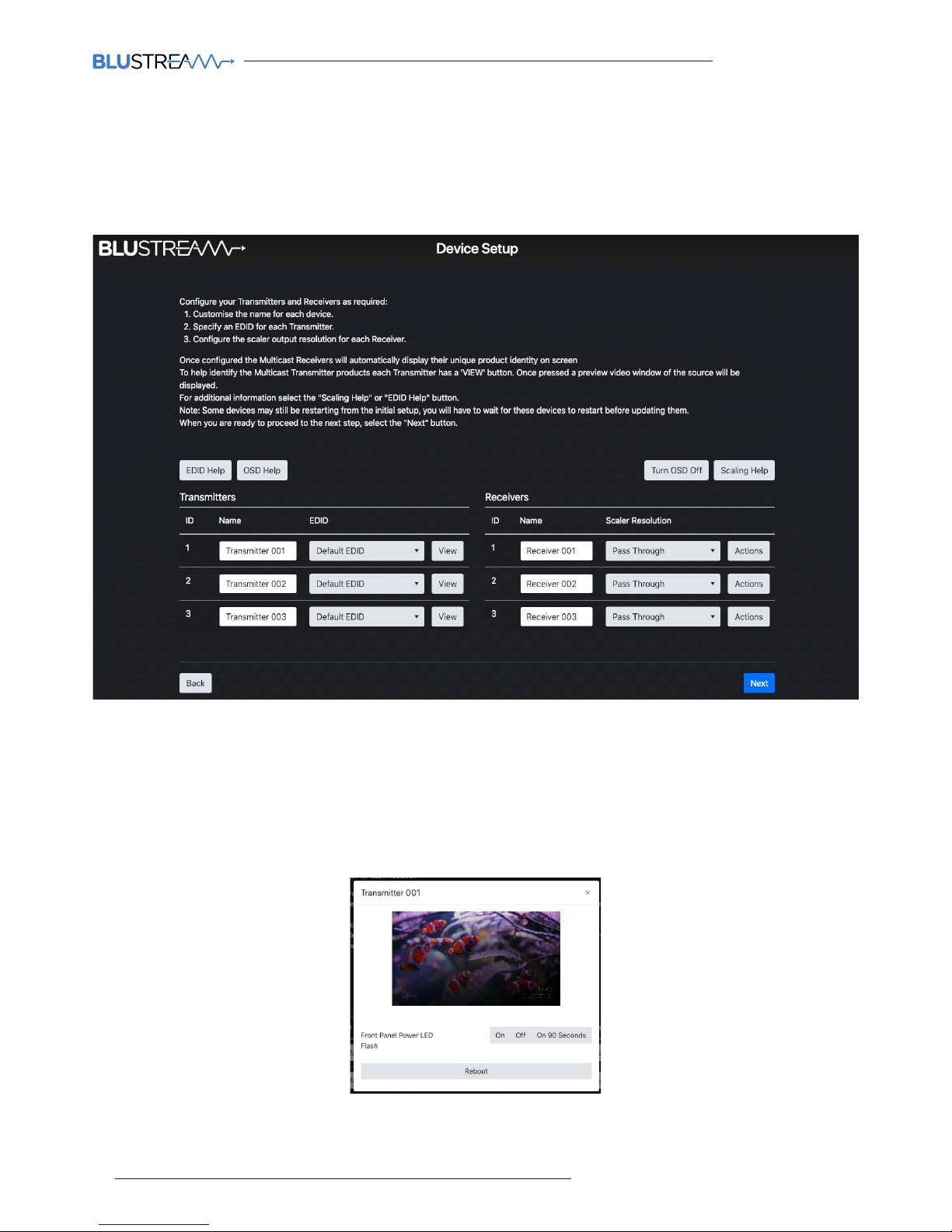
The device setup page allows for naming of Transmitter and Receiver products and for EDID and Scaler settings to
be adjusted. EDID and Scaler settings for the individual Transmitters or Receivers can be set as required. For help
with EDID and Scaler settings, click the relevant buttons marked 'EDID Help' (for help wth EDID settings, see page
21), or 'Scaling Help', refer to page 24.
Features of the Device Set-up page include:
1. Name of Devices - during configuration the Transmitters / Receivers are automatically assigned default names
i.e. Transmitter 001 etc. Transmitter / Receiver names can be amended by typing in the corresponding box.
2. EDID - fix the EDID value for each Transmitter (source). This is used to request specific video and audio
resolutions for the source device to output. Basic help with EDID selection can be obtained by clicking the
button marked 'EDID Help'. See page 19 for a full list of EDID settings that can be applied.
3. View - opens the following pop-up:
This pop-up shows an image preview of the media currently being streamed by the Transmitter unit. The ability to
identify the unit by flashing the front panel LED's on the unit, and the ability to Reboot the unit.
Page 13
ACM200 USER MANUAL
13
contact [email protected] / [email protected]
Web-GUI - New Project Set-up Wizard - continued...
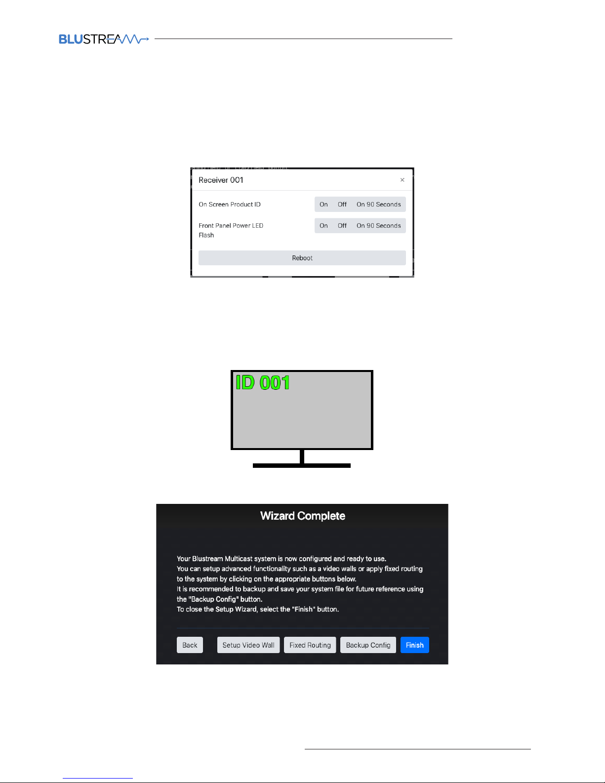
This pop-up gives you the ability to display the product ID on the connected screen / display by way of an OSD
(On Screen Display) as an overlay to the media being accepted the by Receiver. The ability to identify the unit by
flashing the front panel LED's, and the ability to Reboot the unit is contained here.
7. Turn OSD On / O - toggles the product ID onto the connected screen / display by way of an OSD.
8. Next - continues to the Set-up Wizard Completion page
The Wizard Completion page finalises the basic configuration process and provides links for advanced set-up
options for Video Walls, Fixed Signal Routing (IR, RS-232, Audio etc), and the ability to back-up to a configuration file
(recommended).
Click 'Finish' once done to continue to the 'Drag & Drop Control' page, logged in as Administrator (see page 15).
4. Scaler - adjust the output resolution using the built-in video scaler of the Multicast Receiver. The scaler is
capable of both upscaling and downscaling the incoming video signal. See page 22 for a full list of Scaler output
settings that can be applied.
5. Refresh - click here to refresh all current information on the products within the system.
6. Actions - opens the following pop-up:
Page 14

ACM200 USER MANUAL
14
www.blustream.co.uk / www.blustream.com.au
Web-GUI - Menu Overview
The 'User Interface' menu gives an end user the ability to switch and preview the Multicast system without
allowing access to any settings that can change the overall infrastructure of the system.
1. Drag & Drop Control - used for ‘Drag & Drop’ control of source selection for each Multicast Receiver including
image preview of source devices.
2. Video Wall Control - used for ‘Drag & Drop’ control of source selection for each video wall array within the
system, including image preview of source devices.
3. Preview - used to show the active video stream from any connected Multicast Transmitter or Receiver
4. Project - used to configure a new or existing Blustream Multicast system.
5. Transmitters - shows a summary of all Multicast Transmitters installed, with options for EDID management,
checking FW version, updating settings, adding new TX’s, replacing or rebooting devices.
6. Receivers - shows a summary of all Multicast Receivers installed, with options for resolution output (HDR
/ scaling), function (video wall mode / matrix), updating settings, adding new RX’s, replacing or rebooting
devices.
7. Fixed Signal Routing - used for signal routing allowing independent routing of IR, RS-232, USB / KVM, CEC,
Audio and Video signals.
8. Video Wall Configuration - used for the set-up and configuration of Multicast receivers to create a video wall
array of up to a size of 9x9, including: bezel / gap compensation, stretch / fit, and rotation.
9. Users - used to set-up or manage users of the system.
10. Settings - access to various system settings including: network and resetting devices.
11. Update Devices - used for applying the latest firmware updates to the ACM200 and connected Blustream
Multicast Transmiters and Receivers.
12. Update Password - used to update the Administrator password for access to the ACM200 web-GUI.
13. Log Out - log out the current User / Administrator.
1. Drag & Drop Control - used for ‘Drag & Drop’ control of source selection for each Multicast Receiver including
image preview of source devices throughout.
2. Video Wall Control - used for ‘Drag & Drop’ control of source selection for each video wall array within the
system, including image preview of source devices throughout. This icon will only display if there are video
walls configured in the project.
3. Log In - used to log into the system as a User or Administrator
The Administrator menu is accessed from a single password (see page 08 to log in). This menu allows to the
Multicast system to be completely configured with access to all settings and features of the system.
Please note: it is not recommended to leave Administrator access or the Administrator password with an end user.
Page 15
ACM200 USER MANUAL
15
contact [email protected] / [email protected]
Web-GUI - Drag & Drop Control
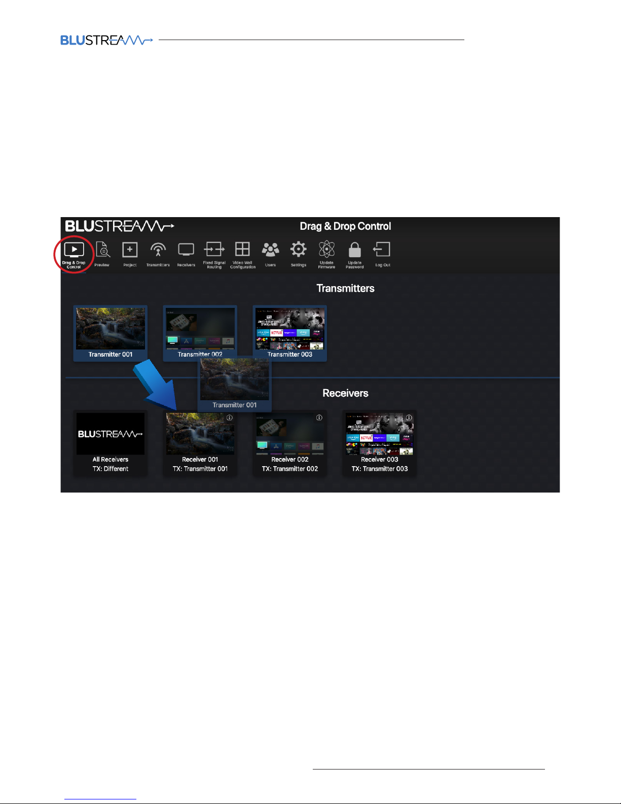
The ACM200 Drag & Drop Control page is used to quickly and intuitively change a source input (Transmitter) for
each display (Receiver). This page has been designed to allow the User to quickly switch the I/O configuration of the
system.
Once the system has been fully configured the Drag & Drop Control page will show all online Multicast Transmitters
and Receivers. All Multicast devices will display the active stream which refreshes every few seconds.
Due to the size of the display window on certain phones, tablets or laptops, should the number of Transmitters and
Receivers be larger than the size available on screen, the User is given the ability to scroll or swipe through available
devices (le to right).
To switch sources, click on the required source and ‘Drag & Drop’ the Transmitter preview onto the required
Receiver product. The Receiver preview window will update with the new live stream of the source selected.
The Drag & Drop switch will amend the Video/Audio stream from Transmitter to Receiver, but not alter any fixed
routing of control signals that have been configured in the ACM200 (see page 25).
Should ‘No Signal’ be displayed in the Transmitter preview window, please check the HDMI source device is
powered on, outputting a signal and is connected via HDMI cable to the Multicast Transmitter unit. Check also
the EDID settings of the Transmitter device (Multicast will not accept 4K60 4:4:4 signals). Should ‘No Signal’ be
displayed inside the Receiver preview window, check the unit is connected and powered from the network (switch)
and has a valid connection to a working Transmitter unit.
There is an 'All Receivers' window located on the le of the Receivers window. Dragging and dropping a Transmitter
onto this window will change the routing for ALL Receivers within the system to watch the source selected. Should
the preview of this window show the Blustream logo, this signifies that there is a mixture of sources being watched
across the range of Receivers within the system. The note underneath 'All Receivers' will display: 'TX: Dierent'.
Please note: the Drag & Drop Control page is also the home page for Guest Users of the Multicast system - only
sources that the Guest or User have permission to view will be visible. For User set-up and permissions, see page 34.
Receivers in Video Wall Mode are not displayed on the Drag & Drop page.
Page 16
ACM200 USER MANUAL
16
www.blustream.co.uk / www.blustream.com.au
Web-GUI - Video Wall Control
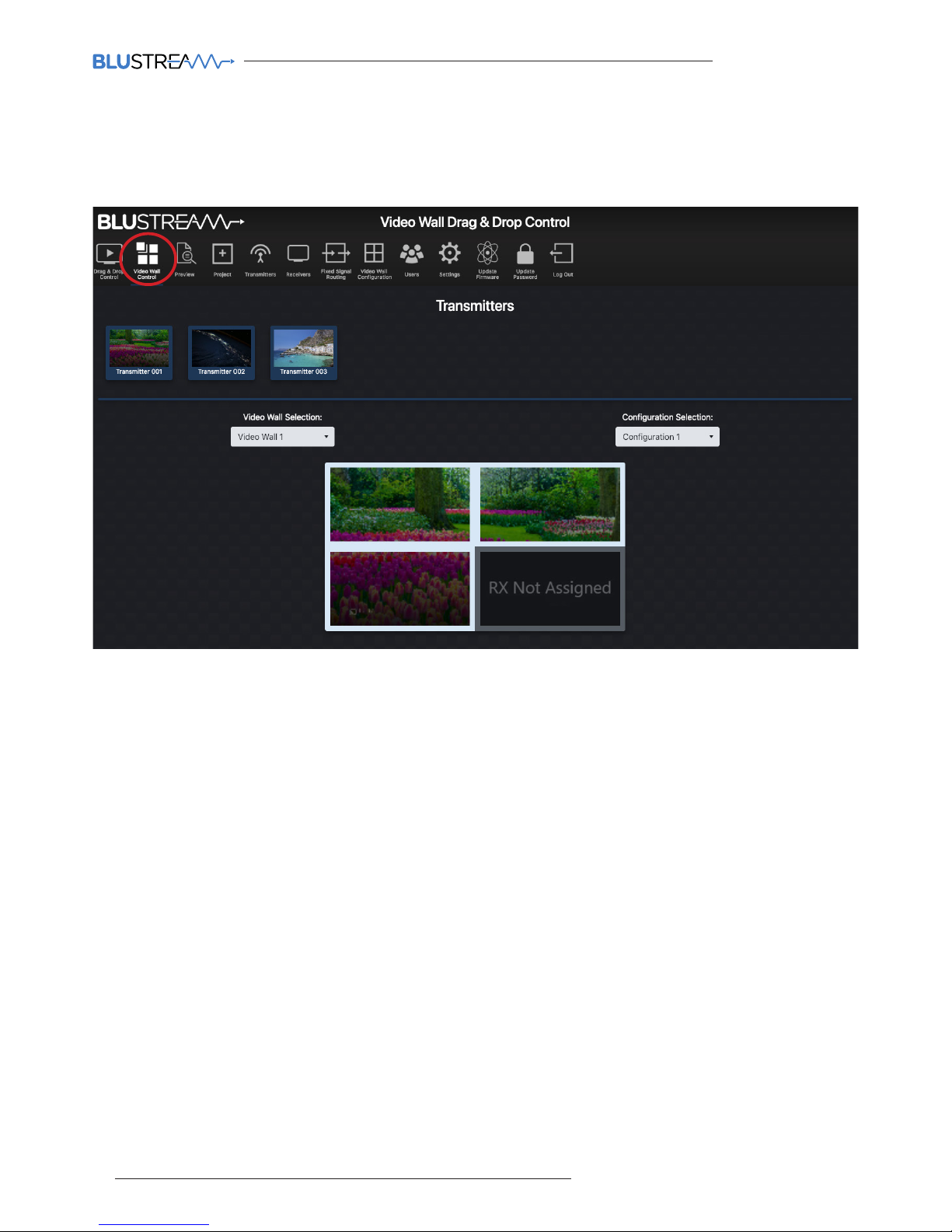
To assist wth simplified Video Wall switching control, there is a separate Video Wall Drag & Drop Control page. This
menu option is only available once a Video Wall has been configured into the ACM200 / Multicast system.
The source (Transmitter) preview windows are shown at the top of the page with the graphical representation of the
Video Wall displayed below.
To switch sources, click on the required source and ‘Drag & Drop’ the Transmitter preview onto the Video Wall array
underneath. The Video Wall will switch all screens within the Video Wall configuration to the selected source. Repeat
this process if dierent groups have been configured within the Video Wall.
Blustream Multicast systems can have multiple Video Walls. Selecting a dierent Video Wall array, or to deploy a
pre-defined Configuration / preset for each Video Wall can be carried out by using the drop down boxes above the
graphical representation of the Video Wall. This graphical representation will automatically update as you select a
dierent Video Wall or Configuration.
Should a screen within a Video Wall display on the GUI show 'RX Not Assigned', this means that the Video Wall does
not have a Blustream Multicast Receiver unit assigned to the array. Please revert back to Video Wall set up to assign
the Receiver accordingly.
For the advanced API commands for control of Video Wall arrays within a Blustream Multicast system, please refer
to the API Commands section at the rear of this manual.
Page 17
ACM200 USER MANUAL
17
contact [email protected] / [email protected]
Web-GUI - Preview
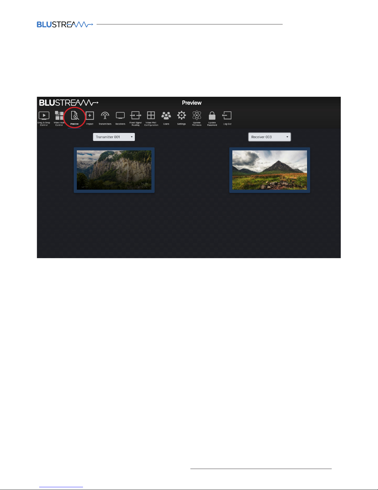
The Preview feature is a quick way to view the media being streamed through the Multicast system once configured.
Used to preview the stream from any HDMI source device into the Multicast Transmitter, or the stream being
received by any Receiver in the system concurrently. This is particularly helpful for debugging and checking source
devices are powered on and outputting a HDMI signal, or to check the I/O status of the system:
The Preview windows show a live grab of the media which automatically updates every few seconds. To select
the Transmitter or Receiver to preview, use the drop down box to select the individual Transmitter or Receiver to
preview.
Page 18
ACM200 USER MANUAL
18
www.blustream.co.uk / www.blustream.com.au
Web-GUI - Project Summary
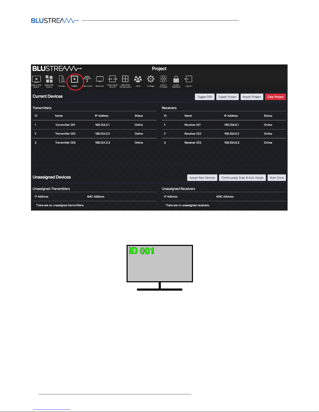
Outlines the units that are currently set-up in the Multicast system as an overview, or for scanning the network for
new devices to assign to the project:
Options on this page:
1. Toggle OSD: turn On / O the OSD (On Screen Display). Toggling the OSD On shows the ID number (i.e. ID
001) of the Multicast Receiver on each display as an overlay to the media being distributed. Toggling OSD O
removes the OSD. See page 24 for more information on the use of OSD.
2. Export Project: create a save file (.json) for the configuration of the system.
3. Import Project: import an already configured project into the current system. This is particularly helpful when
setting up a secondary system or expansion to a current system o-site where the two systems can be merged
into one.
4. Clear Project: resets the ACM200 removing all Transmitters, Receivers and Video Wall Configurations from the
project, reverting the ACM back to the initial wizard configuration. Please note: when 'Clear Project' is applied
only the ACM200 network settings will remain.
5. Continuously Scan & Auto Assign: continuously scan the network and auto assign new Multicast devices to
the next available ID and IP address as connected. If only connecting one new Multicast device, use the 'Scan
Once' option. The ACM200 will continue to scan the network for new Multicast devices until found, or select this
button again to stop the scan.
6. Scan Once: scan the network once for any new Multicast device connected. Once discovered you will be
presented with the option to: 1. manually assign a new device, or: 2. auto assign a new unit to the next available
ID and IP address as connected.
Page 19
ACM200 USER MANUAL
19
contact [email protected] / [email protected]
Web-GUI - Transmitters
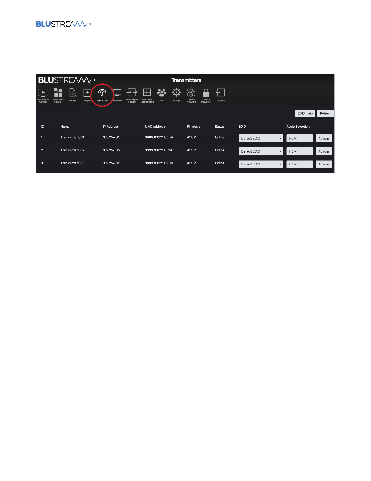
The Transmitter summary page is an overview of all Transmitter devices that have been configured within the
system, with the ability to update the system as required.
Features of the Transmitter summary page include:
1. ID / Input - the ID / Input number is used for control of the Multicast system when using third party drivers.
2. Name - the name of the Transmitter (typically the device attached to the Transmitter).
3. IP Address - the IP address assigned to the Transmitter during configuration.
4. MAC Address - shows the unique MAC address of the Transmitter.
5. Firmware - displays the firmware version currently loaded onto the Transmitter. For more information on
firmware updating, please see 'Update Devices' on page 37.
6. Status - shows the online / oline status of each Transmitter. Should a device show as 'Oline', check the units
connectivity to the network switch.
7. EDID - fix the EDID value for each Transmitter (source). This is used to request specific video and audio
resolutions for the source device to output. Basic help can be obtained on EDID selection by clicking the button
at the top of the page marked 'EDID Help'. For further help on EDID settings, see page 21. EDID selections as
follows:
- Default EDID - the default EDID is for the Transmitter to request a 1080p / 2ch signal from the source device
- 1080i @ 60Hz 2ch - 4K2K 4:2:0 2ch
- 1080i @ 60Hz 5.1ch - 4K2K 4:2:0 5.1ch
- 1080i @ 60Hz 7.1ch - 4K2K 4:2:0 7.1ch
- 1080p @ 60Hz 2ch - 4K2K 4:4:4 2ch
- 1080p @ 60Hz 5.1ch - 4K2K 4:4:4 5.1ch
- 1080p @ 60Hz 7.1ch - 4K2K 4:4:4 7.1ch
- 1080p @ 60Hz / 3D 2ch - DVI 1280 x 1024 @ 60Hz (no audio)
- 1080p @ 60Hz / 3D 5.1ch - DVI 1920 x 1080 @ 60Hz (no audio)
- 1080p @ 60Hz / 3D 7.1ch - DVI 1920 x 1200 @ 60Hz (no audio)
8. Audio Selection - selects either original HDMI audio, or replaces the embedded audio with a local analogue
audio input on the Transmitter. Default setting will be ‘Auto’. Please note: in 'Auto' mode the audio will be
switched to the local analogue audio input of the Transmitter when the 3.5mm audio jack is inserted. This will
only revert back to HDMI audio when the 3.5mm audio jack is removed.
9. Actions - opens a pop-up window with advanced configuration settings. See following page for further
information.
10. Refresh - refresh all current information on the devices within the system.
Page 20
ACM200 USER MANUAL
20
www.blustream.co.uk / www.blustream.com.au
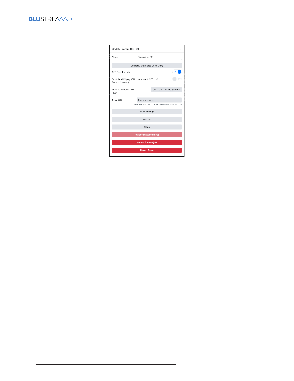
Web-GUI - Transmitters - Actions
The 'Actions' button allows for
advanced features of the units to be
accessed and configured.
Features of the Actions menu include:
1. Name - Transmitter names can be amended by entering a name into the free-form text box. Please note: this is
limited to 16 characters in length, and some special characters may not be supported.
2. Update ID - the ID of a unit is set as default to the same number as the last 3 digits of the units IP address i.e.
Transmitter number 3 is assigned an IP address of 169.254.3.3 and will have an ID of 3. Amending the ID of the
unit is not normally recommended.
3. CEC Pass-through (On / O) - allows for CEC (Consumer Electronic Command) to be sent through the Multicast
system to and from the source device connected to the Transmitter. Please note: CEC must be enabled on the
Receiver unit also for the CEC commands to be sent between. Default setting for this feature is O. If more than
one Blustream Receiver is viewing a Transmitter, the CEC is passed between all devices. Because of this it is
advised to leave CEC disabled on all products unless required.
4. Front Panel Display (On / O) - use this to enable / disable the dual 7-segment LED displays on the front of the
Transmitter. The front panel display of the Multicast unit will automatically time-out aer 90 seconds and turn
o.
5. Front Panel Power LED Flash (On / O / On 90 Seconds) - will flash the power LED on the front panel of
the Transmitter to help identify the device following auto configuration. Options are: flash the power light
continuously, or flash the LED for 90 seconds before the LED goes back to being permanently lit. Please note:
the front panel LED's will automatically time-out aer 90 seconds with the front panel display. Press one of the
CH buttons to wake the unit.
6. Copy EDID - see page 21 for further information on Copy EDID.
7. Serial Settings - turn on serial 'Guest Mode' and set the individual serial port settings for the device (i.e. Baud
Rate, Parity etc).
8. Preview - displays a pop-up window with live a screen grab of the source device connected to the Transmitter.
9. Reboot - reboots the Transmitter.
10. Replace - used to replace an oline Transmitter. Please note: the Transmitter to be replaced must be oline
for this feature to be utilised, and the new Transmitter must be a factory default unit with default IP address:
169.254.100.254.
11. Remove from Project - removes the Transmitter device from the current project.
12. Factory Reset - restores the Transmitter to its original default settings and sets the IP address to:
169.254.100.254.
Page 21
ACM200 USER MANUAL
21
contact [email protected] / [email protected]
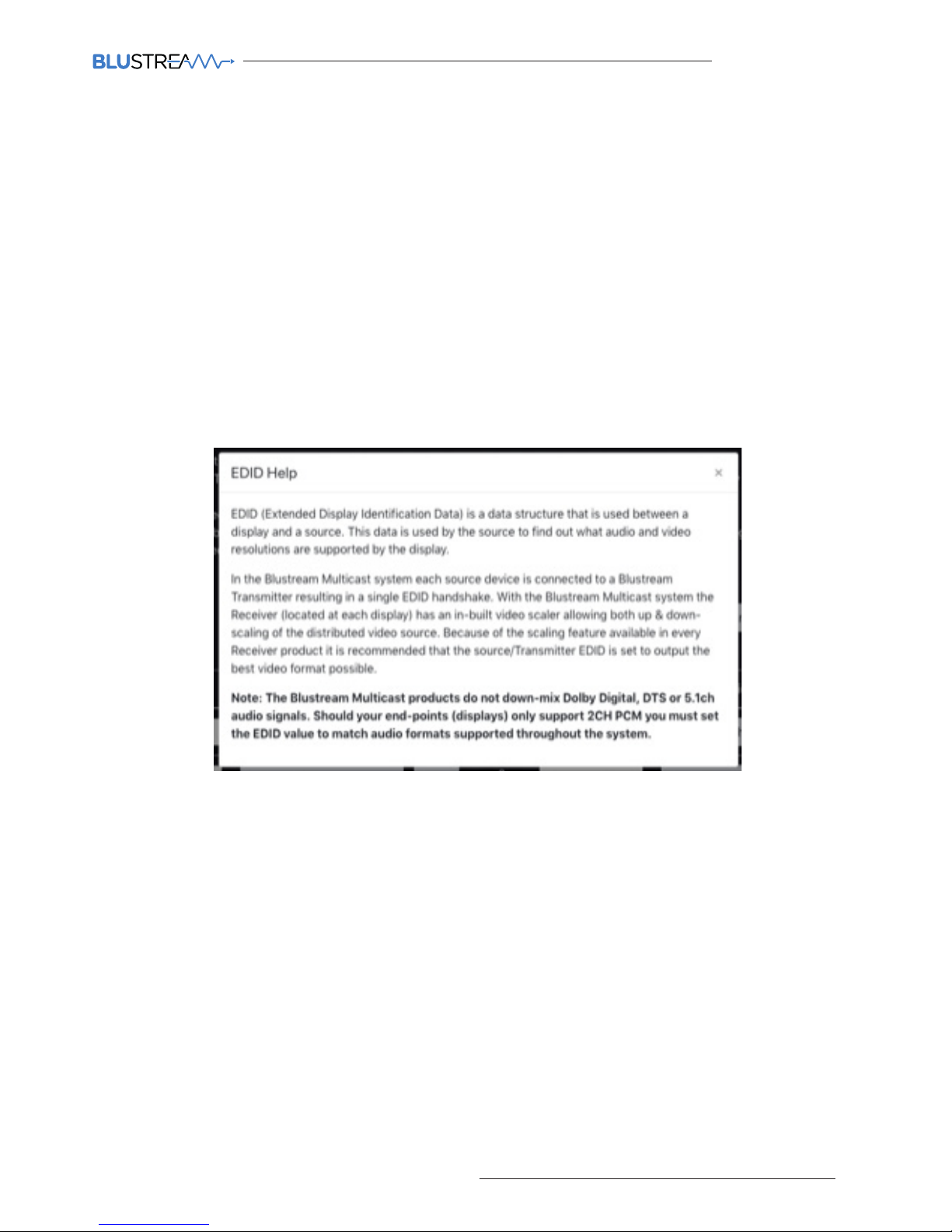
Web-GUI - Transmitters - Actions - EDID Help / Copy EDID
EDID Help:
EDID (Extended Display Identification Data) is a data structure that is used between a display and a source. This
data is used by the source to find out what audio and video resolutions are supported by the display then from this
information the source will discover what the best audio and video resolutions need to be output.
While the objective of EDID is to make connecting a digital display to a source a simple plug-and-play procedure,
issues can arise when multiple displays, or video matrix switching is introduced because of the increased number of
variables.
By pre-determining the video resolution and audio format of the source and display device you can reduce the time
need for EDID hand shaking thus making switching quicker and more reliable.
It is important, where possible, to set the source device to output a video resolution within the limit that the
Multicast IP Transmitter can accept. Where this is not possible, EDID management will request a suitable output
from the source device. Maximum input resolutions as follows: 3840x2160 @ 30Hz 4:4:4 8-bit, 4096x2160 @ 24Hz
4:4:4, 3840x2160 @ 60Hz 4:2:2, 3840x2160 @ 60Hz 4:2:0. Supports 4K with HDR at 30 / 25 / 24Hz.
Copy EDID:
The Copy EDID function allows the EDID of a display to be grabbed and stored within the ACM200. The EDID
configuraiton of the screen can be recalled within the EDID selection of the Transmitter. The displays EDID can then
be applied to any source device not displaying correctly on the screen in question.
It is recommended to ensure that the media from the Transmitter with the custom EDID displays correctly on
other displays within the system.
Please note: it is important that only one screen is viewing the Transmitter at the time the EDID Copy takes place.
Page 22
ACM200 USER MANUAL
22
www.blustream.co.uk / www.blustream.com.au
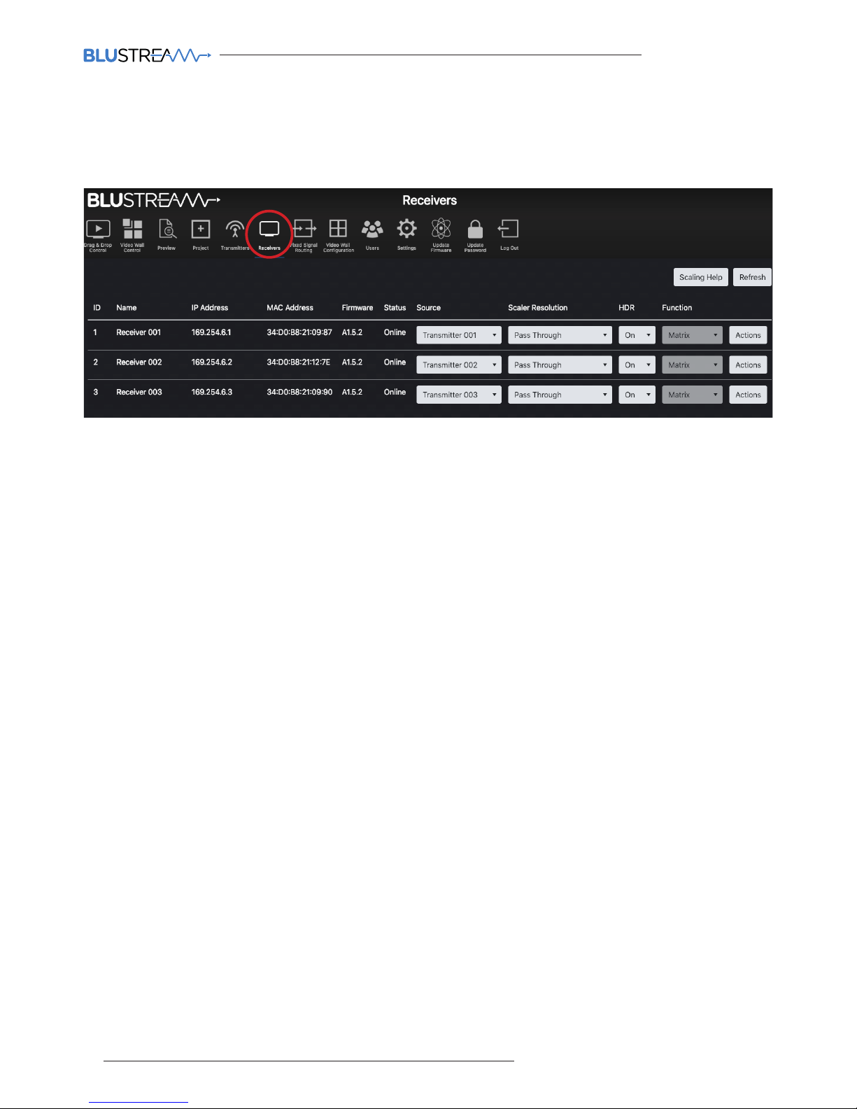
Web-GUI - Receivers
The Receiver summary window gives an overview of all the Receiver devices that have been configured within the
system, with the ability to update the system as required.
Features of the Receiver summary page include:
1. ID / Output - the ID / output number is used for control of the Multicast system when using third party drivers.
2. Name - the name of the Receivers (typically the device attached to the Receiver) are automatically assigned
default names i.e. Receiver 001 etc. Receiver names can be amended within the Device Setup page (within the
Wizard), or by clicking on the 'Actions' button for an individual unit - see page 23.
3. IP Address - the IP address assigned to the Receiver during configuration.
4. MAC Address - shows the unique MAC address of the Receiver.
5. Firmware - displays the firmware version currently loaded onto the Receiver. For more information on updating
firmware, please see 'Update Devices
6. Status - shows the online / oline status of each Receiver. Should a device show as being 'Oline', check the
units connectivity to the network switch.
7. Source - shows the current source selected at each Receiver. To switch source selection, choose a new
Transmitter from the drop-down selection.
8. Resolution - adjust the output resolution using the built-in video scaler inside the Multicast Receiver. The scaler
is capable of both upscaling and downscaling the incoming video signal. Output resolutions include:
- Pass Through - the Receiver will output the same resolution that the source is outputting up to 4K 30Hz output
- 2160p @ 30Hz
- 2160p @ 24Hz - 1280x1024 @ 60Hz
- 1080p @ 60Hz - 1024x768 @ 60Hz
- 1080p @ 50Hz - 1360x768 @ 60Hz
- 720p @ 60Hz - 1440x900 @ 60Hz
- 720p @ 50Hz - 1680x1050 @ 60Hz
9. HDR On/O - turns on HDR (High Dynamic Range) compatibillity - only use with screens that support HDR.
10. Function - identifies the Receiver as a standalone device (Matrix) or as part of a Video Wall.
11. Actions - see next for breakdown of additional actions options
12. Scaling Help - you can obtain some basic help with scaling selection by clicking the button at the top of the
page marked 'Scaling Help'. See page 24 for more information.
13. Refresh - click here to refresh all current information on the devices within the system.
Page 23
ACM200 USER MANUAL
23
contact [email protected] / [email protected]
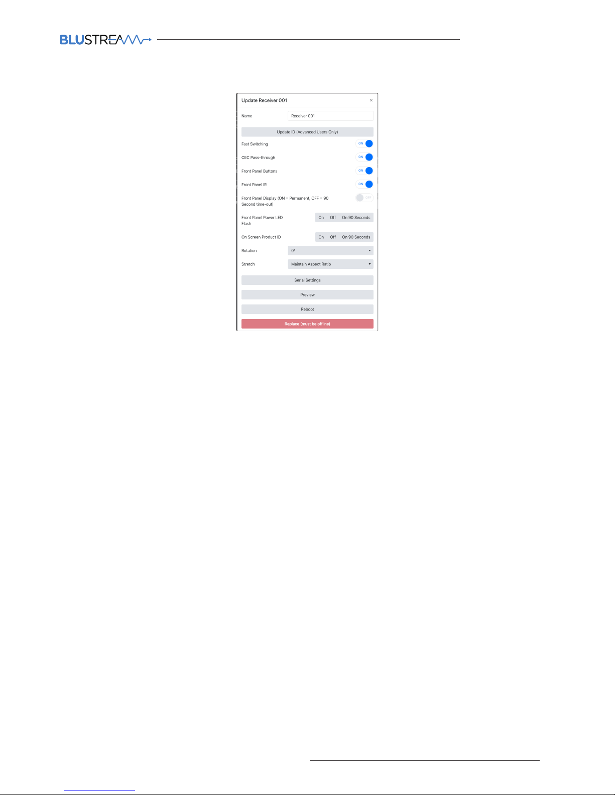
Web-GUI - Receivers - Actions
The 'Actions' button allows for
advanced features of the Receiver to
be accessed and configured.
1. Name - can be amended by entering a name into the free-form text box. Please note: this is limited to 16
characters in length, and some special characters may not be supported.
2. Update ID - the ID is defaulted to the last 3 digits of the device IP address i.e. Receiver ID 3 is assigned an IP
address of 169.254.6.3. Update ID allows you to amend the ID of the unit (not recommended).
3. Fast Switching - switches the video first, with the audio, IR, RS-232, USB / KVM all switched aer. Please note:
whilst video feed may switch faster, other parts of the feed (i.e. audio, IR etc) will take slightly longer to catch up.
4. CEC Pass-through (On / O) - allows for CEC (Consumer Electronic Command) to be sent via the Multicast
system to/from the display connected to the Receiver. Please note: CEC must also be enabled on the
Transmitter.
5. Front Panel Buttons (On / O) - the Channel buttons on the front of each Receiver can be disabled to stop
unwanted switching or manual configuration once the Receiver have been configured.
6. Front Panel IR (On / O) - enables or disables the Receiver from accepting IR commands to change source.
7. On Screen Product ID (On / O / 90 Seconds) - turn On / O the On Screen Product ID. Toggling the On Screen
Product ID On shows the ID (i.e. ID 001) of the Receiver overlayed on the display connected to the device. If 90
Seconds is selected, the OSD displays for 90 seconds. Toggling On Screen Product ID O removes the OSD.
8. Front Panel Power LED Flash (On / O / On 90 Seconds) - will flash the power LED on the front panel of the
Receiver to help identify the device. Options are to flash the power light continuously, or flash the LED for 90
seconds. Please note: the front panel LED's will time-out aer 90 seconds.
9. Front Panel Display (On / 90 Seconds) - use this to enable / disable the LED display on the front of the
Receiver. The front panel display will automatically time-out aer 90 seconds.
10. Rotation - rotate the image by: 0, 90, 180 and 270 degrees.
11. Stretch - re-sizes the image to 'Stretch' to the aspect of the display, or 'Maintain Aspect Ratio' of the source
device.
12. Serial Settings - enable serial 'Guest Mode' and set the serial port settings for the device (i.e. Baud Rate, etc).
13. Preview - displays a pop-up window with live screen grab of the source device connected to the Receiver.
14. Reboot - reboots the Receiver.
15. Replace - used to replace an oline Receiver. Please note: the unit to be replaced must be oline for this feature
to be utilised, and the new Receiver must be a factory default unit with IP address: 169.254.100.254.
16. Remove from Project - removes the Receiver from the project. This does not factory reset the Receiver.
17. Factory Reset - restores the Receiver to it's original default settings and sets the default IP address.
Page 24
ACM200 USER MANUAL
24
www.blustream.co.uk / www.blustream.com.au
Web-GUI - Receivers - Actions - Scaling / OSD Help
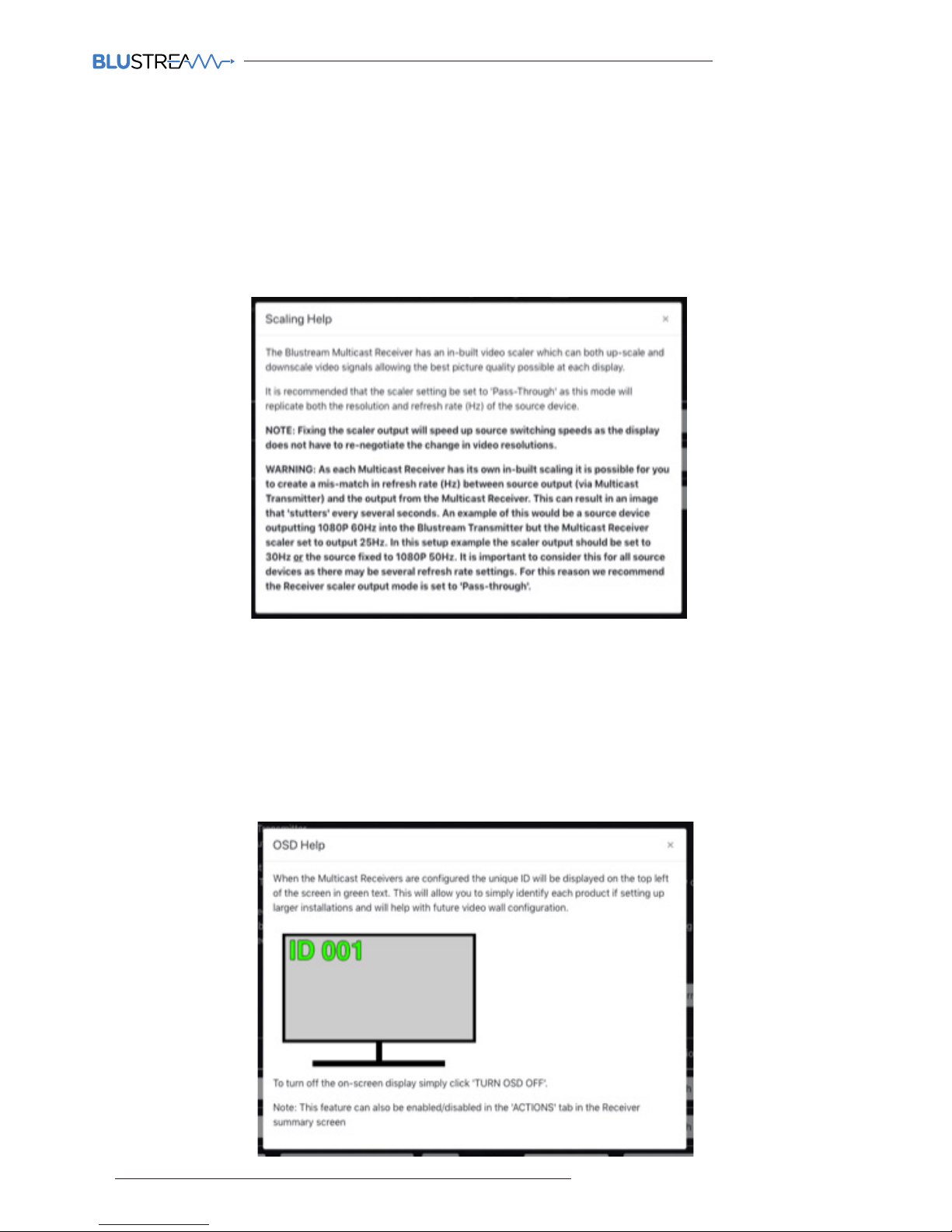
During the Set-up Wizard process there are a number of included Help Guides designed to give some basic
information to assist with attaining the correct settings for the system.
Scaling Help:
The Multicast Receiver has an in-built scaler which allows each display to playback its optimal quality video. Where
other methods of HDMI distribution will take a single resolution to all screens, the Multicast Receiver allows for
a 4K with HDR, 4K with no HDR, 1080p or 720p to individual screens using this feature. See 'Scaling Help' pop-up
information below:
Please note: it is possible to create a frame rate mis-match in the source signal by using a scaler setting from the
Multicast Receiver that des not match i.e. source frame rate is 60Hz and the scaler set to 50Hz. This can result in
image stutter. For this reason we recommend the Receiver scaler output to be set to 'Pass-through' where there are
multiple refresh rates within a system.
OSD Help:
In some parts of the ACM200 Web-GUI, there is an option to display an OSD (On Screen Display) for assistance with
the configuration of screens / Receivers, especially within a Video Wall array. See 'OSD Help' pop-up information
below:
Page 25
ACM200 USER MANUAL
25
contact [email protected] / [email protected]
Web-GUI - Fixed Signal Routing
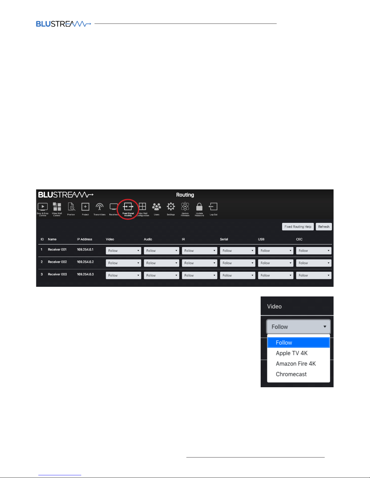
The ACM200 is capable of advanced independent routing of the following signals via the Multicast system:
• Video
• Audio
• Infrared (IR)
• RS-232
• USB / KVM
• CEC (Consumer Electronic Command)
This allows each signal to be fixed from one Multicast device to another and not be aected by standard video
switching. This can be useful for IR, CEC or RS-232 control of devices in the field using the Multicast system to extend
control commands from a third party control solution, or a manufacturers IR remote control.
Please note: with the exception of IR and RS-232, routing can only be fixed from a Receiver to a Transmitter.
Although routing can only be set up one way, the communication is bi-directional between the two devices. For
routing IR or RS-232 between 2x Transmitter units, please see pages 19 and 20.
By default, the routing of: Video, Audio, IR, Serial, USB and CEC will automatically
follow the Transmitter selection of the Receiver unit.
To select a fixed route, use the drop down box for each of the individual signals /
Receivers to fix a route.
Once an ACM200 has been added into a Multicast system, the IR switching control
abilities (not IR pass-through) and the front panel CH buttons of the Multicast
Receivers are enabled by default. This is disabled from the Actions function
contained within the Receiver summary page - see page 23.
Routing can be cleared by selecting 'Follow' at any point from the web-GUI. More
information on Fixed Routing can be found by clicking 'Fixed Routing Help'.
It is possible to alter the fixed signal routing from a third party control system. For advanced routing commands
please refer to the API section at the rear of this manual.
Page 26
ACM200 USER MANUAL
26
www.blustream.co.uk / www.blustream.com.au
Fixed Routed Audio
The ACM200 allows for the audio component of a HDMI signal to be routed independently throughout the
Blustream Multicast system. Under normal operation the embedded audio within a HDMI signal will be distributed
with the associated video signal from Transmitter to Receiver/s.
The fixed audio routing capabilities of the ACM200 allow for the audio track from one source to be embedded onto
another Transmitters video stream.
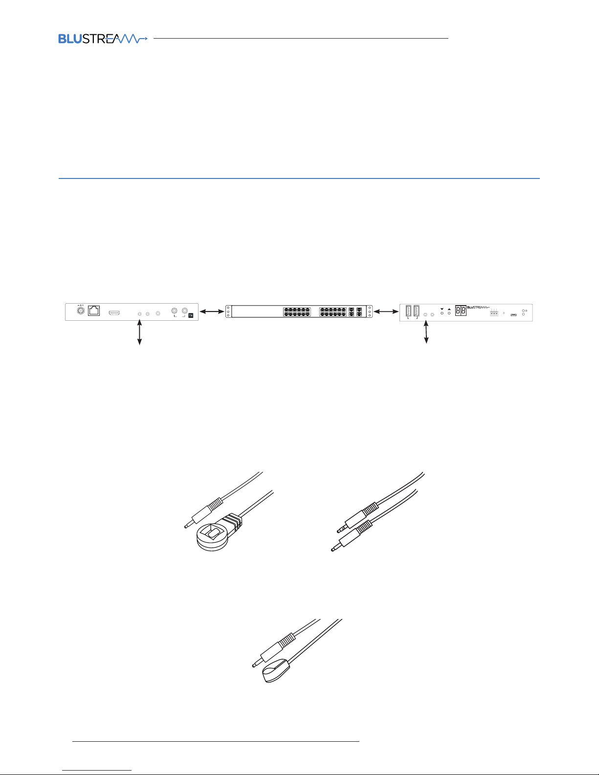
Connections:
The third party control processor IR, or Blustream IR receiver, is connected to the IR RX socket on the Multicast
Transmitter or Receiver.
Please note: You must use Blustream 5V IRR Receiver or Blustream IRCAB (3.5mm stereo to mono 12V to 5V IR
converter cable). Blustream Infrared products are all 5V and NOT compatible with alternative manufacturers
Infrared solutions.
Fixed Routed IR
The fixed IR routing feature allows a fixed bi-directional IR link between 2x Multicast devices. The IR signal is only
routed between configured RX to TX, or TX to TX. This can be useful for sending IR from a centrally located third
party control solution (ELAN, Control4, RTi, Savant etc) and using the Blustream Multicast system as a method of
extending IR out to a display or another product in the system. The IR link is bi-directional so can also be sent back
the opposite way at the same time.
The Blustream 5V IRE1 Emitter is connected to the IR OUT socket on the Multicast Transmitter or Receiver.
The Blustream IRE1 & IRE2 Emitters are designed for discrete IR control of hardware.
(IRE2 - Dual Eye Emitter sold separately)
IP200UHD-RX
MULTICAST UHD
LINK
RS-232
CH
CH SELECT
Rx
Tx
Gnd
OUT
IN
IR
IR
1 USB 2
UPDATE
Third party control system
i.e. - Control4, ELAN, RTi etc.
IR
IR
IP200UHD-RX
MULTICAST UHD
LINK
RS-232
CH
CH SELECT
Rx
Tx
Gnd
OUT
OUT
IN
IN
IR
IR
IR
IR
1 USB 2
LINK
IP200UHD-TX
UPDATE
UPDATE
RS-232
Rx
Tx
Gnd
MULTICAST UHD
CH
CH SELECT
USB
LAN / PoE
LAN / PoE
HDMI IN
HDMI OUT
LOOP OUT
L / R
DC IN
24~56V
DC IN
24~56V
AUDIO
IN
L / R
To display device
Page 27
ACM200 USER MANUAL
27
contact [email protected] / [email protected]
Fixed Routed USB / KVM
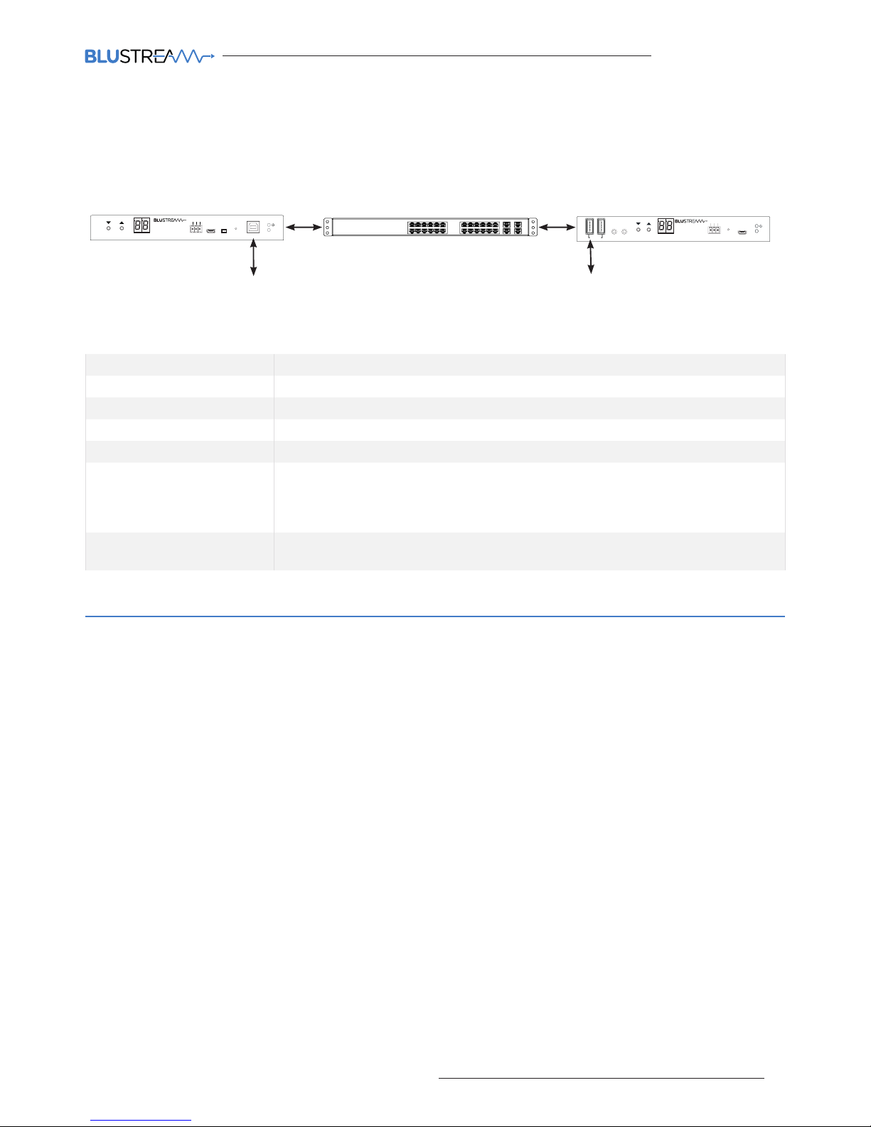
The fixed USB routing feature allows a fixed USB link between a Multicast Receiver/s and a Transmitter. This can be
useful for sending KVM signals between a users position to a centrally located PC, server, CCTV DVR / NVR etc.
IP200UHD-RX
MULTICAST UHD
LINK
RS-232
CH
CH SELECT
Rx
Tx
Gnd
OUT
IN
IR
IR
1 USB 2
UPDATE
PC, server, CCTV NVR / DVR etc
USB
USB
IP200UHD-RX
MULTICAST UHD
LINK
RS-232
CH
CH SELECT
Rx
Tx
Gnd
OUT
IN
IR
IR
1 USB 2
LINK
IP200UHD-TX
UPDATE
UPDATE
RS-232
Rx
Tx
Gnd
MULTICAST UHD
CH
CH SELECT
USB
Keyboard / mouse
USB Specification USB2.0
Extension Over IP, Hybrid redirection technology
Distance 100m
Distance Ext. via Ethernet switch hub
Max Downstream Devices 5
Topology 1 to 1
1 to many exclusively (USBoIP)
1 to many simultaneously but limited number of USB devices (USBoIP)*
1 to many simultaneously Keyboard / Mouse (K/MoIP)
USB R/W Performance * R: 69.6 Mbps
W: 62.4 Mbps
USB Specifications:
* Benchmark Reference: Read / Write USB to SATA HD without Multicast system R: 161.6 Mbps / W: 161.6 Mbps
Fixed Routed CEC
CEC or Consumer Electronic Command is a HDMI embedded control protocol that allows for commands to be sent
from one HDMI device to another for simple actions such as: Power, Volume etc.
The Blustream Multicast system allows for the CEC channel within the HDMI link between two products (source and
sink) to communicate with eachother using the CEC protocol.
CEC must be enabled (this is sometimes referred to as 'HDMI Control') on both the source device and the display
device in order for the Multicast system to communicate the CEC commands over the Multicast link.
Please note: the Blustream Multicast system will only transport the CEC protocol transparently. It is advisable to
ensure that the source and sink devices will communicate eectively before committing to this control type with
Multicast. Should an issue be experienced with CEC communication between the source and sink directly, this will
be mirrored when sending through the Multicast system.
Page 28
ACM200 USER MANUAL
28
www.blustream.co.uk / www.blustream.com.au
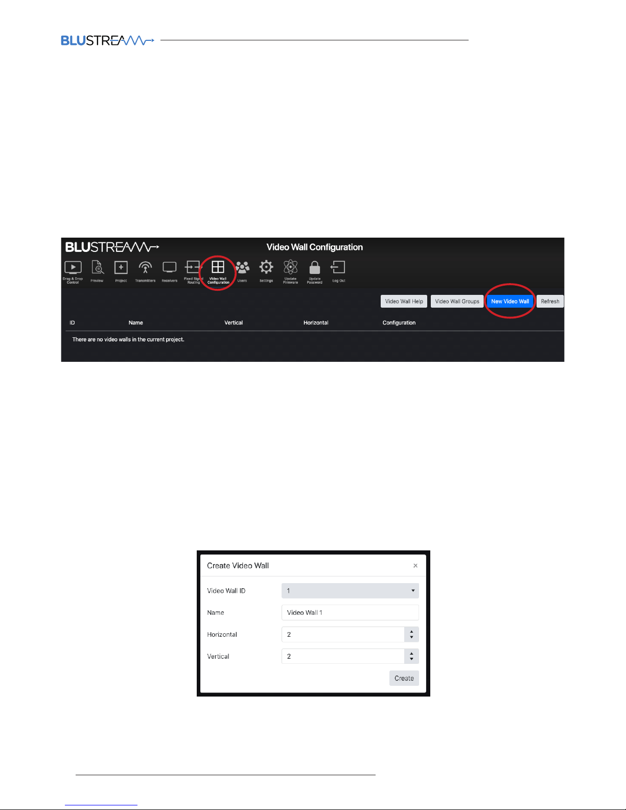
Web-GUI - New Video Wall Configuration
Blustream Multicast Receivers can be configured to be part of a Video Wall array within the ACM200. Any Multicast
system can contain up to 9x Video Wall arrays of diering shapes and sizes. Ranging from 1x2 up to 9x9. Each Video
Wall set-up will include the following:
Video wall creation - the allocation of Multicast Receivers to be part of a Video Wall display (number of screens
horizontally and vertically, assigning of Multicast Receivers to each area of the Video Wall etc)
Configuration - individual configurations of screens within a Video Wall. An example of a configuration would
be all screens assigned as a single Video Wall, all screens configured as individual displays, multiple Video Walls
configured within a larger Video Wall (Video Wall groups – see below).
Groups - a Video Wall group is the 'Grouping' of Multicast Receivers within a Video Wall allowing simplified source
selection and configuration recall of more than one Multicast Receiver at the same time.
Options on this page include:
1. Video Wall Help: help with creating a Video Wall array can be found by clicking this button.
2. Video Wall Groups: this option will not be used until a Video Wall array has been created. Please see page 31
for this option once a Video Wall has been configured.
3. New Video Wall: configure a new Video Wall array. See below for the creation of a new Video Wall array.
Creating a New Video Wall:
The Multicast Receivers that will be used for the Video Wall should have been configured as individual Receivers
before proceeding past this point. It is good practice to have already named the Multicast Receivers for ease of
configuration i.e. “Video Wall 1 - Top Le”.
Enter the relevant information into the pop-up window to name and select the number of panels both horizontally
and vertically within the Video Wall array. Once the correct information has been inserted onto the screen, select
'Create' to create the Video Wall array template within the ACM200.
Page 29
ACM200 USER MANUAL
29
contact [email protected] / [email protected]
Web-GUI - New Video Wall Configuration - continued...
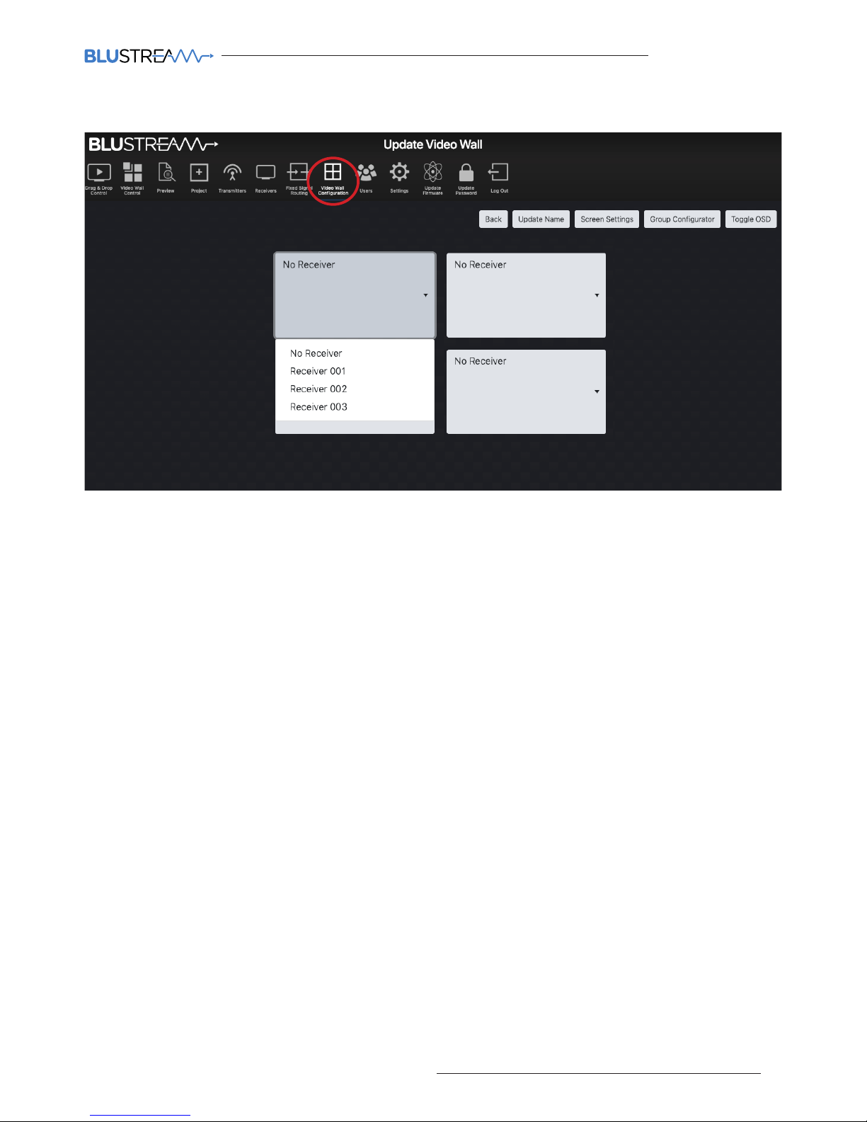
The menu page for the new Video Wall array has the following options:
1. Back - returns to the previous page for creating a new Video Wall.
2. Update Name - amend the name given to the Video Wall array.
3. Screen Settings - adjustment of bezel / gap compensation of the screens being used. See next page for more
details on Bezel settings.
4. Group Configurator - there are options to be able to create multiple configurations (or 'presets') for each
Video Wall array. The grouping / preset allows for the Video Wall to be deployed in multiple ways i.e. grouping
dierent numbers of screens together to create dierent sized walls within a single array. See page 31 for more
information.
5. Toggle OSD - turn On / O the OSD (On Screen Display). Toggling the OSD On will show the ID number (i.e. ID
001) of the Multicast Receiver on each display as an overlay to the media being distributed. Toggling OSD O
removes the OSD. This allows easier identification of displays within a Video Wall during configuration and setup.
Display / Receiver Assign (drop down boxes):
The ACM200 will create a visual representation of the Video Wall on the page. Use the drop down arrows for each
screen to select the relevant Multicast Receiver on the Video Wall array.
Page 30
ACM200 USER MANUAL
30
www.blustream.co.uk / www.blustream.com.au
Web-GUI - New Video Wall Configuration - Bezel Settings
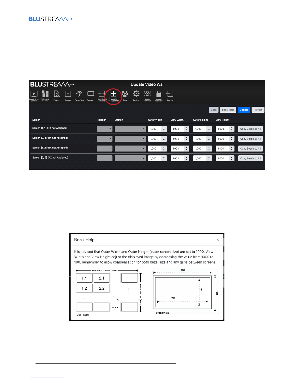
This page allows for the compensation for the size of each screen bezel within the Video Wall, or alternatively for any
gaps inbetween screens. By default, the Multicast system will insert the bezels of the Video Wall screens “inbetween”
the overall image (splitting the image). This will mean that the bezels of the screens do not sit “over” any part of the
image. By adjusting the Outer Width (OW) vs View Width (VW), and the Outer Height (OH) vs View Height (VH), the
screen bezels can be adjusted to sit “on top” of the image that is being displayed.
All units are by default: 1,000 - this is an arbitary number. To compensate for bezel size of the screens being used,
reduce the View Width and View Height accordingly to compensate for the size of the bezels. Once the outcome of
the corrections required has been obtained, the 'Copy Bezels to All' button can be used to copy the settings to each
display. Click 'Update' to confirm settings, and 'Back' to return to the previous Update Video Wall screen.
The 'Bezel Help' button opens a pop-up window with guidance to the correction and adjustment of these settings.
Page 31
ACM200 USER MANUAL
31
contact [email protected] / [email protected]
Web-GUI - New Video Wall Configuration - Group Configurator
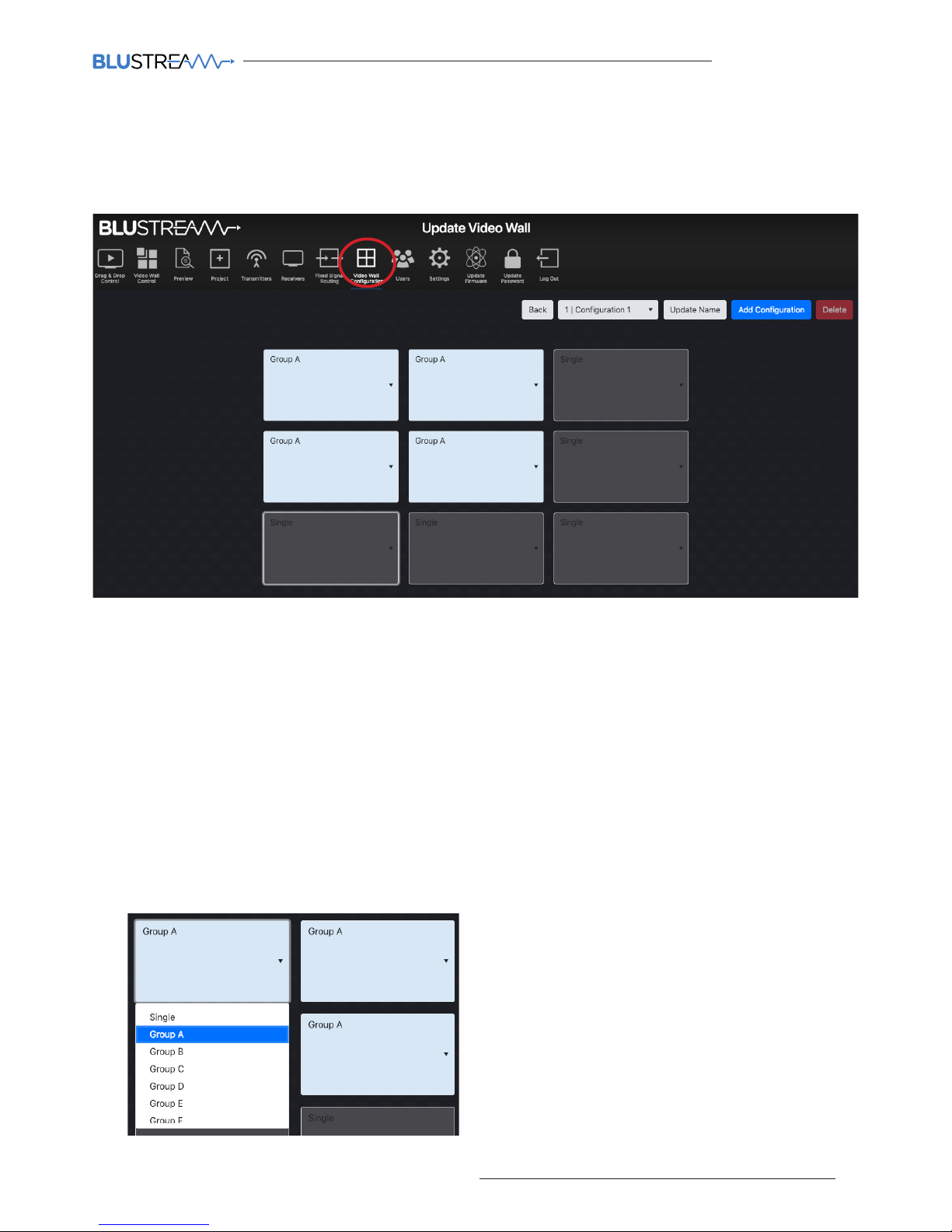
Once the Video Wall array has been created, it can be configured for dierent display options. The Video Wall
Configurator allows for presets to be created for deploying the Video Wall to adjust for dierent groups of images
across the array. Click the 'Group Configurator' button from the Update Video Wall screen.
Options within this menu as follows:
1. Back - navigates back to the Update Video Wall page without making any changes to the set-up.
2. Configuration Dropdown - move between dierent configurations (or presets) previously set-up for the Video
Wall array. By default, 'Configuration 1' will be inserted for a Video Wall being created and configured for the first
time.
3. Update Name - set the name of the configuration (preset) i.e. ‘Single Screens’ or ‘Video Wall’. By default,
configuration / preset names will be set as 'Configuration 1, 2, 3...' until changed.
4. Add Configuration - adds a new configuration (preset) for the selected Video Wall.
5. Delete - removes the currently selected configuration.
Group Assign:
Grouping allows for the Video Wall to be deployed in multiple ways i.e. creating dierent sized Video Walls within a
larger Video Wall array. Use the dropdown selection for each screen to create a Group within the Video Wall:
See next page for further explanation on how a larger
Video Wall array can have multiple Groups configured
within.
Page 32
ACM200 USER MANUAL
32
www.blustream.co.uk / www.blustream.com.au
Web-GUI - New Video Wall Configuration - Group Configurator
For example: a 3x3 Video Wall array can have multiple configurations (presets):
• For displaying 9x dierent source media streams - so that all screens work independently with each individual
screen showing a single source - not grouped (leave all dropdowns as 'Single').
• As a 3x3 Video Wall - displaying one source media stream across all 9 screens (all screens need to be selected as
'Group A').
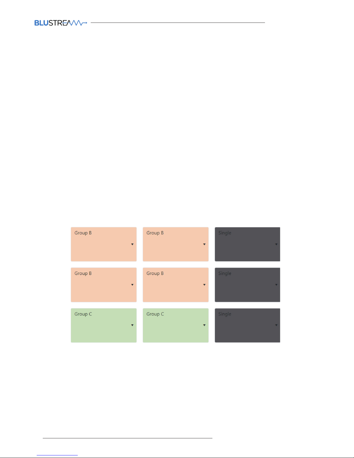
• For displaying a 2x2 Video Wall image within the overall 3x3 Video Wall array. This can have 4x dierent options:
• With the 2x2 in the top le of the 3x3, with 5x individual screens to the right and bottom (select the 2x2 in
the top le as Group A with other screens set as 'Single') - see example below...
• With the 2x2 in the top right of the 3x3, with 5x individual screens to the le and bottom (select the 2x2 in
the top right as Group A with other screens set as 'Single').
• With the 2x2 in the bottom le of the 3x3, with 5x individual screens to the right and top (select the 2x2 in
the bottom le as Group A with other screens set as 'Single').
• With the 2x2 in the bottom right of the 3x3, with 5x individual screens to the le and top (select the 2x2 in
the bottom right as Group A with other screens set as 'Single').
With the above example, there would be the need to create 6 dierent configurations for the Video Wall array,
allocating the grouped screens to a Group using the selection dropdown. The Configurations / Groups can be
renamed as required using the ‘Update Name’ option in the Group Configuration screen.
Additional configurations can be created with screens assigned as groups. This allows multiple video sources to be
viewed at the same time and will appear as a Video Wall within a Video Wall. The below example has two dierent
sized Video Walls inside a 3x3 array. This configuration contains 2 groups:
Page 33
ACM200 USER MANUAL
33
contact [email protected] / [email protected]
Web-GUI - Existing Video Wall Configuration
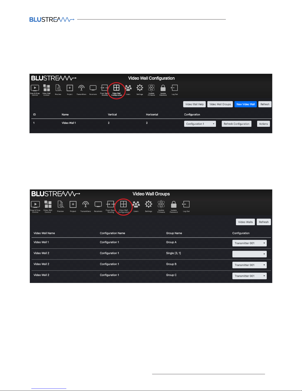
Once a Video Wall has been created, named accordingly, and groups / presets have been assigned, the configured
Video Wall can be viewed from the main Video Wall Configuration page. The dropdown Configuration box allows
for the Configuration of the Video Wall to be changed accordingly. The 'Refresh Configuration' button refreshes
configuration on screen when using a third party control system to check the command has worked when testing.
To amend an existing Video Wall, click the 'Actions' button for the Video Wall that needs to be updated. Click the
button marked 'Update Settings' button to return to the Update Video Wall page as shown on page 29. You can also
'Remove' a Video Wall from the system. Please note: once a Video Wall has been removed, it cannot be undone.
Configurations / presets that have been designed within the system will now appear within the Video Wall Groups
page. The Video Wall Configuration page allows for a group to be switched:
Using the dropdown 'Configuration' selection, any Transmitter can be chosen for each of the dierent available
Groups across all defined Video Walls. Where the Video Wall is switched between dierent Configurations (where
single or multiple Groups may be available) these can be switched from the same page. In the above example,
Video Wall 2, in Configuration 1, has two dierent Groups of screens - these Groups can be switched by using the
dropdown menus alongside each. The single screens within Configuration 1 can be switched simultaneously to the
same source by using the dropdown, however, if it is required to watch individual sources then use the Video Wall
Control page.
The 'Refresh' button refeshes the current page and the current Configuration of the Video Wall array being
displayed. This is particularly helpful when testing Video Wall configuration commands from a third party control
system.
Please see the advanced API commands for use with third party control systems for Video Wall control,
Configuration switching and Group selection on page 46 of this guide.
Page 34

ACM200 USER MANUAL
34
www.blustream.co.uk / www.blustream.com.au
Web-GUI - Users
The ACM200 has the ability for individual Users to log into the web-GUI of the Multicast system and access individual
parts / zones of the system, for full control of the entire Multicast system, or for simple control of which source is
being watched in selected locations only. For assistance setting up new Users, click on the button marked 'Users
Help'.
To set-up a new User, click 'New User' at the top of the screen:
Enter the new User credentials into the window that appears and click 'Create' once completed:
The new User will then appear in the Users menu page ready for access / permissions to be configured:
Page 35
ACM200 USER MANUAL
35
contact [email protected] / [email protected]
Web-GUI - Users - continued...
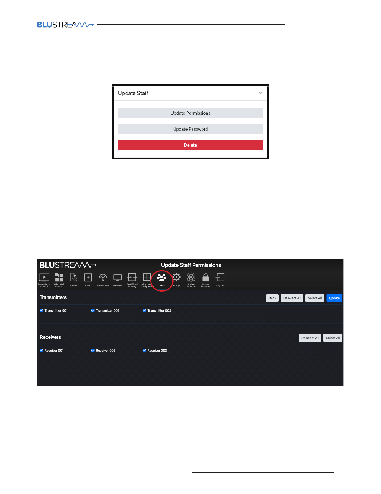
To select individual User permissions, update the User password, or to remove the User from the Multicast system,
click the 'Actions' button.
The Permissions option gives access to select which Transmitters or Receivers the User can see within their control
pages (Drag & Drop Control, and Video Wall Control). With all boxes checked next to each Transmitter or Receiver,
the User can preview and switch across the entire system. If the User is only to be able to control one screen /
receiver, then uncheck all other Receivers. Likewise, if the User is not to be given access to one (or more) source
devices, these Transmitters should be unchecked.
IMPORTANT: where there is a Video Wall array in the Multicast system, a User will need access to ALL associated
Receivers to be able to gain switching control of the Video Wall. If the User does not have access to all Receivers, the
Video Wall will not appear in the Video Wall Control page.
Once the User permissions have been selected, click 'Update' to apply the settings.
Please note: in order to stop non-secure access to the web interface (i.e. with no password), the 'Guest' account
must be deleted aer a new user with access to the sources / screens applicable set-up. This way, any User of the
system is required to enter a password to gain switching control of the system.
Page 36
ACM200 USER MANUAL
36
www.blustream.co.uk / www.blustream.com.au
Web-GUI - Settings
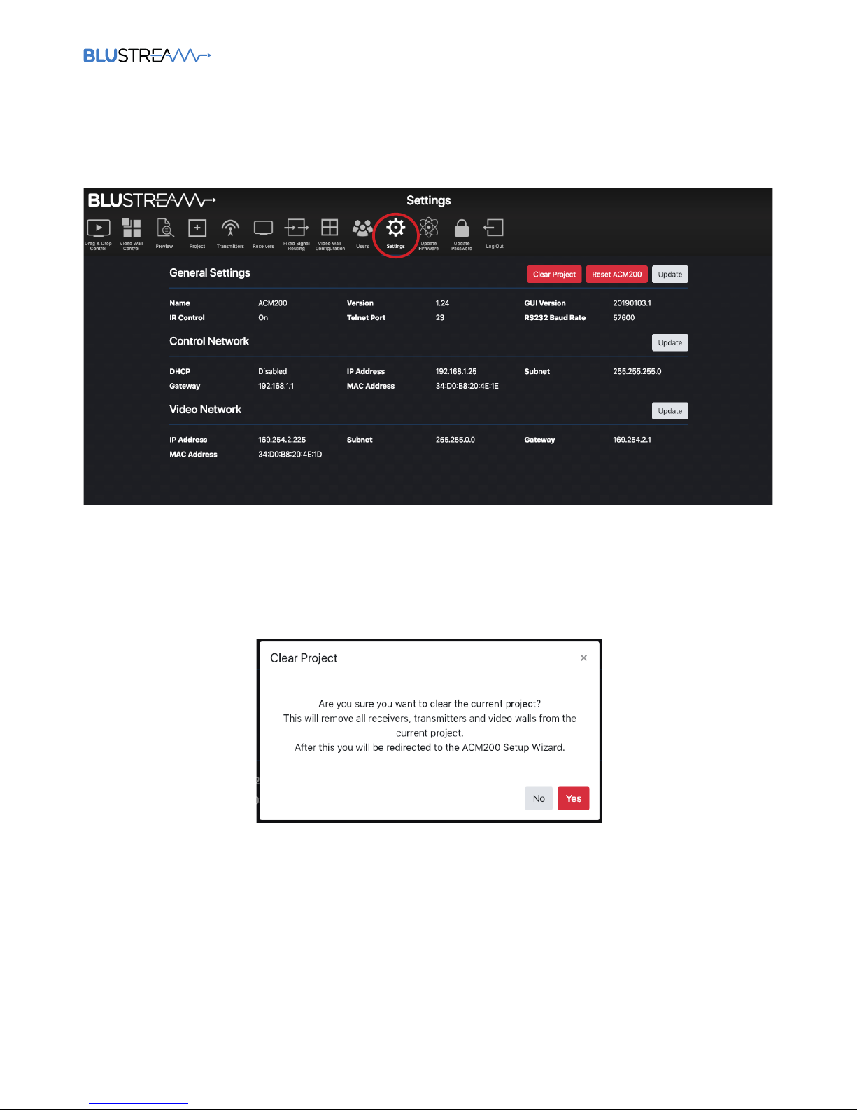
The Settings page of the ACM200 will provide an overview of the general settings, and control / video network
settings of the unit with the ability to amend and update the unit accordingly.
The 'Clear Project' removes all Transmitters, Receivers, Video Walls and Users that have been created from the
current project file contained within the ACM200. Confirm by selecting 'Yes'.
Please note: the New Project Setup Wizard will appear aer using the 'Clear Project' function. Should a project save
file not have been created prior to clearing the project, it is not possible to restore the system aer this point.
Page 37
ACM200 USER MANUAL
37
contact [email protected] / [email protected]
Web-GUI - Settings - continued...
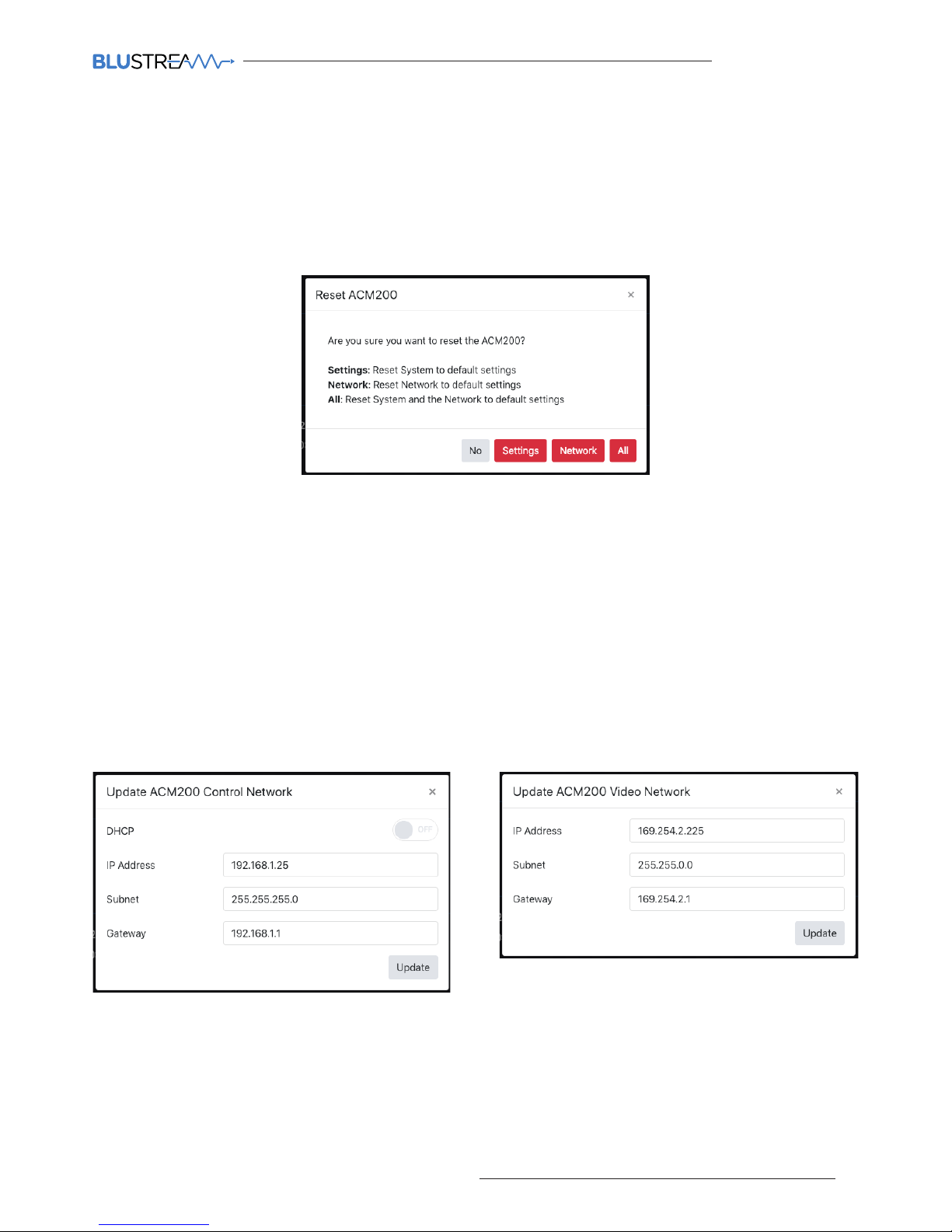
The 'Reset ACM200' option allows for the following:
1. Reset System to factory default (excludes Network settings)
2. Reset Network to default settings (excludes System settings)
3. Reset ALL System and Network settings back to factory default
Under general settings, the 'Update' option allows for the following:
1. Turn On / O IR control to enable / disable the IR input of the ACM200 from accepting IR commands from a third
party control solution.
2. Update the Telnet port number that the Control port of the ACM200 communicates through. The default port
number used is port 23 which will be used for all oicial Blustream third party control drivers.
3. Update the RS-232 Baud Rate of the DB9 connection of the ACM200 to suit a third party control processor. The
default Baud Rate used is: 57600.
The IP addresses of the two RJ45 ports on the ACM200 can be updated with individual IP, Subnet and Gateway
addresses. Use the 'Update' button for either the Control Network or Video Network to update the information for
the ports required. The Control Port can be set to DHCP by selecting 'On':
IMPORTANT: Amending the Video Network IP Address out of the 169.254.x.x range will stop communication
between the ACM200 and the Multicast Transmitters and Receivers that have been pre-configured.
Page 38
ACM200 USER MANUAL
38
www.blustream.co.uk / www.blustream.com.au
Web-GUI - Update Firmware
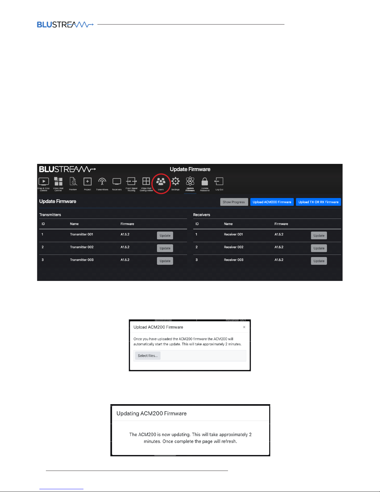
The Update Firmware page allows for the firmware updating of:
• The ACM200 unit
• Multicast Transmitter and Receiver units
Please note: firmware packages for the ACM200, Multicast Transmitter and Receiver products are individual. It is
recommended that firmware updating is only completed from a desktop or laptop PC that is hard-wired into the
network.
Updating the ACM200:
Download the ACM200 Firmware file (.bin) from the Blustream website to your computer.
Click on the buttom marked 'Upload ACM200 Firmware'
Select the [ACM200].bin file already downloaded to your computer for the ACM200. The file will automatically
upload to the ACM200 which takes approximately 2 minutes to complete. The page refreshes to the Drag & Drop
page once complete.
Page 39
ACM200 USER MANUAL
39
contact [email protected] / [email protected]
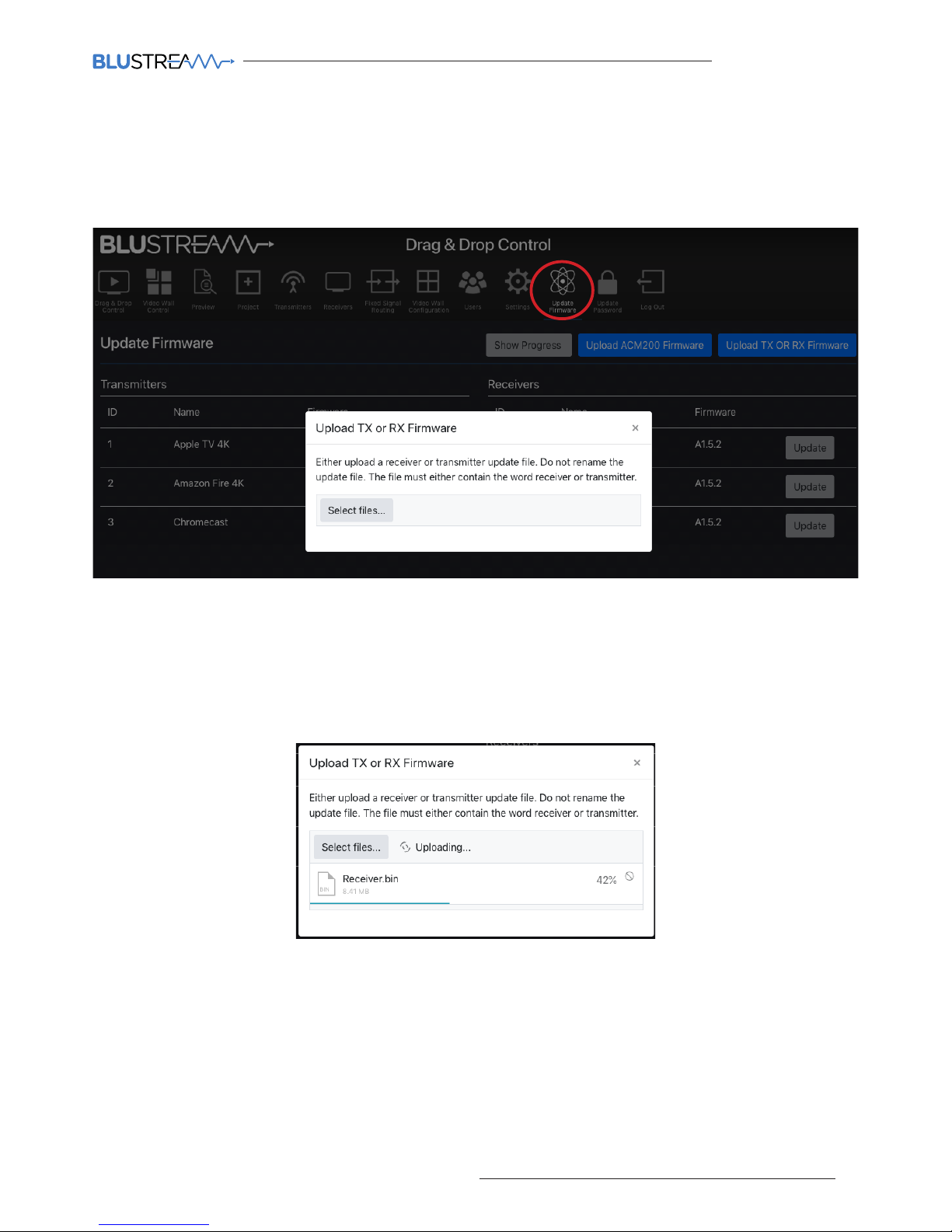
The Update Firmware page is also used for firmware upgrading the firmware of Blustream Transmitters or Receivers.
The most current firmware version for the Multicast Transmitters and Receivers can be downloaded from the
Blustream website.
To upload the firmware files, click the button marked 'Upload TX or RX Firmware', then 'Select Files'. Once the
correct firmware (.bin) file has been selected from the computer, the firmware will upload to the ACM200.
Please note: this part of the upgrade does not upload the firmware into the TX or RX units, it only uploads to the
ACM200 ready for deployment to the TX or RX.
IMPORTANT: Do not close or navigate away from the upload whilst in progress to avoid firmware data being lost
during transfer to the ACM200.
Web-GUI - Update Firmware - continued...
Page 40
ACM200 USER MANUAL
40
www.blustream.co.uk / www.blustream.com.au
Web-GUI - Update Firmware - continued...
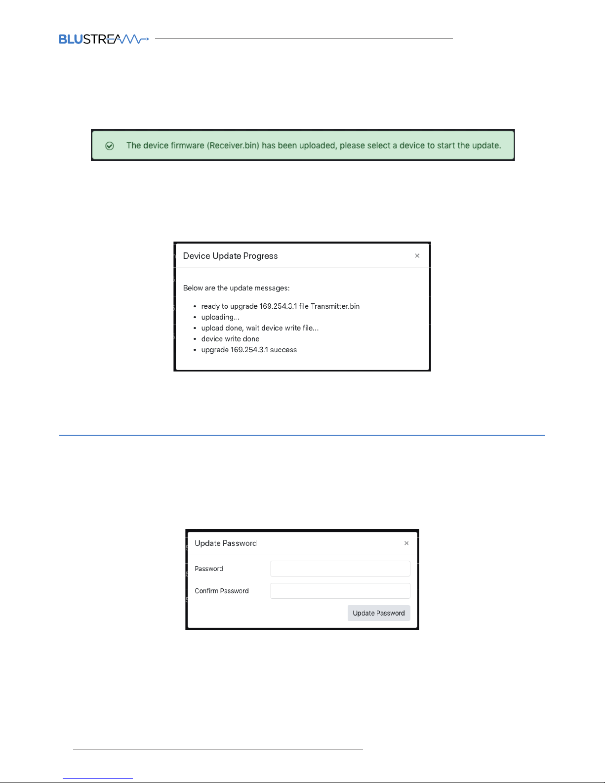
On completion of the firmware files being uploaded to the ACM200, a notification will appear on screen to feedback
the success of the upload:
To complete the upgrade of the firmware of either the Multicast Transmitter, or for Receiver units, click the
buttom marked 'Update' next to the relevant Transmitter or Receiver. Please note: it is only possible to update
Transmitters, or Receivers at one time. The firmware upgrade process will then begin:
Web-GUI - Update Admin Password
The Admin password for the ACM200 can be updated to an alpha-numeric password by inserting the new
credentials in this pop-up menu option. Click 'Update Password' to confirm:
IMPORTANT: Once the Admin password has been changed, it cannot be recovered by the User. If the Admin
password is forgotten or lost, please contact a member of the Blustream Technical Support team who will be able
to assist in the recovery of the Admin rights of the unit. See email addresses below:
IMPORTANT: Do not disconnect the ACM200 or TX / RX units whilst in the upgrade process is in progress to avoid
firmware data being lost during transfer to the individual Transmitter / Receiver devices.
Page 41

ACM200 USER MANUAL
41
contact [email protected] / [email protected]
RS-232 (Serial) Routing
The Multicast system features two ways of managing RS-232 command signals:
Type 1 - Fixed Routing:
A static fixed routing for distributing two-way RS-232 commands between a Multicast Transmitter to one or multiple
Receivers (Fixed Routing). Fixed routing can be le static between two or more products as a permanent connection
for the transfer of RS-232 control data, this is configured using the Fixed Routing menu of the ACM200.
Type 2 - Guest Mode:
Allows the RS-232 connection of a device to be sent over the IP network (IP / RS-232 command in, to RS-232 out).
Type 2 Guest Mode gives third party control systems the ability to send an RS-232 or IP command to the ACM200
and an RS-232 command to be sent out of a Receiver or Transmitter as a result. This IP to RS-232 signalling, allows
the third party control system to have control of as many RS-232 devices as there are Receivers and Transmitters,
from the network connection to the ACM200.
There are two ways of enabling Type 2 - Guest Mode:
1. Using the ACM200 web-GUI. See page 20 for enabling Guest Mode on a Tranmsitter and page 23 for enabling
Guest Mode on a Receiver unit.
2. Via the command set as detailed below. The command to configure the connection is: IN/OUT xxx SG ON
RS-232 Guest Mode Connection from a Third Party Control System:
When using Guest Mode on multiple devices within a system, we would recommend turning Guest Mode on and
o when required. This is because a serial command being sent into the ACM200 will be passed to ALL devices that
have Guest Mode enabled.
1. To open a Guest Mode connection between the ACM200 and an IPxxxUHD-TX or RX unit the following
command must be sent via IP or RS-232:
INxxxGUEST Connect to TX xxx in Guest Mode from the ACM200
OUTxxxGUEST Connect to RX xxx in Guest Mode from the ACM200
Example: Transmitter ten is ID 010, meaning 'IN010GUEST' will allow bi-directional Serial / IP
commands to be sent between the ACM200 and Transmitter 10.
2. Once a connection is established, any characters that are sent from the ACM200 will be transmitted to the
connected Transmitter or Receiver, and vice versa.
3. To close the connection send the command: ACMCLOSEGUEST
Please note: When the ACM200 is in GUEST MODE the web-GUI is disabled.
Page 42

ACM200 USER MANUAL
42
www.blustream.co.uk / www.blustream.com.au
Specifications
Package Contents
ACM200
• Ethernet port: 2x LAN RJ45 connector (1x PoE support)
• RS-232 serial port: 1x DB-9 female
• RS-232 & I/O port: 1x 6-pin Phoenix connector (reserved for future use)
• IR input port: 1x 3.5mm stereo jack
• Dimensions (W x D x H ): 96mm x 110mm x 26mm
• Shipping weight (Kit): 0.6kg
• Operating temperature: 32°F to 104°F (0°C to 40°C)
• Storage temperature: -4°F to 140°F (-20°C to 60°C)
• 1 x ACM200
• 1 x IR control cable - 3.5mm to 3.5mm stereo to mono cable
• 1 x 6-pin phoenix connector
• 1 x Mounting kit
Maintenance
Clean this device with a so, dry cloth. Never use alcohol, paint thinner or benzene to clean this device.
Page 43

ACM200 USER MANUAL
43
contact [email protected] / [email protected]
RS-232 and Telnet Commands
The Blustream Multicast system can be controlled via serial and TCP/IP. Please refer to the RS-232 connections page
towards the start of this manual for settings and pin out. The following pages list all available serial commands for
the Multicast solution when using the ACM200.
Common Mistakes
• Carriage return – Some programs do not require the carriage return where as other will not work unless sent direct-
ly aer the string. In the case of some Terminal soware the token <CR> is used to execute a carriage return. Depending on the program you are using this token maybe dierent. Some other examples that other control systems deploy
include \r or 0D (in hex).
• Spaces – the ACM200 can work with our without spaces. It simply ignores them. It can also work with 0 to 4 digits.
eg: 1 is the same as 01, 001, 0001
- How the string should look is as follows OUT001FR002
- How the string may look if spaces are required by the control system: OUT{Space}001{Space}FR002
• Baud Rate or other serial protocol settings not correct
The following pages list the common API commands that will be required for third party control systems
Please note: the maximum number of Transmitters (yyy) and Receivers (xxx) = 762 devices (001-762)
- Receivers (outputs) = xxx
- Transmitters (inputs) = yyy
- Scaler Output = rr
- EDID Input settings = zz
- Baud Rate = br
- GPIO input/output ports = gg
For a full list of all API commands for the ACM200, please see separate Advanced Control Module API Document published on the Blustream website.
Blustream ACM200 commands and feedback
Blustream Infrared Commands
Blustream have created 16x input & 16x output IR commands allowing source selection of up to 16x IPxxxUHD-TX
Transmitters on up to 16x IPxxxUHD-RX Receivers. These are dierent to the source switching controls sent to a
Multicast Receiver.
For systems larger than 16x source devices (IPxxxUHD-TX), please use RS-232 or TCP/IP control.
For the complete database of Multicast IR commands, please visit the Blustream website page for any Multicast
devices, click on the "Drivers & Protocols" button, and navigate to the folder named "Multicast IR Control".
Page 44

ACM200 USER MANUAL
44
www.blustream.co.uk / www.blustream.com.au
COMMAND DESCRIPTION COMMAND RESPONSE
Set OUTPUT:xxx From INPUT:yyy (ALL signals routed) OUTxxxFRyyy Set output xxx From INPUT:yyy
Fix VIDEO OUTPUT:xxx From INPUT:yyy OUTxxxVFRyyy Set output video xxx From INPUT:yyy
Fix AUDIO OUTPUT:xxx From INPUT:yyy OUTxxxAFRyyy Set output audio xxx From INPUT:yyy
Fix IR OUTPUT:xxx From INPUT:yyy OUTxxxRFRyyy Set output IR xxx From INPUT:yyy
Fix RS232 OUTPUT:xxx From INPUT:yyy OUTxxxSFRyyy Set output RS232xxx From INPUT:yyy
Fix USB OUTPUT:xxx From INPUT:yyy OUTxxxUFRyyy Set output usb xxx From INPUT:yyy
Fix CEC OUTPUT:xxx From INPUT:yyy OUTxxxCFRyyy Set output cec xxx From INPUT:yyy
Set CEC OUTPUT:yyy ON or O OUTxxxCECON/OFF Set output xxx cec mode ON/OFF
Set OUTPUT:xxx Fast Switching On or O OUTxxxFASTON/OFF Set output xxx fast switching mode ON/OFF
Set OUTPUT:xxx HDR On or O OUTxxxHDRON/OFF Set output xxx hdr mode ON/OFF
Reboot Receiver
OUTxxxRB
Set output xxx reboot and apply all the new
config
Rotate Receiver Video Output
tt=0: clockwise 0 degree rotate
tt=90: clockwise 90 degree rotate
tt=180: clockwise 180 degree rotate
tt=270: clockwise 270 degree rotate
OUTxxxROTATEtt output xxx rotate tt degree
Stretch video Output (keep aspect ratio stretch to fit) OUTxxxSTRETCHON/
OFF
Set output xxx stretch ON/OFF
Switch Receiver (Output) between Matrix and Video Wall
mode
OUTxxxMODEMX/VW Set output xxx to matrix/video wall mode
Receiver HDCP management mode OUTxxxDBGON/OFF Set output xxx debug mode ON/OFF
Set Scaler Output Resolution
0:Bypass
1:2160p@30
2:2160p@24
3:1080p@50
4:1080p@60
5:1080i@50
6:1080i@60
7:720p@60
8:720p@50
9:1280x1024@60
10:1024x768@60
11:1360x768@60
12:1440x900@60
13:1680x1050@60
OUTxxxRESrr
Set output xxx resolution to bypass (=0)
Set output xxx resolution to 2160p@30(=1)
ETC
Single Receiver (output) status OUTxxxSTATUS (See status example at end of document)
Receiver (Output) Commands
Page 45

ACM200 USER MANUAL
45
contact [email protected] / [email protected]
Transmitter (Input) Commands
COMMAND DESCRIPTION COMMAND RESPONSE
Set CEC INPUT:yyy ON or O INyyyCECON/OFF Set input xxx cec mode ON/OFF
Set TX Audio source to HDMI audio INyyyAUDORG Set Audio source:xxx to audio select
hdmi
Set TX Audio source to Analog INyyyAUDANA Set Audio source:xxx audio select
analog
Set TX Audio source to Auto INyyyAUDAUTO Set Audio source:xxx audio select
auto
Reboot Transmitter
INyyyRB
Set output xxx reboot and apply all
the new config
Copy EDID Input yyy from Output xxx EDIDyyyCPxxx Copy outputxxx edid to input yyy
Set Input: yyy EDID To EDID:zz
zz=00: HDMI 1080p@60Hz, Audio 2CH PCM
zz=01: HDMI 1080p@60Hz, Audio 5.1CH PCM/DTS/ DOLBY
zz=02: HDMI 1080p@60Hz, Audio 7.1CH PCM/DTS/DOLBY/HD
zz=03: HDMI 1080i@60Hz, Audio 2CH PCM
zz=04: HDMI 1080i@60Hz, Audio 5.1CH PCM/DTS/DOLBY
zz=05: HDMI 1080i@60Hz, Audio 7.1CH PCM/DTS/DOLBY/HD
zz=06: HDMI 1080p@60Hz/3D, Audio 2CH PCM
zz=07: HDMI 1080p@60Hz/3D, Audio 5.1CH PCM/DTS/DOLBY
zz=08: HDMI 1080p@60Hz/3D, Audio 7.1CH PCM/DTS/DOLBY/
HD
zz=09: HDMI 4K@30Hz 4:4:4, Audio 2CH PCM
zz=10: HDMI 4K@30Hz 4:4:4, Audio 5.1CH DTS/DOLBY
zz=11: HDMI 4K@30Hz 4:4:4, Audio 7.1CH DTS/DOLBY/HD
zz=12: DVI 1280x1024@60Hz, Audio None
zz=13: DVI 1920x1080@60Hz, Audio None
zz=14: DVI 1920x1200@60Hz, Audio None
zz=15: HDMI 4K@30Hz 4:4:4, Audio 7.1CH(Default)
zz=16: HDMI 4K@60Hz 4:2:0, Audio 2CH PCM
zz=17: HDMI 4K@60Hz 4:2:0, Audio 5.1CH DTS/DOLBY
zz=18: HDMI 4K@60Hz 4:2:0, Audio 7.1CH DTS/DOLBY/HD
EDIDyyyDFzz
Set input yyy edid with default edid
zz
Single Transmitter (input) status
INyyySTATUS
(See status example at end of document)
Page 46
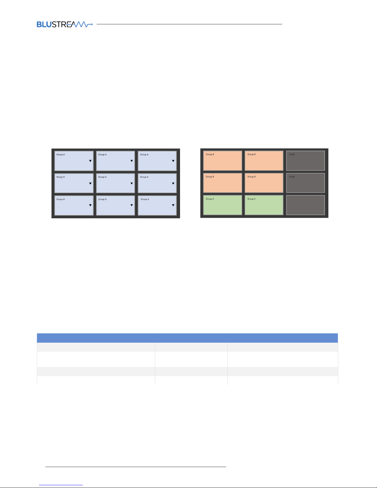
ACM200 USER MANUAL
46
www.blustream.co.uk / www.blustream.com.au
COMMAND DESCRIPTION COMMAND RESPONSE
Apply Config to Video Wall VW idx C cidx APPLY Apply config: Configuration cidx
Set Grouped Output from Single Source
INPUT:yyy
VW idx C cidx G gidx FR yyy [SUCCESS] Done
ALL video wall status VWSTATUS (See status example at end of document)
Single Video Wall status VWidxSTATUS (See status example at end of document)
Video wall configurations will be setup in the ACM200 Web GUI
Each video wall setup will include the following:
• Video wall creation = each Multicast system can include up to 9x separate video walls (01-09)
• Configuration = individual configurations of screens within a video wall. An example of a configuration would be all
screens assigned as a single video wall, all screens configured as individual displays, multiple video walls configured within a larger video wall (video wall groups – see below) (01-09)
• Groups = a video wall group is the ‘Grouping’ of Multicast receivers within a video wall allowing simplified source
selection and configuration recall of more than one Multicast Receiver at the same time (A-J)
Video Wall 1 Configuration 1 Video Wall 2 Configuration 2
Example of control commands:
• VW01C01APPLY (will apply video wall configuration 1 above to all Receivers)
• VW01C02APPLY (will apply video wall configuration 2 above to all Receivers)
• VW01C01GaFR002 (will apply video configuration 1 and switch all screens to Transmitter 002
• VW01C02GbFR006 (will apply video configuration 1 and switch group b screens [orange] to Transmitter 006
When recalling video wall configurations the following applies:
Characters:
idx = [01...09] - Video Wall Index / Number
cidx = [01...09] - Config Index / Number
gidx = [A...J] - Group Index / Number
Video Wall Commands
Page 47

ACM200 USER MANUAL
47
contact [email protected] / [email protected]
General ACM200 Commands
COMMAND DESCRIPTION COMMAND RESPONSE
Print all available commands of ACM200 HELP (See HELP summary at end)
Turn IR control port On or O IRON/OFF Set IR ON/OFF
Turn On Serial Guest Mode to Receiver (output)
(NOTE: This only puts the RX into Serial Guest
mode but doesn't open the connection. Please use
command below)
br =0: 300
br=1: 600
br=2:1200
br=3: 2400
br=4: 4800
br=5: 9600
br=6: 19200
br=7: 38400
br=8: 57600
br=9: 115200
bit= Data Bits + Parity + Stop Bits
Example: 8n1
Data Bits=[5...8], Parity=[n o e], Stop
Bits=[1..2]
OUTxxxSGON/OFF[br][bit] Set serial guest mode config done
Serial Guest Mode to Transmitter (input)
(details as above)
INxxxSGON/OFF[br][bit] Set serial guest mode config done
Start Serial Guest Mode To Output ooo OUT ooo GUEST (no feedback when in guest mode)
Start Serial Guest Mode To Input ooo IN ooo GUEST (no feedback when in guest mode)
Close Serial Guest Mode CLOSEACMGUEST [Success] Exit guest
Set IO ports for use as input or output port
gg=0: select all ports
gg=01...04: select single IO port
GPIOggDIRIN/OUT Set GPIO gg as input/output port
Set IO port to low(0) or high(1) level GPIOggSET0/1
Get IO port real input level GPIOggGET Get GPIO gg real input level 0/1
IO port status GPIOggSTATUS (See status example at end of document)
System status summary STATUS (See status example at end of document)
When command fails unkown param. Type "HELP" for more reference
Output xxx does not exist (RX has not been
configured)
Input yyy does not exist (TX has not been con-
figured)
Output xxx is oline
Input yyy is oline
Param range error (outside of given settings)
Page 48

ACM200 USER MANUAL
48
www.blustream.co.uk / www.blustream.com.au
Status feedback samples
Command: STATUS
The STATUS feedback gives an overview of the network the ACM200 is connected to:
================================================================
IP Control Box ACM200 Status Info
FW Version: 1.14
Power IR Baud
On On 57600
In EDID IP NET/Sig
001 DF009 169.254.003.001 On /On
002 DF016 169.254.003.002 On /On
Out FromIn IP NET/HDMI Res Mode
001 001 169.254.006.001 On /O 00 VW02
002 002 169.254.006.002 On /O 00 VW02
LAN DHCP IP Gateway SubnetMask
01_POE O 169.254.002.225 169.254.002.001 255.255.000.000
02_CTRL O 010.000.000.225 010.000.000.001 255.255.000.000
Telnet LAN01 MAC LAN02 MAC
0023 34:D0:B8:20:4E:19 34:D0:B8:20:4E:1A
================================================================
Command: OUT xxx STATUS
The OUT xxx STATUS feedback gives an overview of the output (Receiver: xxx). Including: firmware, mode, fixed routing, name etc.
================================================================
IP Control Box ACM200 Output Info
FW Version: 1.14
Out Net HPD Ver Mode Res Rotate Name
001 On O A7.3.0 VW 00 0 Receiver 001
Fast Fr Vid/Aud/IR_/Ser/USB/CEC HDR MCas
On 001 001/004/000/000/002/000 On On
CEC DBG Stretch IR BTN LED SGEn/Br/Bit
On On O On On 3 O /9/8n1
IM MAC
Static 00:19:FA:00:59:3F
IP GW SM
169.254.006.001 169.254.006.001 255.255.000.000
================================================================
Page 49

ACM200 USER MANUAL
49
contact [email protected] / [email protected]
Status feedback samples
Command: IN xxx STATUS
An overview of the input (Transmitter: xxx). Including: firmware, audio, name etc.
================================================================
IP Control Box ACM200 Input Info
FW Version: 1.14
In Net Sig Ver EDID Aud MCast Name
001 On On A7.3.0 DF015 HDMI On Transmitter 001
CEC LED SGEn/Br/Bit
On 3 O /9/8n1
IM MAC
Static 00:19:FA:00:58:23
IP GW SM
169.254.003.001 169.254.003.001 255.255.000.000
================================================================
Command: VW STATUS
The VW STATUS will show all VW status feedback for Video Wall arrays in the system. Additional Video Wall arrays will
have individual status feedback i.e. 'VW 2 STATUS' (see page 50).
================================================================
IP Control Box ACM200 Video Wall Info
FW Version: 1.14
VW Col Row CfgSel Name
02 02 02 02 Video Wall 2
OutID
001 002 003 004
CFG Name
01 Configuration 1
Group FromIn Screen
A 004 H01V01 H02V01 H01V02 H02V02
02 Configuration 2
Group FromIn Screen
A 002 H02V01 H02V02
B 001 H01V01 H01V02
================================================================
Page 50

ACM200 USER MANUAL
50
www.blustream.co.uk / www.blustream.com.au
Status feedback samples
Command: VW 2 STATUS
The VW 2 STATUS COMMAND shows the status feedback from additional Video Wall arrays within the system.
================================================================
IP Control Box ACM200 Video Wall Info
FW Version: 1.14
VW Col Row CfgSel Name
02 02 02 02 Video Wall 2
OutID
001 002 003 004
CFG Name
01 Configuration 1
Group FromIn Screen
A 004 H01V01 H02V01 H01V02 H02V02
02 Configuration 2
Group FromIn Screen
A 002 H02V01 H02V02
B 001 H01V01 H01V02
================================================================
ACM200> gpio00status
GPIO information
================================================================
IP Control Box ACM200 GPIO Info
FW Version: 1.14
GPIO DIR Set Get
01 In - 1
02 In - 1
03 In - 1
04 In - 1
================================================================
Page 51

ACM200 USER MANUAL
51
contact [email protected] / [email protected]
================================================================
ACM200 Advanced Control Module Help
FW Version: 1.24
Note: Parameters In Brackets [ ] Are Optional
============= System Information Commands
? : Print Help Information
HELP : Print Help Information
STATUS : Print System Status And Port Status
============= System Control Commands
IR ON/OFF : Set ACM200 IR Control On Or O
RSB x : Set RS232 Baud Rate to X bps
x=[0:115200 1:57600, 2:38400, 3:19200, 4:9600]
RESET : Reset ACM200 System To Default Settings, Excluding Network Settings
RESET NB : Reset ACM200 Network To Default Settings
RESET ALL : Reset ACM200 System And Network To Default Settings
(Type "Yes" To Confirm Reset, "No" To Discard)
============= Input And Output Port Control Commands
OUT ooo ID id : Set Output ooo To ID id, If New ID Exists Than Swap Them,
Note: DEVICE MUST BE ONLINE
OUT ooo FR yyy : Set Output ooo From Input yyy
OUT ooo VFR yyy : Fix Video Output ooo From Input yyy
OUT ooo AFR yyy : Fix Audio Output ooo From Input yyy
OUT ooo RFR yyy : Fix IR Output ooo From Input yyy
OUT ooo SFR yyy : Fix RS232 Output ooo From Input yyy
OUT ooo UFR yyy : Fix USB Output ooo From Input yyy
OUT ooo CFR yyy : Fix CEC Output ooo From Input yyy
OUT ooo FAST ON/OFF : Set Output ooo Fast Switching On Or O
OUT ooo HDR ON/OFF : Set Output ooo HDR On Or O
OUT ooo CEC ON/OFF : Set Output ooo CEC On Or O
OUT ooo OSD ON [time] : Set Output ooo Show ID OSD On Display for time Seconds
OUT ooo OSD OFF : Set Output ooo Hide ID OSD
OUT ooo FLS ON [time] : Set Output ooo Flash Power LED for time Seconds
OUT ooo FLS OFF : Set Output ooo Disable Flash Power LED
OUT ooo DEL : Delete Output ooo From Current Project Config
OUT ooo RES rr : Set Output ooo Resolution To rr
OUT ooo ROTATE tt : Set Output ooo Rotation To tt
OUT ooo STRETCH ON/OFF : Set Output ooo Stretch On Or O
OUT ooo NAME name : Set Output ooo Device Name To name
OUT ooo MODE MX/VW : Set Output ooo To Matrix Or Video Wall Mode
OUT ooo DBG ON/OFF : Set Output ooo Debug Mode On Or O
OUT ooo BTN ON/OFF : Set Output ooo Front Panel Button Enable On Or O
OUT ooo IR ON/OFF : Set Output ooo Front Panel IR Enable On Or O
OUT ooo LED ee : Set Output ooo Front Panel LED Auto O Aer ee*10 Seconds
OUT ooo SG [ON/OFF] [BR br] [BIT bit] : Set Output ooo Serial Guest Mode Config
OUT ooo GUEST: Start Serial Guest Mode To Output ooo
Note: To Close Guest Mode Use Command CLOSEACMGUEST
OUT [ooo] STATUS : Show Output ooo Detailed Status
OUT ooo RB : Reboot Output ooo And Apply New Config
OUT ooo RESET : Reset Output ooo To Factory Default Setting
ooo=000: Select All Output Ports
ooo=[001...n]: Select One Output Port
id=[001...767]: ID value
yyy=[001...n]: Select One Input Port
yyy=AUTO: V/A/R/S/U/C/P follow "OUT ooo FR yyy" command
rr=[0:Bypass 1:2160p@30 2:2160p@24 3:1080p@50 4:1080p@60]
[5:1080i@50 6:1080i@60 7:720p@60 8:720p@50 9:1280x1024@60]
[10:1024x768@60 11:1360x768@60 12:1440x900@60]
[13:1680x1050@60]
tt=[0:Bypass 1:90 2:180 3:270]
ee=[0:Always On 1...9:10~90Seconds]
br=[0:300 1:600 2:1200 3:2400 4:4800 5:9600]
[6:19200 7:38400 8:57600 9:115200]
bit=Data Bits + Parity + Stop Bits, example: 8n1
Data Bits=[5...8], Parity=[n o e], Stop Bits=[1..2]
name: Max 16 Characters
Help commands
Page 52

ACM200 USER MANUAL
52
www.blustream.co.uk / www.blustream.com.au
Help commands - continued...
IN iii ID id : Set Input iii To ID id, If New ID Exists Than Swap Them,
Note: DEVICE MUST BE ONLINE
IN iii DEL : Delete Input iii From Current Project Config
IN iii RB : Reboot Input iii And Apply New Config
IN iii RESET : Reset Input iii To Factory Default Setting
IN iii AUD AUTO : Set Input iii Audio To Auto
IN iii AUD HDMI : Set Input iii Audio To HDMI
IN iii AUD ANA : Set Input iii Audio To Embedded Analogue L/R
IN iii NAME name : Set Input iii Device Name To name
IN iii CEC ON/OFF : Set Input iii CEC On Or O
IN iii FLS ON [time] : Set Input iii Flash Power LED time Seconds
IN iii FLS OFF : Set Input iii Disable Flash Power LED
IN iii LED ee : Set Input iii Front Panel LED Auto O Aer ee*10 Seconds
IN iii SG [ON/OFF] [BR br] [BIT bit]: Set Input iii Serial Guest Mode Config
IN iii GUEST: Start Serial Guest Mode To Input iii
Note: To Close Guest Mode Use Command CLOSEACMGUEST
IN [iii] STATUS : Show Input iii Detailed Status
iii=000: Select All Input Ports
iii=[001...n]: Select One Input Port
id=[001...254]: ID value
name: Max 16 Characters
EDID iii CP ooo : Set Input iii EDID Copy From Output ooo
EDID iii DF zz : Set Input iii EDID To zz
zz=00: HDMI 1080p@60Hz, Audio 2CH PCM
zz=01: HDMI 1080p@60Hz, Audio 5.1CH DTS/DOLBY
zz=02: HDMI 1080p@60Hz, Audio 7.1CH DTS/DOLBY/HD
zz=03: HDMI 1080i@60Hz, Audio 2CH PCM
zz=04: HDMI 1080i@60Hz, Audio 5.1CH DTS/DOLBY
zz=05: HDMI 1080i@60Hz, Audio 7.1CH DTS/DOLBY/HD
zz=06: HDMI 1080p@60Hz/3D, Audio 2CH PCM
zz=07: HDMI 1080p@60Hz/3D, Audio 5.1CH DTS/DOLBY
zz=08: HDMI 1080p@60Hz/3D, Audio 7.1CH DTS/DOLBY/HD
zz=09: HDMI 4K@30Hz 4:4:4, Audio 2CH PCM
zz=10: HDMI 4K@30Hz 4:4:4, Audio 5.1CH DTS/DOLBY
zz=11: HDMI 4K@30Hz 4:4:4, Audio 7.1CH DTS/DOLBY/HD
zz=12: DVI 1280x1024@60Hz, Audio None
zz=13: DVI 1920x1080@60Hz, Audio None
zz=14: DVI 1920x1200@60Hz, Audio None
zz=15: HDMI 4K@30Hz 4:4:4, Audio 7.1CH(Default)
zz=16: HDMI 4K@60Hz 4:2:0, Audio 2CH PCM
zz=17: HDMI 4K@60Hz 4:2:0, Audio 5.1CH DTS/DOLBY
zz=18: HDMI 4K@60Hz 4:2:0, Audio 7.1CH DTS/DOLBY/HD
CLOSEACMGUEST : Close Input Or Output Guest Mode
============= Video Wall Control Commands
VW idx CREATE ccXrr [name] : Create Video Wall idx Of size Column cc X Row rr
VW idx NAME name : Set Video Wall idx Name To name
VW idx DEL: Delete Video Wall idx
VW idx OUT ooo HhhVvv : Video Wall idx Assign Receiver ooo To Position Horizontal hh
And Vertical vv
VW idx C cidx CREATE [name] : Create Video Wall idx Config cidx
VW idx C cidx NAME name : Set Video Wall idx Config cidx Name To name
VW idx C cidx APPLY : Apply Video Wall idx Config cidx
VW idx C cidx DEL : Delete Video Wall idx Config cidx
VW idx C cidx G gidx HhhVvv : Set Video Wall idx Config cidx Position hh,vv To Group gidx
VW idx C cidx G gidx FR iii : Set Video Wall idx Config cidx Group gidx From Input iii
VW idx C cidx S HhhVvv : Set Video Wall idx Config cidx Position hh,vv To Single Mode
VW idx C cidx S HhhVvv FR iii : Set Video Wall idx Config cidx Group gidx From Input iii
VW idx HhhVvv OWaa VWww : Set Video Wall idx Position hh,vv Outer Width aa And View Width ww
VW idx HhhVvv OHaa VHww : Set Video Wall idx Position hh,vv Outer Height aa And View Height ww
aa=[100...1000]: Screen Outer Width/Height
ww=[100...1000]: Screen View Width/Height
Page 53
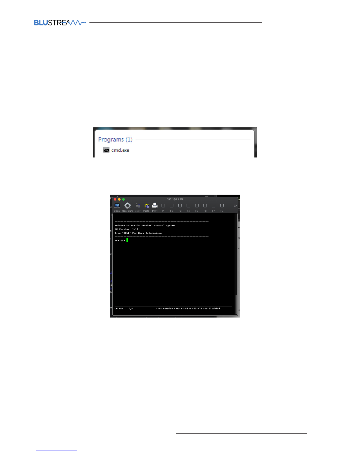
ACM200 USER MANUAL
53
contact [email protected] / [email protected]
Telnet error
If the error message: ‘telnet is not recognized as an internal or external command, operable program or batch file’,
activate Telnet on your computer.
Unable to see the LAN ports of the ACM200
If unable to communicate (ping) the ports of the ACM200, connect directly to the network switch and not via a
DHCP modem router to test.
Able to ping the device but not login via Telnet connection
If unable to communicate (ping) the ports of the ACM200, connect directly to the network switch and not via a
DHCP modem router to test.
Troubleshooting the ACM200
Try using the below instructions to test the ACM200 should diiculties be encountered when using a computer to
control the ACM200.
1. Connect the computer directly to the ACM200 Control Port with a CAT cable
2. The computer must be in the same range as the LAN connection 1 on the ACM200 device (CONTROL net
work) as this will simulate the control from a third party control system (i.e. Control4, RTI, ELAN etc). Please
see instructions at the rear of this manual for ‘Changing your computer IP details’.
3. Open cmd.exe program (Command prompt). Use the search tool of the computer if unsure where this is
located.
4. Enter the following command line ‘Telnet 192.168.0.225’
The following window will be displayed to confirm being logged into the ACM200 successfully:
Page 54
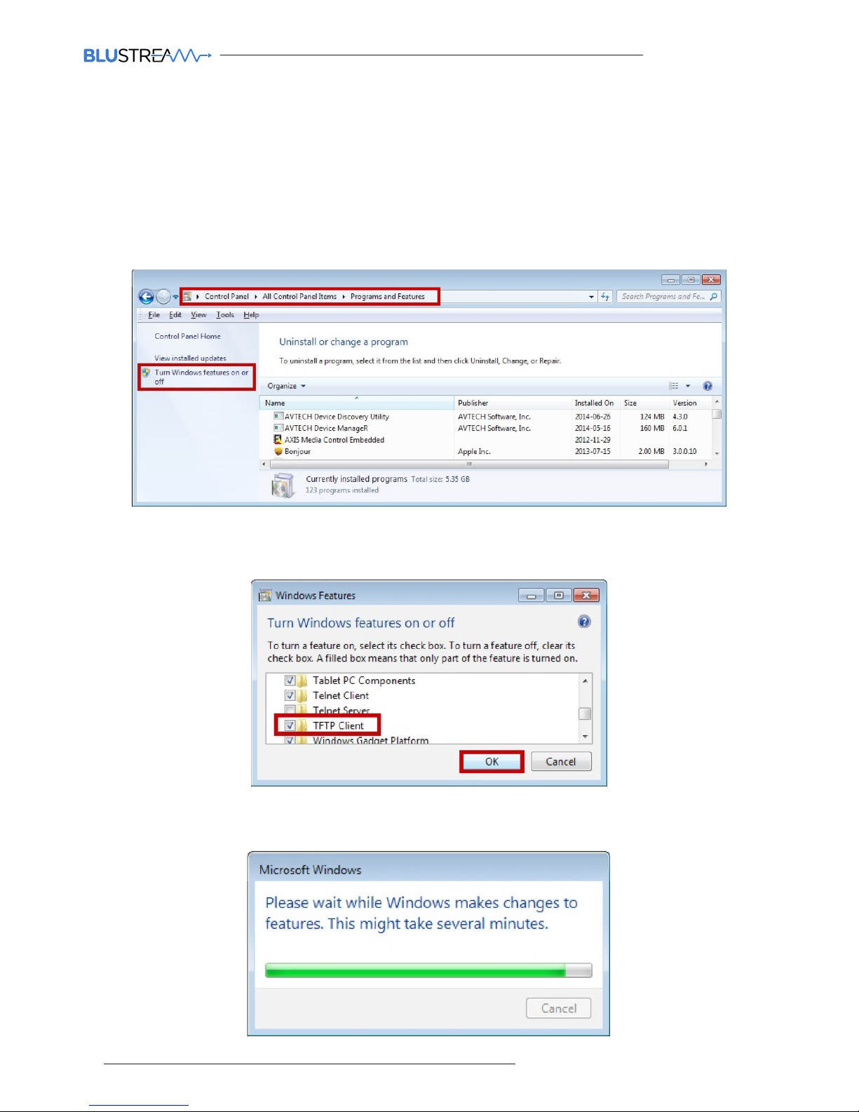
ACM200 USER MANUAL
54
www.blustream.co.uk / www.blustream.com.au
Adjusting Your Computer Settings - Enabling TFTP & Telnet
Prior to using the Blustream ACM200 Firmware update PC program you must activate both TFTP and Telnet features on the computer. This is achieved using the following steps below:
1. In Windows, navigate to: Start -> Control Panel -> Programs and Features
2. In the Programs and Features screen, select Turn Windows features on or o in the navigation bar on the
le.
3. Once the Windows Features window populates, scroll down and make sure “TFTP client” and “Telnet
Client” are both selected.
4. Once the progress bar fills and the pop up disappears, the TFTP client is enabled.
Page 55

ACM200 USER MANUAL
55
contact [email protected] / [email protected]
Setting a fixed IP address in Windows 7, 8 or 10
In order to communicate with the ACM200 your computer must first be in the same IP range as the ACM200 Control
or Video LAN ports. By default the ports have the following IP address:
Control LAN port 192.168.1.253
Video LAN port 169.254.1.253
The following instructions allow a manual alteration of the IP address of the computer allowing a communication
with Blustream Multicast devices.
1. In Windows, type 'network and sharing' into the search box
2. When the Network and Sharing screen opens, click on 'Change adapter settings'.
Page 56
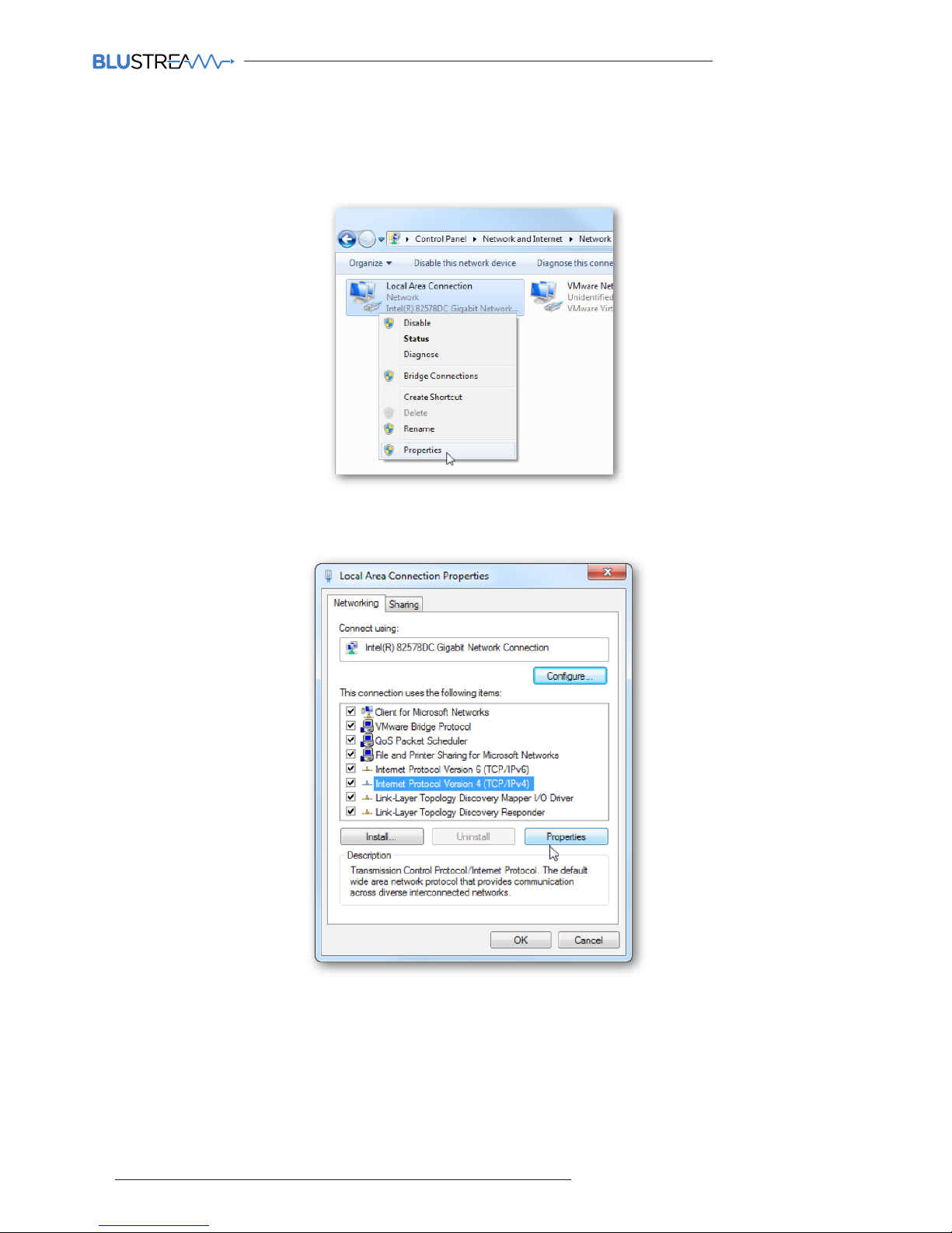
ACM200 USER MANUAL
56
www.blustream.co.uk / www.blustream.com.au
3. Right click on the Ethernet adaptor and click Properties
4. In the Local Area Connection Properties window highlight Internet Protocol Version 4 (TCP/IPv4) then click
the Properties button.
Page 57
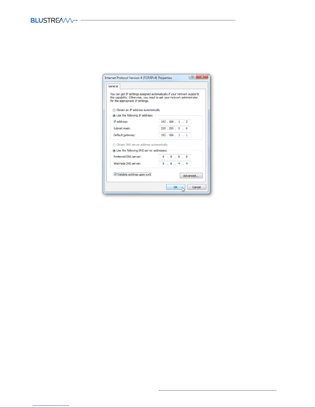
ACM200 USER MANUAL
57
contact [email protected] / [email protected]
5. Use the following IP address and enter in the correct IP, Subnet Mask, and Default gateway that corre
sponds with the network setup.
6. Press OK and close out of all network screens.The computers IP address has now been fixed.
Page 58

ACM200 USER MANUAL
58
www.blustream.co.uk / www.blustream.com.au
Notes...
Page 59

www.blustream.co.uk
www.blustream.com.au
 Loading...