

Page 1
1
6
0
0
0
9
1
5
0
3
E
N
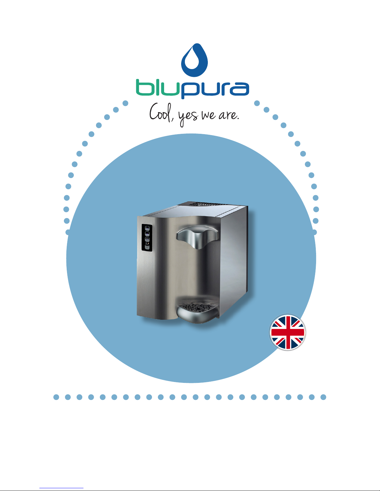
mod. Touch, I.T., Light
WAV E
U
s
e
&
M
a
i
n
t
e
n
a
n
c
e
M
a
n
u
a
l
Page 2

Page 3

3
Index
• BEFORE INSTALLING THE WATER COOLER 4
• RECOMMENDATIONS FOR SAFEGUARDING THE ENVIRONMENT 5
• DECLARATION OF CONFORMITY 6
• ASSOCIATIONS 7
• INTERNATIONAL AWARDS 7
• PRECAUTIONS AND GENERAL RECOMMENDATIONS 8
• DESCRIPTION OF THE UNIT 9
• DESCRIPTION OF THE TOUCH VOL AND I.T. VOL KEYPAD 13
• FUNCTIONS OF THE VOLUMETRIC KEYPAD 14
• FUNCTIONS OF THE TOUCH KEYPAD 16
• FUNCTIONS OF THE LIGHT I.T. AND LIGHT KEYPADS 17
• TECHNICAL FEATURES 18
• INSTALLATION 21
• INSTALLATION OF THE CO2 CYLINDER (FIZZ MODEL) 25
• HANDLING THE GAS CYLINDERS 26
• FILTRATION (OPTIONAL) 27
• SANITIZATION – NOTES 29
• ORDINARY MAINTENANCE 30
• SERVICE HISTORY 31
• WARRANTY CONDITIONS 32
Page 4

4
Before installing the water cooler
Congratulations for choosing a BLUPURA product.
We have designed and manufactured this product with great care to ensure that
it will dispense water of the highest quality.
In order to get the most out of your water cooler, please read the instructions in
this manual and retain the manual for future reference.
Page 5
5
Recommendations for safeguarding the environment
Packaging materials
The packaging materials are 100% recyclable.
Please follow the local guidelines on waste
disposal. For safety reasons keep the packaging
material out of the reach and sight of children.
Scrappage
The water cooler is made using recyclable material.
This unit is marked in compliance with European Directive 2002/96/EC
on Waste Electrical and Electronic Equipment (WEEE). By ensuring that
the product is scrapped correctly, you are helping to prevent potential
negative consequences for the environment and for health. The symbol
on the unit indicates that the product should not be treated as domestic waste
but should be taken to a dedicated recycling centre for electrical and electronic
equipment. Immediately prior to scrapping, cut off the power cable.
For more information on the treatment, recovery and recycling of this product,
please contact the appropriate local office, the waste disposal service or the
reseller from which the product was purchased.
Information on the natural, eco-friendly refrigerant gas used in
this cooler
This product contains no CFCs or HFCs, which contribute to global warming.
Indeed, it is the first water cooler on the market to use natural refrigerant.
The refrigerating system is filled with HC R290 – Propane: a natural gas that does
not contribute to global warming and that, thanks to its specific characteristics,
allows for substantial energy savings to be made.
Page 6
6
Declaration of conformity
Materials compliant for contact with drinking water
This unit is intended for the dispensing of drinking water, and so the materials
that enter into direct contact with water meet the criteria for food-grade
components pursuant to the current legislation. In addition, the unit is
manufactured in compliance with Italian Ministerial Decrees 174 of 06/04/2004
and 25 of 07/02/2012.
Electrical safety
This water cooler is designed, manufactured and marketed in compliance with:
• the safety objectives of the Low Voltage Directive 2006/95/EC;
• the protection requirements of the Electromagnetic Compatibility Directive
2004/108/EC.
The electrical safety of the product is ensured only when it is properly connected
to an efficient, legally compliant grounding circuit.
D.M. 174
1
0
0
%
M
A
D
E
I
N
I
T
A
L
Y
C
E
R
T
I
F
I
C
A
T
E
I
T
P
I
UNI EN ISO 9001:2015
UNI EN ISO 14001:2015
Page 7
7
Associations
International Awards
2015 - BEST PROMOTION OF HEALTH AND HYDRATION
EUROPEAN AQUA AWARDS 2015, ROME
2015 - BEST ENVIRONMENTAL PRACTICE/GREEN INITIATIVE
EUROPEAN AQUA AWARDS 2015, ROME
2014 - BEST PROMOTION OF HEALTH AND HYDRATION
EUROPEAN AQUA AWARDS 2014, BUDAPEST
2013 - BEST PRODUCT INNOVATION
EUROPEAN AQUA AWARDS 2013, BERLIN
2012 - BEST ENVIRONMENTALLY FRIENDLY PRACTICE
EUROPEAN AQUA AWARDS 2012, ISTANBUL
2011 - BEST PRODUCT DESIGN/INNOVATION
EUROPEAN AQUA AWARDS 2011, ODESSA
2010 - BEST ENVIRONMENTALLY FRIENDLY PRACTICE
EUROPEAN AQUA AWARD 2010, PRAGUE
Page 8
8
Precautions and general recommendations
Always connect the water cooler to a water main that
supplies drinking water only.
Before each installation, the unit must be sanitized by an
authorized technician.
After installation, ensure that the unit is not resting on the
power cable.
Check that the unit is level and that it is resting on a floor
with sufficient load-bearing capacity, in an environment that
is suitable for its dimensions and its use.
Before any maintenance or cleaning operation is carried out, remove the plug from the
socket or disconnect the power supply.
Ensure that the product is not sited close to sources of heat.
To guarantee adequate ventilation, leave at least 10 cm of space around the unit.
Install the product in a clean, dry, well-ventilated environment. The water cooler is designed
to function in environments with a temperature range of between 5°C and 32°C - Climate
Class N.
Take care not to damage the cooling fluid circuit: it is filled with natural gas HC R290, which
is a highly flammable gas. It is essential to ensure that the tubes of the refrigerant circuit are
not damaged.
The unit is not intended for use by children.
If the power cable is damaged, it must be replaced by the manufacturer, by its technical
support service or by a qualified technician. Do not use extension cables or multi-plugs.
Ensure that it is possible to disconnect the power supply either by removing the plug or via
a two-pole circuit-breaker placed upstream of the plug.
Check that the voltage shown on the serial number plate corresponds to the voltage being
supplied at the installation site.
The unit must not be cleaned with a water jet. Do not position other electrical equipment in
the immediate vicinity of the water cooler.
Turn off the main water inlet tap if the unit is not to be used for a long period.
Keep the areas surrounding the unit dry to avoid the risk of people slipping.
This appliance is not intended for use by persons (including children) with reduced
physical, sensory or mental capabilities, or lack of experience and knowledge, unless
they have been given supervision or instruction concerning use of the appliance by a
person responsible for their safety. Children should be supervised to ensure that they
do not play with the appliance .
The Appliance shall be protected by a ground-fault circuit interrupter.
Page 9
9
Description of the unit
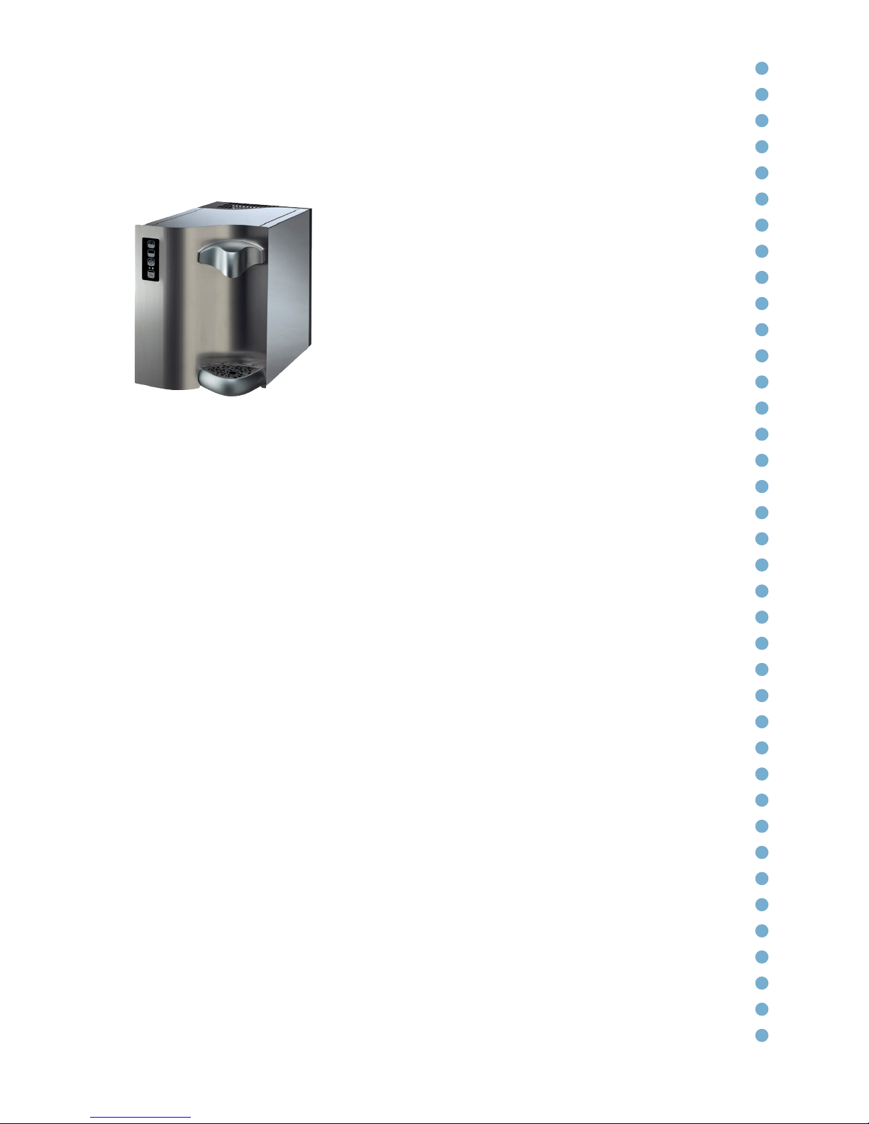
A new product designed with the highest level of quality, design and
technology. The main features of the unit are as follows:
• A modern design using natural materials
• Highly insulated ice-bank, for greater energy
saving
• Cooling serpentine coil, without water
stagnation, made with the best AISI 316 stainless
steel for drinkable water.
• 3 supply options (FIZZ model): cold water +
room-temperature water + cold sparkling water
• Easily programmable water dosage system
with volumetric control (VOL model)
• Glass touch-screen controls, easy to use and hygienic
• Self-diagnosing system and alarm in case of lack of mains water, lack of CO2
in cylinder and water leakage
• ENERGY SAVING control: when needed puts the machine into stand-by
mode with an energy saving of 75% of full operational energy. Saving energy but,
thanks to the low temperature, stops the proliferation of bacteria (TOUCH and I.T.
VOL models)
• Body and internal parts made entirely from stainless steel
• WAVE received third prize for “Best Product Design/Innovation” for 2010
from the European EBWA association
Page 10
10
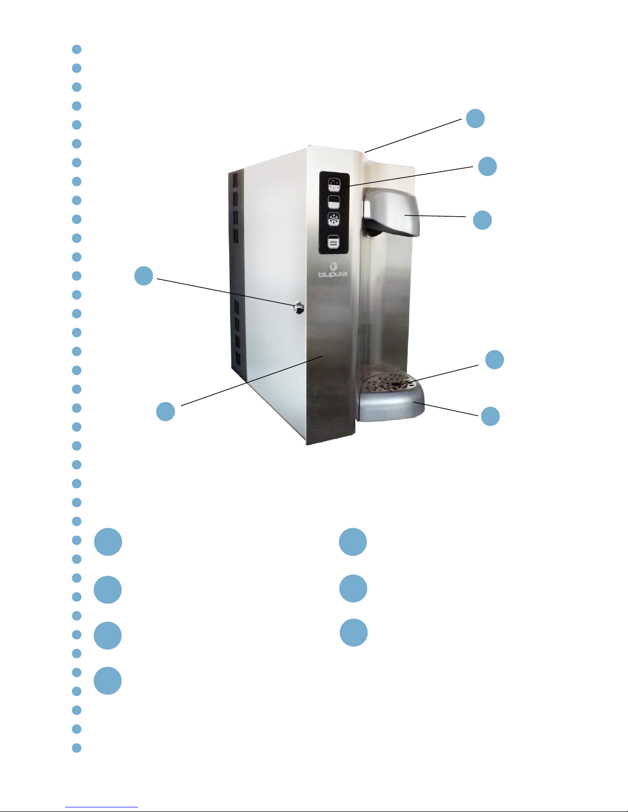
External Front View
1
3
4
5
6
7
2
5
6
7
2
3
4
1
Safety lock
Removable Top Cover
Touch control keypad
Draft protection
Front Door
Drip Tray Grid
Drip
Page 11
11
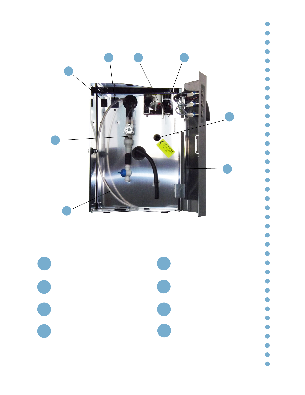
Internal Frontal View
1
32 4
5
6
7
8
5
6
7
8
2
3
4
1
General switch
Adjustable thermostat
Exit water solenoid valve
Removable exit water pipe
Ice bank inlet pipe joint Ø5/16”
(8 mm)
Inlet safety valve with check
valve and mechanical filter
Ø5/16” (8 mm)
Ice bank drainage pipe
CO2 inlet pipe Ø5/16” (8 mm)
Page 12
12
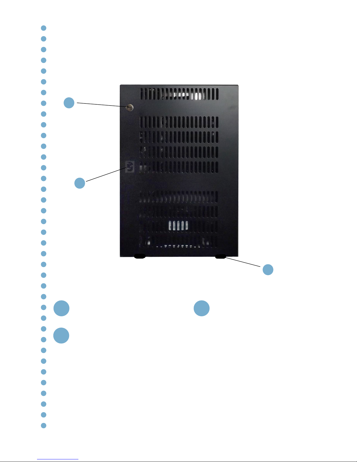
Rear View
1
2
3
3
2
1
ENERGY SAVING button (only I.T.
VOL model)
IEC inlet power cord
Support feet
Page 13
13
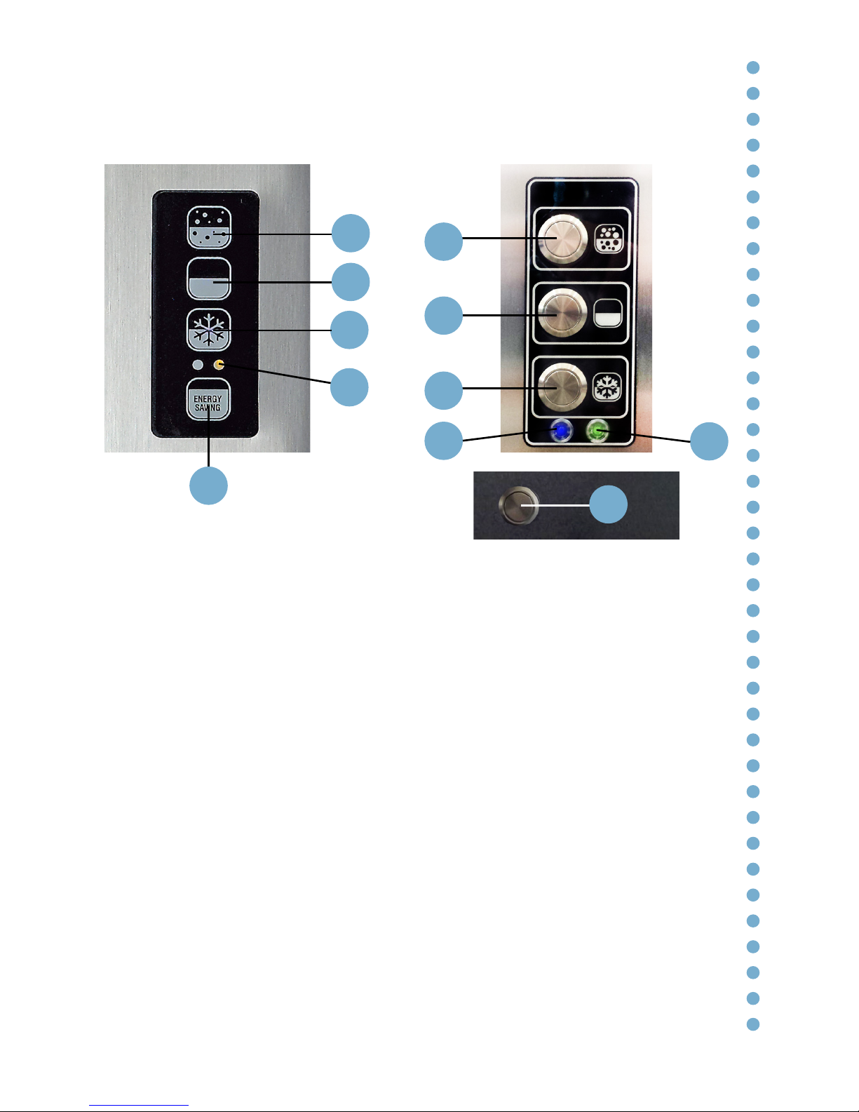
Description of the TOUCH VOL and I.T. VOL keypad
P. 1 Cold sparkling water dispensing button (only FIZZ model)
P. 2 Room-temperature water dispensing button
P. 3 Cold still water dispensing button
P. 4 ENERGY SAVING button (on the back in I.T. VOL model)
L.1 Led alarm indicators:
RED led on the LEFT - Little or no water at the inlet
YELLOW led on the RIGHT - Little or no CO2 remaining* (FIZZ model)
L.2 BLUE led (STAND-BY):
Quick flashing - Little or no water at the inlet
Slow flashing - Little or no CO2 remaining* (FIZZ model)
L.3 GREEN led:
Static - ENERGY SAVING mode active
Flashing - Dose programming mode active
*optional for WAVE FIZZ 30 models
Fig. 13.1 - TOUCH keypad
Fig. 13.2 - I.T. VOL keypad
Fig. 13.3 - Rear view
P. 1
P. 2
P. 3
P. 1
P. 2
P. 3
P. 4
P. 4
L.1
L.2
L.3
Page 14
14
Functions of the volumetric keypad
The TOUCH VOL watercooler is provided with a TOUCH SCREEN PANEL (Fig.
13.1) with 4 back-lit commands. 3 commands control the supply of water, 1
controls the stand-by (ENERGY SAVING function, P.4).
When the appliance is turned on an automatic visual test of the ALARM LED (L.1)
lights up in sequence followed by the supply commands (P.1 – P.3).
The water cooler (both mod. TOUCH VOL and I.T. VOL) is equipped with
a VOLUMETRIC dispensing system. The dispensing quantities are easily
PROGRAMMABLE during installation and it’s possible to set two quantities for
each button. On turning on the unit, the default settings are as follows: a short
push of the button dispense 200 cc (a cupful) of water, whereas a long push
dispense 1000 cc (1 litre).
BUTTON FUNCTIONS:
- SPARKLING WATER DISPENSER button (P.1)
- ROOM-TEMPERATURE WATER DISPENSER button (P.2)
- COLD WATER DISPENSER button (P.3)
While the water is being dispensed, the LED turns itself off. You can stop the
dispensing process at any time by pressing the button again.
SETTING THE QUANTITIES:
Thanks to the Volumetric dispensing functionality, you can customize the pre-set
quantities dispensed by each of the 3 buttons. Normally, a SHORT push of the
buttons used for the dispensing of small quantities, with a LONG push being
used for the dispensing of larger quantities. The default settings are 200 cc for a
short push and 1000 cc (1 litre) for a long push.
To enter the programming mode, press and hold (for > 4 seconds) the following
combination of buttons: P.4 + P.2 (Energy Saving button + “Room temperature”
button). When you enter the programming phase, you will hear three consecutive
beeps.
In this phase, the LED of button P.4 (Energy Saving) and the LEDs of the
dispensing buttons (TOUCH VOL mod.) or the GREEN led L.3 (I.T. VOL mod.) start
to flash.
To set the maximum dispensing limit for a specific button, press the button in
question to start the dispensing process: : a SHORT push for the dispensing of
* Functions of the“Touch Control” keypad. All of the
operations must be carried out exclusively by qualified
technical personnel. To view the video tutorial, scan the
QR code.
Page 15

15
small quantities or a LONG push for larger quantities. Press it again once you
have reached the desired quantity. When the limit for the button has been set, the
corresponding LED (TOUCH VOL mod.) or the BLUE led L.2 (I.T. VOL mod.) stays
on. Repeat the process for the remaining buttons.
To exit from the programming mode, press and hold (for > 4 seconds) the
following combination of buttons: P.4 + P.2 (Energy Saving button + “Room
temperature” button), save the data and set the new limits.
The maximum settable quantity for each button is around 3,0 litres, which
equates to a 65-second dispensing session.
FUNCTIONALITY WITH ALARMS ACTIVATED:
“NO WATER” ALARM: This alarm is triggered when the pump sends the NO
WATER signal. In this case, the associated RED LED turns itself on (TOUCH VOL
mod.) or the BLUE led L.2 starts to flash quickly (I.T. VOL mod.) and the sparkling
water dispensers do not work. The other dispensers continue to work as normal.
To reset the alarm, turn the unit off and back on again.
“NO GAS” ALARM: This alarm is triggered when the CO2 pressure switch sends
the NO GAS signal. In this case, the associated YELLOW LED turns itself on
(TOUCH VOL mod.) or the BLUE led L.2 starts to flash slowly (I.T. VOL mod.) and
all of the dispensers continue to work as normal.
ATTENTION: on model WAVE FIZZ 30 this alarm is optional.
ENERGY SAVING (STAND BY): The function is activated pressing button P4
briefly, for less than 4 seconds (on the back of the machine in I.T. VOL model).
The ENERGY SAVING (STAND BY) mode slows down the activation time of the
compressor; the compressor functions for 30 minutes every 8 hours.
When the unit is on STAND BY, the P4 light (TOUCH VOL mod.) or the GREEN
let L.3 (I.T. VOL mod.) are on, whereas all of the other lights are off. When it is not
on STAND BY, the P4 light is off (TOUCH VOL. mod), and all of the other lights
or the BLUE led L.2 (I.T. VOL mod.) are on. Once the STAND BY function has
been activated, it can be deactivated using button P4 or any other button for the
dispensing of water.
KEY LOCK (only model TOUCH VOL): Pressing and holding button P4 (ENERGY
SAVING/ STAND BY) for more than 4 seconds will activate/deactivate the
keylock (e.g. for use when you want to clean the keypad). When locked, all of the
dispensing buttons are deactivated and the lights associated with the dispensing
buttons flash alternately. When the command is activated, the unit emits a beep.
Page 16

16
Functions of the TOUCH keypad
The TOUCH watercooler is provided with a TOUCH SCREEN PANEL (Fig. 13.1)
with 4 back-lit commands. 3 commands control the supply of water, 1 controls the
stand-by (ENERGY SAVING function). (P.4)
When the appliance is turned on an automatic visual test of the ALARM LED (L.1)
lights up in sequence followed by the supply commands (P.1 – P.3)
BUTTON FUNCTIONS:
- SPARKLING WATER DISPENSER button (P.1)
- ROOM-TEMPERATURE WATER DISPENSER button (P.2)
- COLD WATER DISPENSER button (P.3)
The water is dispensed while pressure is being applied to the button. During the
supplying there is a Beep sound and led are switch off.
- STAND-BY/KEYPAD LOCK button (P.4)
A short push of the button activates the stand-by function. In this case, the LEDs
of all the dispensing buttons and the POWER-ON LED are turned off, while
the stand-by button GREEN LED is turned on. If turned on, after 5 minutes the
compressor shuts down and it’s switched on every 8 hours for half an hour. To exit
the stand-by mode, press any of the dispensing buttons or the stand-by button.
The stand-by is activated only when dispensing are interrupted.
A long push (4 seconds) on the stand-by button blocks the keypad. The LEDs of
the dispensing buttons light up alternately. In this case, all dispensing buttons are
disabled.
To activate the keypad again, push for 4 second the stand-by button.
Page 17
17
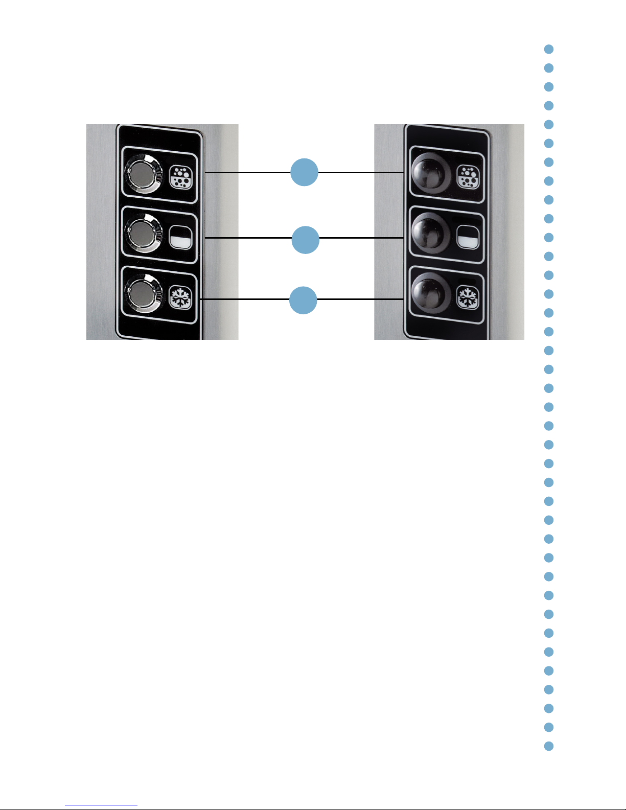
The watercooler (LIGHT I.T. and LIGHT models) is provided with a mechanical
button keypad.
BUTTON FUNCTIONS:
- SPARKLING WATER DISPENSER button (P.1)
- ROOM-TEMPERATURE WATER DISPENSER button (P.2)
- COLD WATER DISPENSER button (P.3)
The water is dispensed while pressure is being applied to the button.
Functions of the LIGHT I.T. and LIGHT keypads
P. 1
P. 2
P. 3
Fig. 17.1 - LIGHT I.T. keypad
Fig. 17.2 - LIGHT keypad
Page 18
18
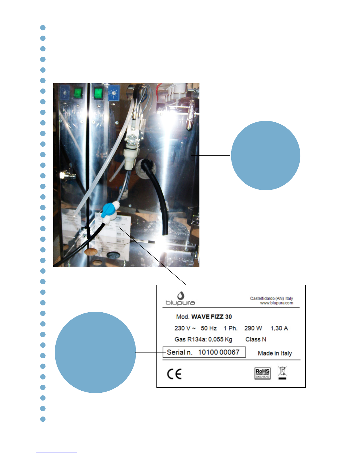
Technical Features – Technical Data Plate
10 Year of manufacture
10 Month of manufacture
00067 Serial number
[mod. Wave]
Page 19
19
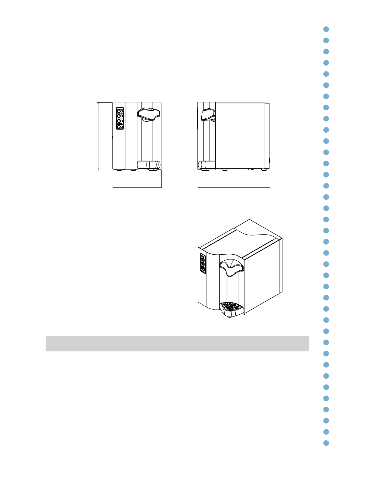
Technical Features - dimensions (mm)
[mod. Wave]
Dimensions WAVE 30 WAVE 60 WAVE 80
LxDxH (mm)
272x453x467
330x489x467 330x599x467
H
L W
Page 20
20
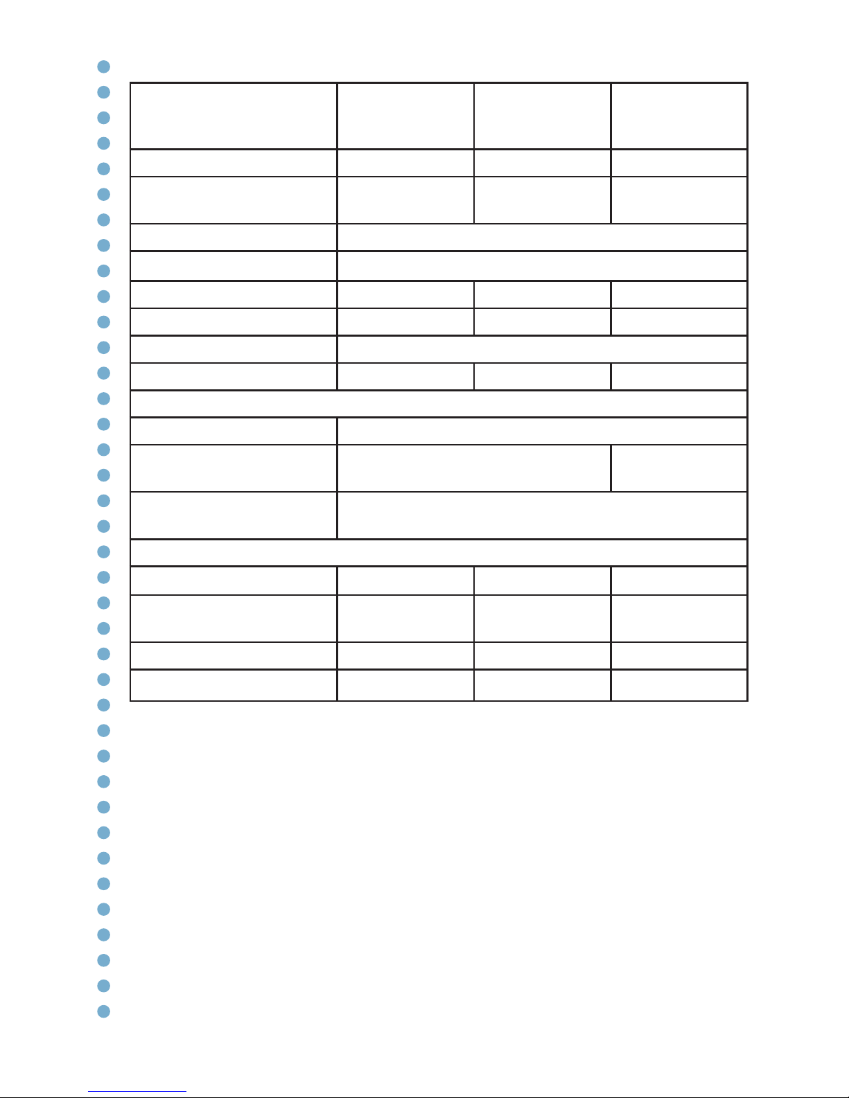
Technical data
sheet
WAVE 30 WAVE 60 WAVE 80
Cooling capacity 30 lt/h 60 lt/h 80 lt/h
Max Continuous cooling
capacity
6 lt 18 lt 45 lt
Water temperature 5°-10°C *
Cooling technology
Ice bank — single stainless steel coil
Ice bank capacity 4 lt 7 lt 14 lt
Ice bank 1,5 kg 3,5 kg 5,5 kg
Supply Single phase 230V-50Hz
Power 180 W 350 W 450 W
Condensation Forced ventilation (fan)
Refrigerant gas
HFC R134a
Natural gas HC
R290
Working room
temperature
Min 5°C - Max 32°C
Dimensions LxDxH (mm)
272x453x467
330x489x467 330x599x467
Packing dimensions
(mm)
340x490x490
400x560x490 400x670x490
Net weight (kg) 20 35 40
Gross weight (kg)
22 38 43
* rated at a room temp. of 25°C and inlet water temp. of 20°C
Page 21
21
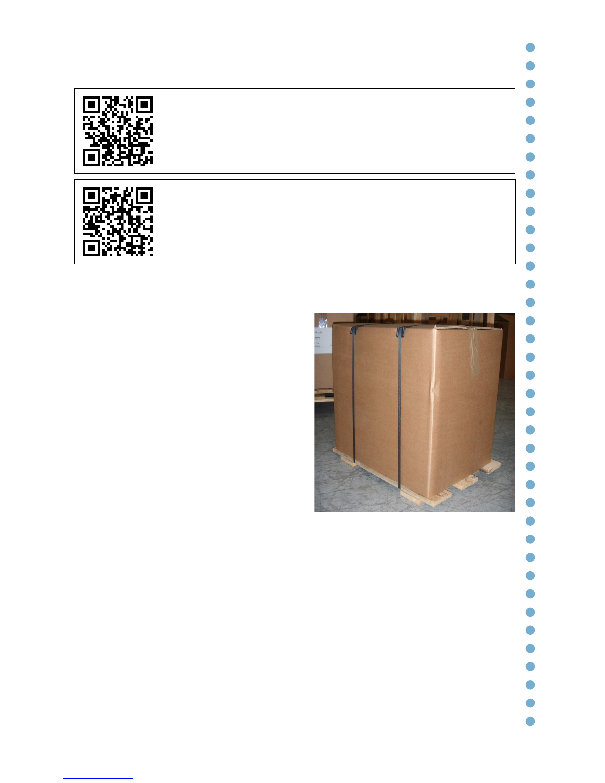
* Installation Touch model. All of the operations
must be carried out exclusively by qualified technical
personnel. To view the video tutorial, scan the QR code.
* Installation Light model. All of the operations must be
carried out exclusively by qualified technical personnel.
To view the video tutorial, scan the QR code.
Unpacking
Remove the two plastic tape.
Lift the internal cardboard box up
and out of the cage. Carefully check
that the watercooler has not been
damaged during transport. Any signs of
damage must be reported to the Agent
immediately.
If the watercooler has been transported in
a horizontal or inclined position, a wait of
8 hours is needed before turning it on so
that the refrigeration circuit can function
perfectly.
Ensure that a qualified technician
connects it to the electric supply following
the manufacturer’s instructions and
according to the local safety regulations
The end user is not permitted to access
the internal service parts of the unit. Only
technical personnel should carry out
operations of this nature.
Installation
Page 22
22
Fig. 22.2
Fig. 22.1
Siting the unit
Wear safety gloves when handling the
unit. Take care when touching the metal
parts, which could be sharp.
Site the unit away from sources of heat.
Leave at least 10 cm around the unit to
allow for aeration.
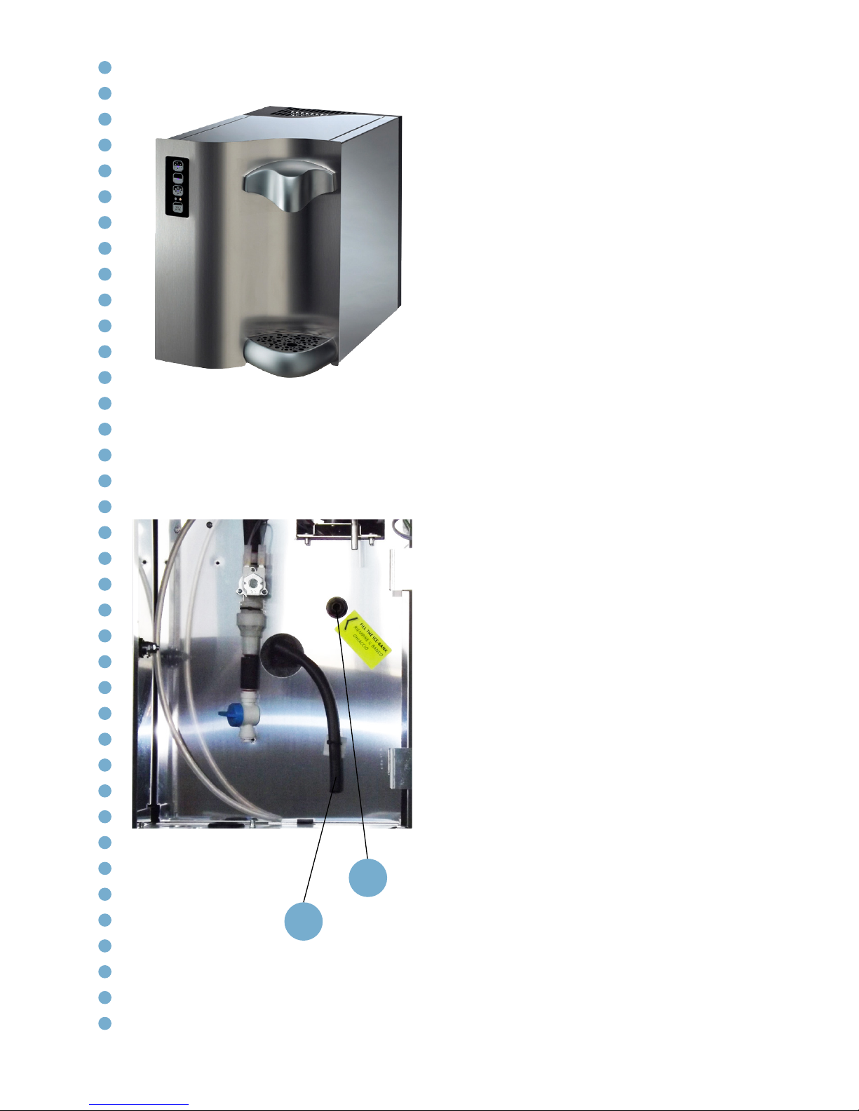
Filling the Ice Bank
Open the rear panel using the supplied
key.
Fill the ice bank using the specific inlet
pipe joint Ø5/16” (8 mm) (1).
The ice bank is completely full only when
water starts to come out of waste water
tube (2).
Once you have filled the ice bank, avoid
moving the unit.
If you have to move the unit, remember
to empty the ice bank first.
1
2
Page 23
23
Fig. 23.1
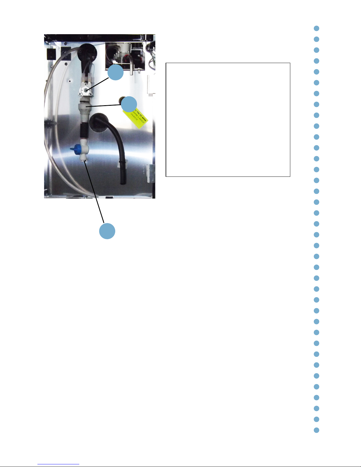
Connection to the mains
water supply
Check that the mains pressure
is between 1 bar and 3,5 bar. To
enhance the quality of the sparkling
water dispensed, an incoming
flow rate in excess of 3.5 l/min is
recommended.
Use a food grade pipe (external
diameter 5/16” = 8 mm) to connect
the water supply entry (1) to the mains
water supply, preferably with a wall
tap.
The watercooler comes with a nonreturn valve (2) and a security valve (3).
It’s not included a water pressure
reducer, that must be assembled
before the WAVE.
Once the pipes are attached, turn on
the tap. Ensure there are no leaks.
Caution!
To connect the water cooler to the
mains water supply, you will need to
use a new set of connectors (joints,
gaskets and pipes).
Do not use a set of connectors that has
already been used elsewhere.
The water pressure entering the unit
must be between a minimum of 1,0
bar (0,10 MPa) and a maximum of 3,5
bar (0,35 MPa)
1
2
3
Page 24
24
Fig. 24.1
Fig. 24.2
Fig. 24.3
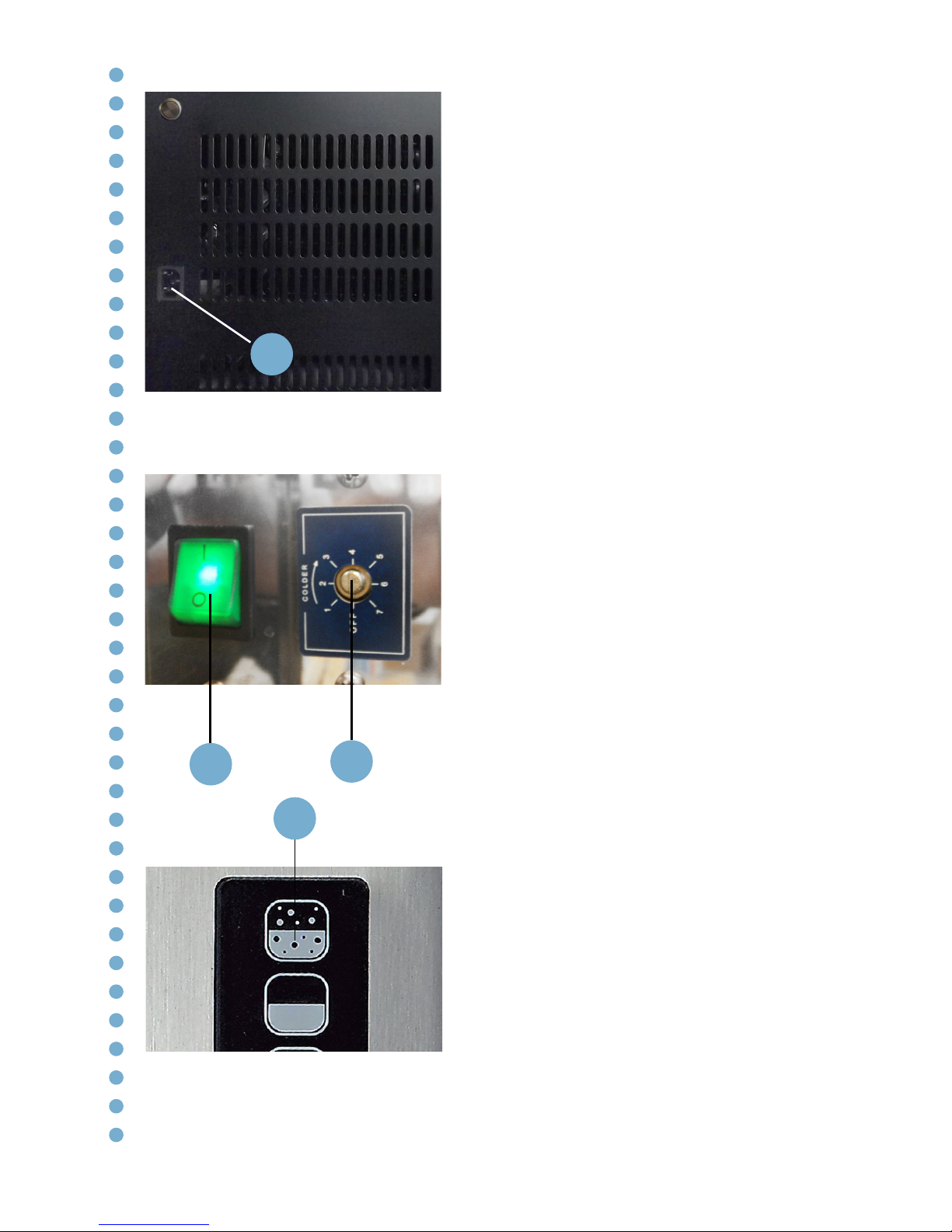
Electrical connection
The connections must comply with local
regulations. The grounding of the unit is
a legal requirement.
Connect the power cord to the IEC inlet
(1) and to a socket.
Turn the unit on by selecting the “I”
position on the main on/off rocker switch
(2). The compressor and fan are now
activated.
On the FIZZ models, press the “Sparkling
Water” button on the right (4) in order
to release any air in the circuit and to
allow the pump to activate and fill the
carbonator with water.
After around 1-2 minutes, the sparkling
water pump stops.
Thermostat
The thermostat (3) is set in the maximum
position to control the ice bank.
If you want to avoid the formation of ice
in the bank, turn the thermostat screw at
least 1/4” anti-clockwise.
1
3
4
2
Page 25
25
Fig. 25.2
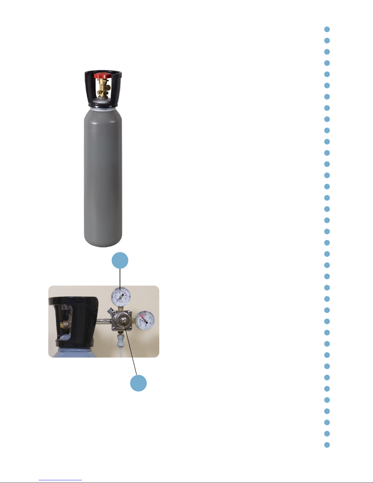
Once the unit is connected to the mains
water and electricity, and the ice-bank
tank has been filled, you can install the
E290 food-grade carbon dioxide (CO2)
cylinder.
The machine is NOT equipped with the
CO2 pressure reductor, which must be
ordered separately. Also, the CO2 cylinder
is not provided.
It’s not possible to install CO2 cylinders
inside the unit.
To increase or decrease the level of
carbonation of the water, you need to
adjust the screw (1). Turning it clockwise
increases the level of carbonation. We
recommend that you do not exceed 4
bars of pressure (2).
To reduce the carbonation level, turn
the screw anti-clockwise. The level will
decrease as soon as sparkling water is
dispensed.
To achieve a good level of carbonation,
you need to wait until the water is
sufficiently cold – i.e. at least one hour
after installation.
Installation of the CO2 cylinder (FIZZ model)
1
2
Fig. 25.1
Page 26
26
* Replacement of the CO2 cylinder. All of the operations
must be carried out exclusively by qualified technical
personnel. To view the video tutorial, scan the QR code.
* Suggestions for optimal carbonation. All of the
operations must be carried out exclusively by qualified
technical personnel. To view the video tutorial, scan the
QR code.
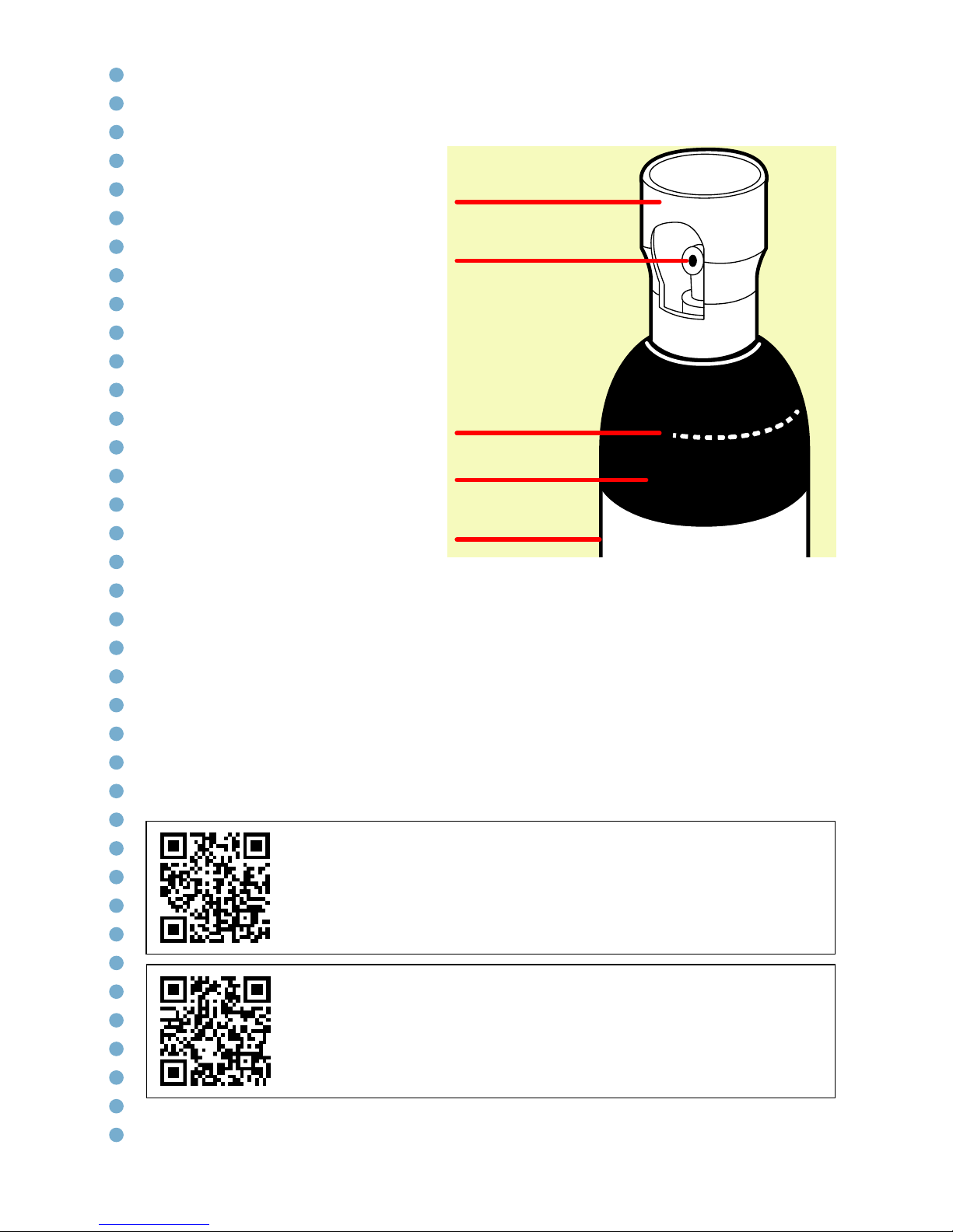
Handling the gas cylinders
All of the cylinders must be fitted
with a valve protector cap, which
must be on tight at all times when
the cylinder is not in use.
The cylinders must be handled
with care. It is essential to avoid:
clashes with other cylinders or
surfaces; dropping the cylinders;
or subjecting them to mechanical
stress. All of the above may
compromise their integrity and
resistance.
The cylinders must not be lifted
by the cap, or dragged, rolled or
slid along the floor. Even if only
being moved for short distances,
an appropriate hand cart or other
suitable means of transport should
be used.
Do not use magnetic lifters or slings with ropes or chains to lift the cylinders.
If the cylinders are to be lifted with cranes, hoists or fork-lift trucks, ensure that
appropriate cages, metal baskets or pallets are used.
The cylinders must not be moved or handled with greasy hands or gloves. This is
particularly important in relation to cylinders containing oxidising gases.
Cap
Valve connection
Shoulder
Markings
Body
Page 27
27
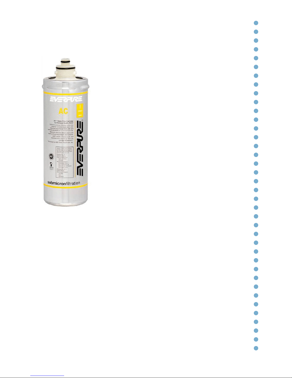
Filtration (optional)
AC Filter
On request, the unit can be fitted with an Everpure
AC filter.
MAIN FEATURES
This filter removes the odour and flavour of chlorine
and other contaminants that can alter the taste
of the water. The Precoat microfiltration system
removes impurities and particles with dimensions of
0.5 microns and above.
It also reduces the levels of any contaminants such
as asbestos fibres and micro-organisms such as
Cryptosporidium and Giardia.
It protects gaskets, pumps, tubes and valves against
blockages, corrosion and abrasions.
Approved by the Italian Ministry of Health and
the Water Regulations Advisory Scheme (UK), it is
certified compliant with the NSF/ANSI standards 42
and 53.
The cartridge should be changed every 6 MONTHS.
Its maximum capacity is 2800 litres.
Page 28
28
Filtration (optional)
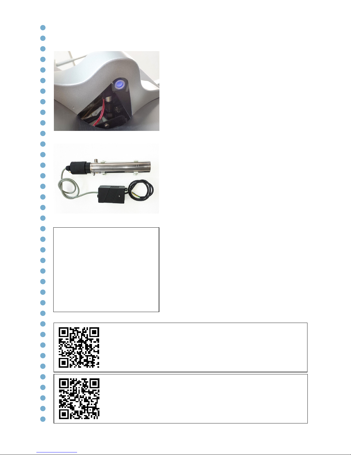
Sterilizing UV filter
Alongside the Everpure AC filter, it is also
possible to install an Ultraviolet sterilizing
filter (λ=254 nm) BLUPURA UVC OUT
QUARTZ 4W Wave/Ecochic 150068 (Max
lamp rating 1,2W 600V) on the water exit
point to avoid backflow contamination and
a sterilizing filter BLUPURA UVC IN QUARTZ
12W 150043 on the water entry point.
The UV-C light emitted by the special 12W
mercury vapour lamp is lethal for all microorganisms (bacteria, viruses, mould, algae,
etc.); for this reason, water treated with the
UV-C sterilizer will be microbiologically pure.
TECHNICAL PROFILE
Material AISI 304
Electricity supply 220V-50Hz
Power 12Wh
Maximum water flow 5 liters/min
Minimum pressure 0.5 bar
Maximum pressure 9 bar
Radiation 30,000 µWs/cm2
Green LED ON = bulb is on
Maximum duration of the bulb 8.000 hours
(11 months). The UV sterilizer is made
entirely in Italy and complies with Italian and
European quality and safety guidelines.
Caution!
The light emitted by the ultraviolet lamp may cause serious
burns to the eyes and skin.
Do not remove it from its
stainless-steel container – only a
qualified technician should do
so.
* Replacement of the external lamp. All of the
operations must be carried out exclusively by qualified
technical personnel. To view the video tutorial, scan the
QR code.
* Replacement of the internal lamp. All of the
operations must be carried out exclusively by qualified
technical personnel. To view the video tutorial, scan the
QR code.
Page 29
29
Sanitization – Notes
The unit should be sanitized at first
installation, or when the hydraulic
components are being replaced, or when
the filter is being changed, or in any case
at least once a year.
This operation must be carried out by
the BLUPURA Reseller or by qualified
technical personnel who have
completed specific training courses on
hygiene and sanitization.
To sanitize the unit, we recommend the
use of hydrogen peroxide (oxygenated
water), 5% diluted in drinking water.
For more details on this operation,
consult the SANITIZATION section in the
BLUPURA technical manual.
* Filter replacement and sanitization. All of the
operations must be carried out exclusively by qualified
technical personnel. To view the video tutorial, scan the
QR code.
Page 30

30
Ordinary maintenance
External cleaning of the unit
To clean the unit, use the BLUSTEEL ULTRAMICROFIBRA cloth (code 190094),
which is specifically designed for our products. Alternatively, you can use a soft
cloth and a dedicated product for the cleaning of stainless steel. To remove
limescale, use a slightly acidic product (e.g. citric acid) that has been heavily
diluted – excessive acidity risks ruining the surface of the steel.
DO NOT USE alcohol- or solvent-based products.
Cleaning the drip tray
When it is necessary to clean the drip tray, use a diluted limescale cleaner (citric
acid or similar).
The drip tray can also be washed in the dishwasher.
Cleaning the dispensing nozzles
On a daily basis, spray our SANIFICATION SPRAY (code 190010) onto the
nozzles. Alternatively, you can use a diluted hydrogen peroxide solution (e.g.
Cooler Clean).
Cleaning the Touch Control keypad
Before cleaning the keypad, it is essential to lock it so as to avoid the command
being given accidentally to dispense water.
To block the keypad, press and hold (for > 4 seconds) the Energy Saving button
at the lower right. All of the LEDs will start to flash.
To unlock the keypad, press and hold the button (for >4 seconds). The LEDs will
remain constantly on, without flashing.
Clean with a soft cloth and alcohol-free glass-cleaning products.
DO NOT USE a jet of water to clean the unit, or detergents with abrasives. Light
scratches can be removed with some liquid polish.
Page 31
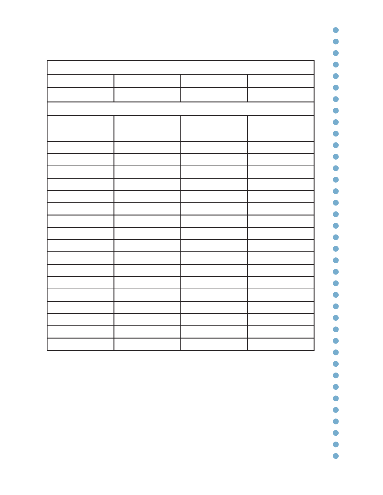
31
Service history
Installation
Technician Date Notes Signature
Maintenance
Technician Date Notes Signature
Page 32

32
Warranty conditions
This unit is guaranteed by BLUPURA for a period of two years from the date of
purchase.
The warranty entitles the owner to the free-of-charge repair of the unit by our
company or the free-of-charge replacement of any parts that have been shown to
have manufacturing defects.
The warranty does not include normal wear-and-tear to the components, or any
damage caused to the components due to negligent or improper use, or due to
a non-standard installation.
The warranty shall not be applicable if the unit has been tampered with or if
repairs have been carried out by unauthorized persons.
Page 33

Page 34

Page 35

160009 - Rev 01 - 23/04/2016 - 11:59
Page 36
Blupura srl
- Registered office -
Via F.lli Brancondi, 56
60025 Loreto (AN) Italy
- Headquarters -
Via Erideo Marinucci, 2/4
62019 Recanati (MC) Italy
Tel +39 071 9710080
Fax +39 071 9710084
[email protected]
www.blupura.com
 Loading...