


Laser module MZR.5300.01
Work steps should only be carried out by a licensed electrician!
Please keep a copy of the operating instructions.
EA
BA-117/1EA MZR.5300.01

Table of contents
Contents
A - Reading guide and safety instructions 3
B - Technical Data 5
C - Mechanical assembly of laser module 6
D - Electrical connection of laser module 8
E - Adjusting laser 11
F - Troubleshooting 12
G - Electrical circuit diagram 13
2 BA-117/1EA MZR.5300.01
A - Reading guide and safety instructions
A.1 - How to use these operating instructions
• Please keep a copy of the operating instructions.
• Before starting work, please read the installation instructions and follow all safety instructions.
A.2 - Safety instructions
• Work steps should only be carried out by a licensed electrician.
• Carefully read the operating instructions before laser module assembly.
• When using the MINIPRESS P or MINIDRILL P, the MINIPRESS P and MINIDRILL P operating instructions should be followed.
• When operating the laser module, please make sure that no one is within the projection area of the laser beam. Please also make
sure that unintentional, refl ected beams (e.g. from refl ective objects) can not intersect with any people in the area. Do not look
directly into the laser beam and never point it at a person. Lasers can cause eye and skin injuries. Never point the beam at mirrors
or refl ective surfaces. Uncontrolled, diverted beams may hit a person. Only operate the laser in a monitored area. The laser module
is not intended for children. Trained personnel are required to monitor the operation of the laser module in schools, training facilities,
hobby and self-help workshops.
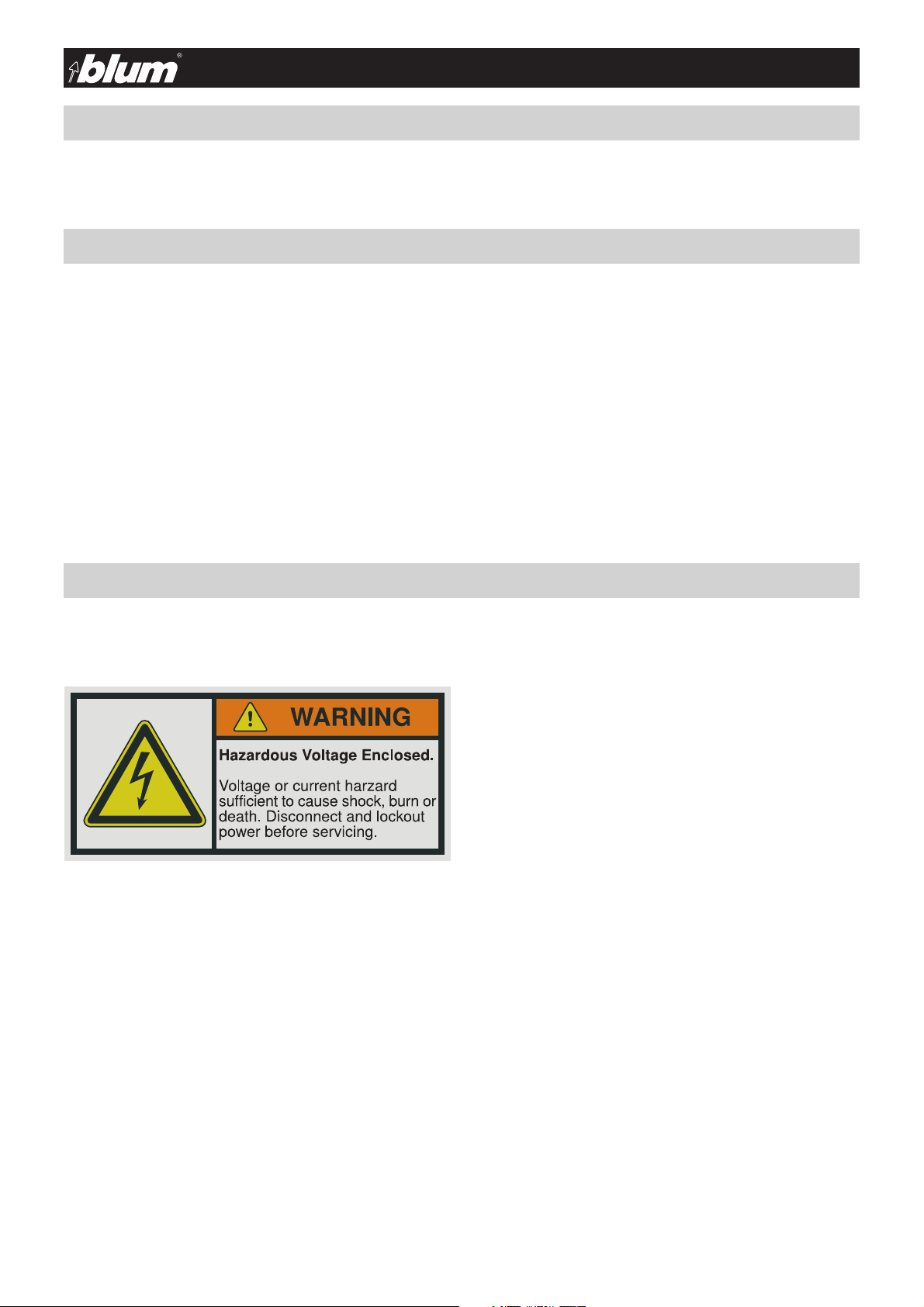
A.3 - Danger information
• The safety and danger information in the MINIPRESS P, MINIDRILL P operating instructions must be followed when starting up,
operating, retrofi tting, servicing, repairing and dismantling the MINIPRESS P, MINIDRILL P.
Please familiarise yourself the following safety information
before staring any electrical work. Electrical work should only be
carried out by a licensed electrician.
No one should deviate from the following instructions even if this
should cause the work to be more diffi cult, more expensive or
take longer:
Any person working on MINIPRESS P, MINIDRILL P electrical
parts is responsible for following all local codes and therefore,
may be liable for any damages.
• Never work on components or control unit parts that are still
energised. Always disconnect electrical power from machine
and set the main switch to 0 before starting work.
• Follow all LOCKOUT / TAGOUT procedures established by
management
• Always use a voltage tester to ensure that components as well
as control unit components are not energised before starting
work.
3 BA-117/1EA MZR.5300.01

A - Reading guide and safety instructions
• Never look directly into the laser beam. The laser can cause
eye damage
Safety information:
This exclamation point indicates important safety information that must be followed.
Comment:
This exclamation point indicates a comment. If this comment is not followed, then assembly machine components
!
as well as the work piece itself may be damaged or the assembly machine may be rendered inoperable and/or the
work piece unusable.
A.4 - Intended use
• The intended purpose of laser module MZR.5300 is measurement and position determination on the work piece in conjunction with
MINIPRESS P, MINIDRILL P. Only wood or particle board should be used as the work piece since they are non-refl ective. Coated
and/or refl ective work pieces may not be used. Laser module MZR.5300 may only be used in combination with MINIPRESS P,
MINIDRILL P in commercial and industrial applications. The manufacturer does not assume liability for uses not described in these
operating instructions or the MINIPRESS P, MINIDRILL P operating instructions.
4 BA-117/1EA MZR.5300.01

B - Technical data
B.2 - Technical data
• Length: 40 mm
• Diameter: 12 mm
• Diode power: 5 mW
• Operatind Distance: 250 mm
• Wavelength: 650 nm
• Operating voltage: 2.5 - 6 V DC
• Operating current: 30 mA
• Operating temperature: -10 - 40 °C
• Storage temperature: -40 - 80 °C
• Laser class: 2M
• Optics: acrylic lens
• Wirelength: 1510 mm
• Material of housing: aluminium
• Cable type: LifYY 2y 0.5 mm²
• fan angle: 90° or 60°
• line thickness: 0.5 mm @ 250 mm
• Potential of housing: VDD
5 BA-117/1EA MZR.5300.01

C - Mechanical assembly of laser module
C.1 - Standard components
• Wrench DIN EN 911 SW 2 mm
• Wrench with “T“ handle DIN EN 911 SW 3 mm
• Sub-assembly MZR.5300.01
• Power supply unit
• 1 screw DIN 912 M 4x16 (ASTM F 912M:2004 )
• Cable clips
• Label
C.2 - MINIPRESS P preparation
3.1
• Set main switch (3.1) to Pos.0
• Disconnect electrical and pneumatic connections from the machine
ATTEN TI ON:
The main switch does not disconnect the machine
from the air pressure system.
ATTEN TI ON:
gash injury.
• Remove all inserted drill bits
6 BA-117/1EA MZR.5300.01

C - Mechanical assembly of laser module
C.3 - Laser module assembly
• Insert mounting screw into the mounting hole on the backside
of gearbox housing and rotate the screw 2 turns clockwise
• Place the laser module on to the bolt slide to the right
• Temporarily tighten the screw using the allen key provided
7 BA-117/1EA MZR.5300.01

D - Electrical connection of laser module
D - Electrical connection of laser module
D.1 - Safety instructions / Preparation of MINIPRESS P or MINIDRILL P and control unit
• Never work on components or control unit parts that are still
energised. Always disconnect electrical power from machine
and set the main switch to 0 before starting work
• Follow all LOCKOUT / TAGOUT procedures establishment by
management
• Always use a voltage tester to ensure that components as well
as control unit components are not energised before starting
work
• Set main switch (3.1) to Pos.0
• Disconnect electrical and pneumatic connections from the assembly machine.
ATTEN TI ON:
3.1
The main switch does not disconnect the assembly machine
from the air pressure system.
D.2 - Retrofi tting the control unit
• Remove the screws of the control unit housing using a screwdriver.
• Turn the screws counter-clockwise
• Remove the control unit housing cover
8 BA-117/1EA MZR.5300.01

D - Electrical connection of laser module
!
• Snap the transformer into place on the DIN rail
• Mount the cable bushing
• Attach cable along the pneumatic lines using the cable ties • Feed the cable through the cable bushing
• Set aside enough remaining cable up to the cable tie
• Thread the cable as shown
9 BA-117/1EA MZR.5300.01

• Never work on components or control unit parts that are still
energised. Always pull the mains plug and set the main switch
to 0 before starting work
• Always use a voltage tester to ensure that components as well
as control unit components are not energised before starting
work
eludom resal fo noitcennoc lacirtcelE - D
• Connect the prepared quick-fi x connections
• Connect the laser diode to the low voltage side of the power
supply unit
• Put the label on the machine
• Carry out the steps in chapter E
• Replace the cover on the control unit housing
• Turn the screws clockwise using a screwdriver
10 BA-117/1EA MZR.5300.01

E - Adjusting laser
• Never look directly into the laser beam. The laser can cause
eye damage
• We recommend that you use laser protection glasses (DIN
207) when adjusting the laser
4.8
2.7
3.1
3.2
3.3
A
• Main switch (3.1) to pos. 1
• Laser line must be visible
ATTEN TI ON:
All items except for the work piece should be removed from the work
area of the assembly machine. Keep your hands out of work area (A)
E.1 - Adjusting laser to zero position
• Slightly loosen sub-assembly screw using a wrench (counterclockwise)
• Set laser line to the zero position
• Tighten screws using wrench (clockwise)
E.2 - Check the laser angle
• If laser angle is correct, all work steps are done. The machine
with the laser module is ready for work.
• If laser angle is wrong, carry out the steps in chapter F
11 BA-117/1EA MZR.5300.01
D - Electrical connection of laser module
F - Troubleshooting
• Never look directly into the laser beam. The laser can cause
eye damage
• We recommend that you use laser protection glasses (DIN
207) when adjusting the laser
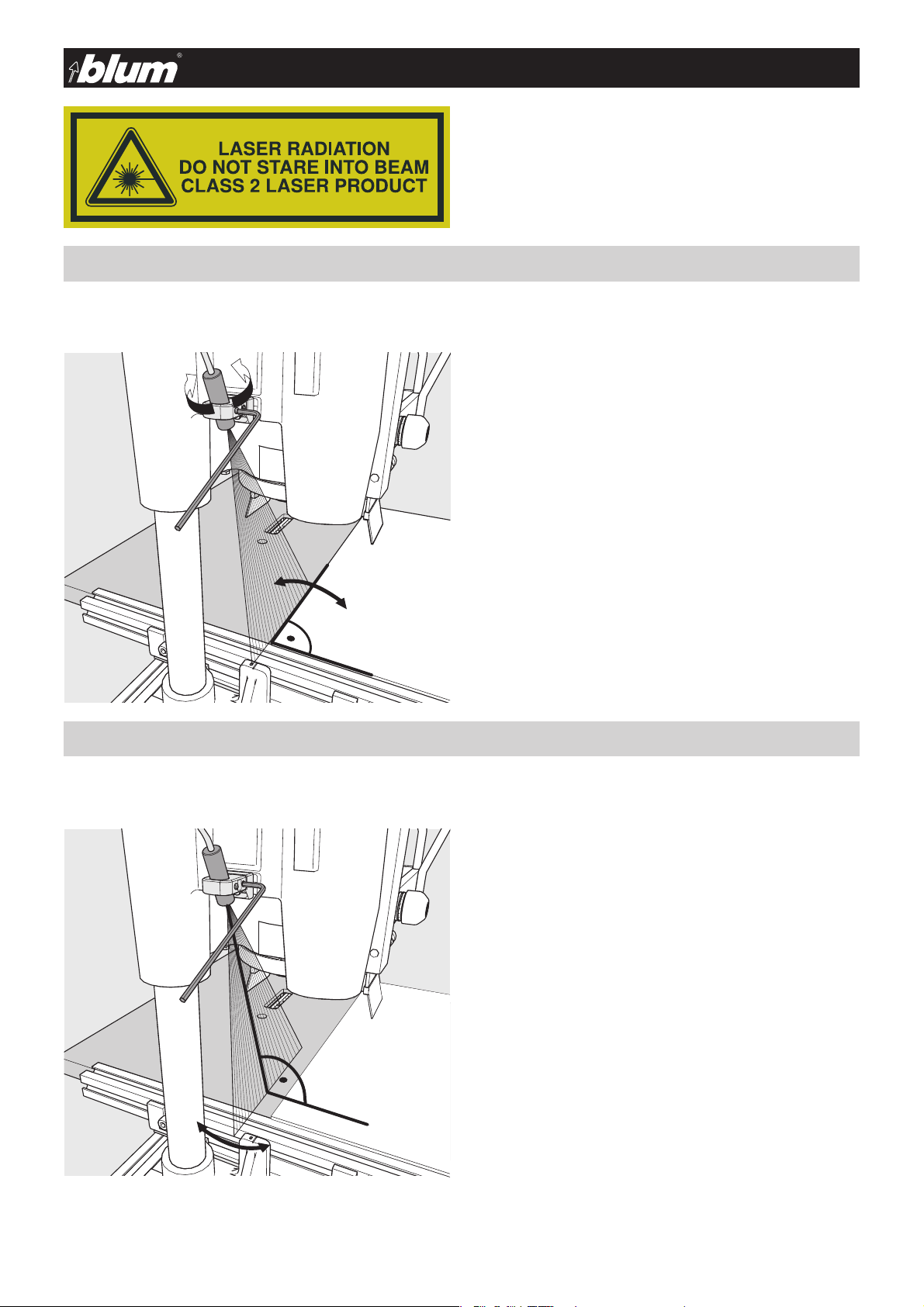
F.1 - Adjusting the laser angle
Only carry out the following steps when the laser angle is not correct
• Loosen set screw using allen key (counter-clockwise)
• Turn laser diode until the correct angle is reached on the work
piece or ruler. Use a work piece for the alignment. Affi x the
work piece to the work center using clamps
• Re-tighten set screw using allen key (clockwise)
F.2 - Laser beam is not perpendicular
Only carry out the following steps when the laser is not perpendicular
The laser beam is not perpendicular when it has moved from the zero position due to the stroke movement
• Loosen set screw using allen key (counter-clockwise)
• Move laser diode until the laser beam is perpendicular
• Re-tighten set screw using allen key (clockwise)
12 BA-117/1EA MZR.5300.01

D - Electrical connection of laser module
G - Diagrams
G.1 - Electrical diagram
S1
black
L1
white
N
green
PE
S1 690V IEC, 600V UL/CSA 4552380
F1 250V, dm5x20mm, 1.6AT 1788700
1S2 250V/6A, G1/4" 3988890
H1 230VAC 2456160
K1 400V (max.690V), 12A 2456300
M1 1,1kW, 220V/60Hz 3244009
C 25µF, 400VDB 2649801
1
2
3
4
6
5
8
7
T1,6A
1S2
F1
1
P
2
4
PE
0V 220V~
NL
T1
-+
POTENTIOMETER
0V3,6V
brown
blue
H1
X1
A1
1
35
13
K1
X2
A2
246
U1
V1
C
W1
14
W2
U2
V2
1x220V 60Hz
S6-60%ED
7,3A, 1,1kW, 3325/min
M1
1~
C 25µF 400VDB
13 BA-117/1EA MZR.5300.01
 Loading...