


AVENTOS HK-S
Subject to technical modifications without notice. © 2015
1
Lift mechanism set
Set includes:
▀
Lift mechanism (qty 2)
▀
Cover plate (left and right)
Also includes:
▀
SCHR 4X35 — #7 x 35 mm (1-3/8”)
wood screw (qty 10)
Power factor Opening angle Part no.
19 — 39 107°
20K2B00.N1
40 — 85 107°
20K2C00.N1
86 — 177 107°
20K2E00.N1
Wood or wide aluminum door mounting plate
▀
W o o d o r w i d e a l u m i n u m m o u n t i n g p l a te ( q t y 2 )
Part no.
Wood or wide aluminum mounting plate
175H3100
Installation screw for wood doors
606N or 606P
Installation screw for wide alum doors
7072A
Narrow aluminum door mounting plate
▀
N a r ro w a l u m i n um mo u n t in g p l a t e (q t y 2)
(for use with AVENTOS HK-S only)
▀
Includes 699.1100 installation screws (qty 4)
Part no.
Narrow aluminum mounting plate
20K4A00A02
Recommended parts for tension adjustment
Use of a POZI bit insert and bit holder is recommended when adjusting the tension of the
lift mechanism.
Part no.
#2 x 2" POZI bit insert
POZI BIT #2x2
1/4" bit holder
BIT HOLDER
Required parts
Assembly instructions
Subject to technical modifications without notice. © 2015
2
Z
64
52
5 min.
5
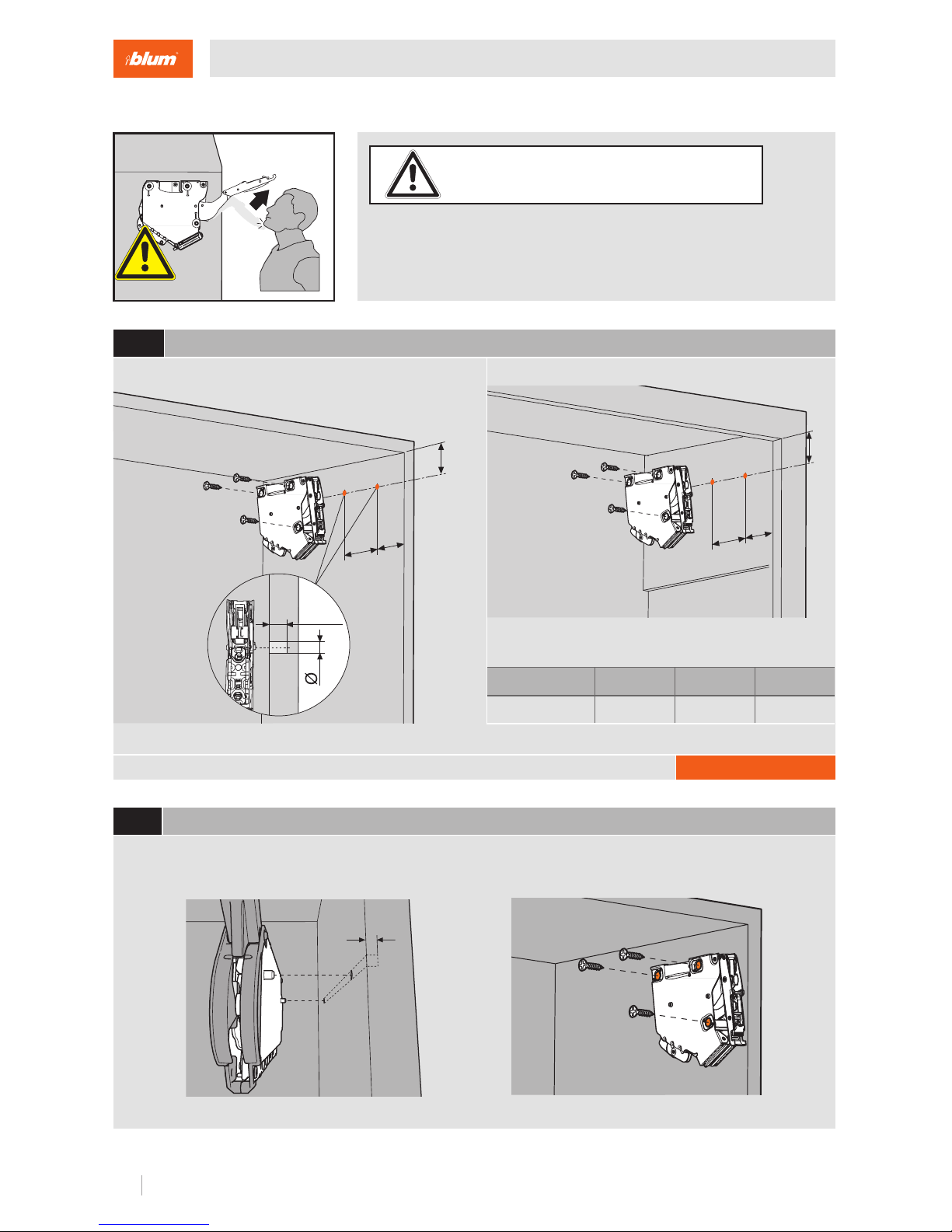
Universal individual template is available for pre-boring locating pins
WARNING
1
Locating pin locations and minimum depth
Part no.
65.1051.02
2
Attaching the lift mechanism
Z
64
52
Panel Face frame
Overlay up to 20
24 26
Z
37 35.5 34.5
NOTE: Face frame cabinets must be blocked
out flush with the frame.
Assembly
Risk of injury from spring-loaded arm
▀
Do not push arm assembly down or leave in the down position
▀
Remove mechanism before installing or removing cabinet
5 min.
Ø5
Align the lift mechanism in the cabinet using the 5 mm locator pins and attach the mechanism with the three
wood screws provided.
#7 x 35 mm (1-3/8") wood screws (qty 3)
Subject to technical modifications without notice. © 2015
3
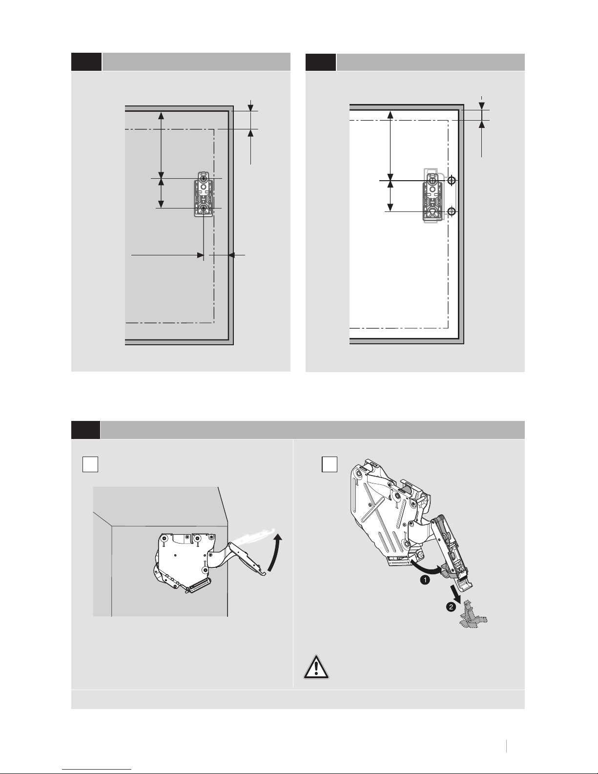
Narrow aluminum frame doors
3b
Wood/wide aluminum frame doors
3a
NOTE: Attach each mounting plate with two 606N or 606P wood screws for wood doors, two
7072A screws for wide aluminum doors or two 699.110 screws for narrow aluminum doors
Overlay
12.5 + Overlay
32
58
+
Overlay
Overlay
31
56
+
Overlay
Attaching the mounting plates
Risk of injury from spring-loaded arm.
Standing at arm’s length carefully raise the
arm to the upright position.
For the 20K2B00.NA, carefully
remove the plastic tab .
4
Raise lever arm assembly with caution
NOTE: Do not remove plastic tab until just before attaching the door
A
B
Subject to technical modifications without notice. © 2015
4
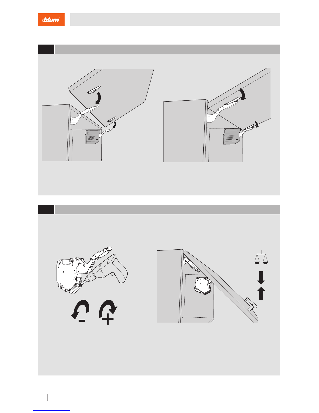
Use a screw gun, POZI driver bit insert and bit holder to adjust each lift mechanism to the
desired tension.
Attach the door using the CLIP mechanism in the mounting plate.
5
Attaching the door
6
Adjust the door tension
Assembly

Subject to technical modifications without notice. © 2015
5
Place the left and right cover plates over the appropriate lift mechanisms and snap them in place.
Use a POZI screwdriver on cam adjustments for each of the three 3-dimensional adjustments.
7
Finalize the door adjustments
8
Attach cover caps
± 2 mm
± 2 mm
± 2 mm

Subject to technical modifications without notice. © 2015
6
WARNING
▀
Disengage the CLIP mechanism of the lever arm from the mounting plate
▀
Support the door with one hand and repeat on the other side
1
Removing the door
Remove the cover plate.
2
Removing the covers
Removal
Risk of injury from spring-loaded arm
▀
Do not push arm assembly down or leave in the down position
▀
Remove mechanism before installing or removing cabinet

Door thickness
16 19 22 26
X
70 59 49 35
door height
door thickness
X
107
Other information
Blum, Inc.
800-438-6788
sales.us@blum.com
blum.com
Subject to technical modifications without notice. © 2015 INST-AVT12-04.15
Inch mm
1
/
32
.031 1
1
/
16
.063 1.5
3
/
32
.094 2
1
/
8
.12 5 3
5
/
32
.15 6 4
3
/
16
.18 8 5
7
/
32
.219 5.5
1
/
4
.25 6
9
/
32
.281 7
5
/
16
.313 8
11
/
32
.344 9
3
/
8
.375 9.5
13
/
32
.406 10
7
/
16
.438 11
15
/
32
.469 12
1
/
2
.5 13
17
/
32
.531 13.5
9
/
16
.563 14
19
/
32
.594 15
5
/
8
.625 16
21
/
32
.656 17
11
/
16
.688 17. 5
23
/
32
.719 18
3
/
4
.75 19
25
/
32
.781 20
13
/
16
.813 20.5
27
/
32
.844 21
7
/
8
.875 22
29
/
32
.906 23
15
/
16
.938 24
31
/
32
.969 24.5
1 1 25.4
Panel and Face frame clearance
 Loading...