


AT6020
Commercial Fertilizer Injection Applicator
TM
Assembly
and Operators
Manual
Manual Number
0606020
Rev. 2-19-18 $20.00 Net.

Thurston Manufacturing Company • 1708 H Ave • Box 218 • Thurston, Nebraska, 68062-0218
Phone: 402-385-3041 • E-mail: box218@thurstonmfgco.com
Design specications and features as described are subject to change without notice. BLU-JET is a registered trademark of Thurston Manufacturing Company, Thurston NE.
/BLU-JET
@BLU-JET01
/SIronWorks
@SIronWorks

Table of Contents
AT6020
Manual Number:
0606020
Rev. 2-19-18
Introduction------------------------------------------------------------------------------------------------------- 1
Deliver--------------------------------------------------------------------------------------------------------------- 4
To The Owner----------------------------------------------------------------------------------------------------- 5
Warranty------------------------------------------------------------------------------------------------------------ 6
Safety--------------------------------------------------------------------------------------------------------------- 7
Operating Instructions---------------------------------------------------------------------------------------- 11
Anhydrous Ammonia Operating Instructions--------------------------------------------------------- 19
Coupler Operation---------------------------------------------------------------------------------------------- 22
Parts----------------------------------------------------------------------------------------------------------------- 23
Emergency Fresh Water Tank--------------------------------------------------------------------------------- 23
Operational Guide For Various Residue Situations BLU-JET StripTill Implement--------------- 24
Center Section Bundle 66000103 Parts List--------------------------------------------------------------- 35
Primary Wing Right-hand Bundle 66000103--------------------------------------------------------------- 40
Primary Wing Left-hand Bundle 66000103----------------------------------------------------------------- 42
Center Section Bundle 66000103 Exploded Views------------------------------------------------------- 44
Center Section Bundle 66000103 Depth Control Parts-------------------------------------------------- 48
Secondary Wing Right-hand With Hydraulic Gauge Wheel Bundle 66000107-------------------- 50
Secondary Wing Left-hand With Hydraulic Gauge Wheel Bundle 66000107---------------------- 52
Dual Wheel Lift Bundle 66000105---------------------------------------------------------------------------- 54
Pin Adjust Gauge Wheel Bundle 55000100---------------------------------------------------------------- 56
48’ and 60’ Complete Toolbar Drawings--------------------------------------------------------------------- 57
Hydraulics 60’------------------------------------------------------------------------------------------------------ 58
Hydraulics 48’------------------------------------------------------------------------------------------------------ 63
Third Wing Bundle 66000108 Left Side--------------------------------------------------------------------- 70
Third Wing Bundle 66000108 Right Side------------------------------------------------------------------- 72
Stagger Brackets Offset 6 x 6 Mounting-------------------------------------------------------------------- 74
Stagger Bracket 40 x 48 Double, (AAM2125)------------------------------------------------------------- 75
Offset Stagger Bracket (AAM2136)-------------------------------------------------------------------------- 76
Super 1200 Flex Coulter and Shank------------------------------------------------------------------------- 77
Nurse Tank Hitch Assembly PKG00234--------------------------------------------------------------------- 78
Nurse Tank Hitch Assembly, Low Mounting PKG00247------------------------------------------------- 79
Auto-Lok Nurse Tank Hitch (AAM2831)-------------------------------------------------------------------- 80
Blades---------------------------------------------------------------------------------------------------------------- 82
SealPro ll and SealPro SKF------------------------------------------------------------------------------------ 83
Hitches--------------------------------------------------------------------------------------------------------------- 90
Jack------------------------------------------------------------------------------------------------------------------ 91
Shanks-------------------------------------------------------------------------------------------------------------- 92
Row Clamps------------------------------------------------------------------------------------------------------- 93
Manual Holder----------------------------------------------------------------------------------------------------- 96
Impellicone Mounting Hardware------------------------------------------------------------------------------ 97
SuperShooter------------------------------------------------------------------------------------------------------ 98
SuperShooter III Add-on Parts (66000136) Single Assembly------------------------------------------ 100
SuperShooter III Add-on Parts (66000137) Dual Assembly------------------------------------------- 102
GDI With Pump Distribution (Rear Mount) (Bundle 20200119)---------------------------------------- 104
Heat Exchanger (CCP2755)----------------------------------------------------------------------------------- 107
GDI WithTwin Pump Distribution (Rear Mount)(Bundle 20200121)---------------------------------- 112
Meter Assembly Impellicone Manifolds--------------------------------------------------------------------- 121
MaxPac AR700 Parts and Assembly------------------------------------------------------------------------ 131
MaxPac Basket Mount Arm------------------------------------------------------------------------------------ 132
Coulter Extension Kit (9-7/8”)----------------------------------------------------------------------------------- 133
MaxPac Assembly------------------------------------------------------------------------------------------------- 134
Torsion Arm Basket Parts---------------------------------------------------------------------------------------- 136
Torsion Arm Assembly-------------------------------------------------------------------------------------------- 137
Torsion Arm Mounting Bracket Rigid Fertilizer Row------------------------------------------------------ 138
Basket Mount Flat With Hardware---------------------------------------------------------------------------- 139
Decals---------------------------------------------------------------------------------------------------------------- 140
StripTill Residue Manager Parts------------------------------------------------------------------------------- 141
Coulter Shank Extensions Brackets-------------------------------------------------------------------------- 142
StripTill Residue Manager Assembly------------------------------------------------------------------------- 143
Light Kit/Slow Moving Vehicle--------------------------------------------------------------------------------- 149
Light Kit/Slow Moving Vehicle 20” Row Spacing---------------------------------------------------------- 151
GDI Lift Kit---------------------------------------------------------------------------------------------------------- 153
Hub and Spindle Assembly------------------------------------------------------------------------------------- 154
Hydraulic Repair Kit---------------------------------------------------------------------------------------------- 160
Tie-rod Cylinder Disassembly-Assembly Procedure----------------------------------------------------- 161
Torque Specications-------------------------------------------------------------------------------------------- 162
Specications------------------------------------------------------------------------------------------------------ 163
Assembly................................................................................................................................ 165
Main Frame and Primary Wings------------------------------------------------------------------------------ 165
Secondary Wings------------------------------------------------------------------------------------------------- 166
Dual Wheel Lift----------------------------------------------------------------------------------------------------- 168
Primary Wing Gauge Wheels----------------------------------------------------------------------------------- 171
Center Section Wheel Lift Linkage--------------------------------------------------------------------------- 175
Tongue Mounting------------------------------------------------------------------------------------------------- 177
Tongue Linkage--------------------------------------------------------------------------------------------------- 178
Bolt-on Cylinder Lug--------------------------------------------------------------------------------------------- 181
Primary Wing Cable Release---------------------------------------------------------------------------------- 182
Hitch and Safety Chain------------------------------------------------------------------------------------------ 183
Jack------------------------------------------------------------------------------------------------------------------ 184
Hose Holder and Hose Tender-------------------------------------------------------------------------------- 185
Turnbuckle Wrench----------------------------------------------------------------------------------------------- 186
Hitch Storage------------------------------------------------------------------------------------------------------ 187
Manual Holder----------------------------------------------------------------------------------------------------- 188
Stagger Brackets-------------------------------------------------------------------------------------------------- 189
Primary Wing Linkage------------------------------------------------------------------------------------------- 190
Secondary Wing Linkage--------------------------------------------------------------------------------------- 191
Third Wing Linkage----------------------------------------------------------------------------------------------- 193
Secondary Wing Latch Standard Wing---------------------------------------------------------------------- 194
Hose Holder Placement 60’------------------------------------------------------------------------------------- 195
Hydraulics 60’ Assembly------------------------------------------------------------------------------------------ 196
Depth Control Parts and Assembly---------------------------------------------------------------------------- 201
Hydraulic Hoses 60’ Assembly--------------------------------------------------------------------------------- 210
Hose Holder Placement 48’------------------------------------------------------------------------------------- 218
Hydraulics 48’ Assembly----------------------------------------------------------------------------------------- 220
Hydraulics Hoses 48’ Assembly------------------------------------------------------------------------------- 222
Nurse Tank Hitch Single PKG00234------------------------------------------------------------------------- 234
Nurse Tank Hitch Single Low Mounting PKG00247------------------------------------------------------ 236
SuperShooter III Add-on Parts (66000136) Single Assembly------------------------------------------ 238
SuperShooter III Add-on Parts (66000137) Dual Assembly------------------------------------------ 242
Swing Adjust Gauge Wheel------------------------------------------------------------------------------------ 246
Coulter--------------------------------------------------------------------------------------------------------------- 247
Shank---------------------------------------------------------------------------------------------------------------- 249
Spring Cushion---------------------------------------------------------------------------------------------------- 251
Light Kit & Slow Moving Vehicle------------------------------------------------------------------------------ 253
Light Kit & Slow Moving Vehicle 20” Row Spacing------------------------------------------------------- 258
Safety Tank--------------------------------------------------------------------------------------------------------- 261
Depth Collars------------------------------------------------------------------------------------------------------ 262
Decals--------------------------------------------------------------------------------------------------------------- 263
Hydraulic System Charging------------------------------------------------------------------------------------ 265
Folding Tool Bar--------------------------------------------------------------------------------------------------- 266
Row Spacing Layout------------------------------------------------------------------------------------------- 267
1

AT6020
Introduction
Welcome to Thurston Manufacturing Company. Our goal is to provide
quality products and services to our customers. The company’s BLU-JET
products have a reputation for quality, excellence in design and proven
durability. Energetic, resourceful and continuous improvement goals in
Environmental, Safety, Quality, Production and Engineering keep our
rm at the cutting edge of technology.
We hope your BLU-JET equipment will give you years of service.
Read this manual carefully. It will instruct you on how to operate and
service your machine safely and correctly. Failure to do so could result
in personal injury and/or equipment damage.
SAFETY INFORMATION
Indicates an imminently hazardous situation that, if
not avoided, will result in death or serious injury.
The sign will have the color combination of red and
white.
Indicates a potentially hazardous situation that, if
not avoided, could result in death or serious injury.
The sign will have the color combination of orange
and black.
Indicates a potentially hazardous situation that, if
not avoided, may result in minor or moderate injury.
The sign will have the color combination of yellow
and black.
NOTE: Indicates a special point of information.
Carefully read and follow all safety signs. Reinstall safety signs that
are damaged or missing.
DANGER
WARNING
CAUTION
Right-hand and left-hand sides of the implement are determined by
facing in the direction the implement will travel when going forward.
2

AT6020
Introduction
General Information:
The BLU-JET AT6020 Commercial Class Fertilizer Injection Applicator
achieves a new performance dimension for high acre, high rate applications.
The BLU-JET AT6020 can easily be congured for a number of operations
including Pre-Plant, Side-Dress, and StripTill applications with anhydrous,
liquid, dry, or dual placement fertilizer injection.
The AT6020 was designed to be used in combination with BLU-JET’s
Super 1200 Coulter, MaxPac 700 AutoReset shank mounting, residue managers,
SealPro disc sealers, torsion arm rming baskets and BLU-JET’s complete
line of shank mountings.
Warranty is provided for customers who operate and maintain their equi pme nt
as described in this manual. Warranty registration is accomplished by
the dealer completing and forwarding the WARRANTY REGISTRATION FORM
to Thurston Manufacturing Company. It is in your best interest to ensure that
this has been done.
For your convenience we have four easy ways to register your warranty.
• Call our toll free number and ask for warranty registration.
1-800-658-3127
• Register on-line at: www.BLU-JET.com
• Complete and mail this Product Registration form to:
Attn: Thurston Manufacturing Company
Product Registration
PO Box 218
Thurston, NE. 68062
• Email a copy to: warranty@thurstonmfgco.com
Thurston Manufacturing Company Warranty does not cover the following:
1) Cleaning, transporting, mailing and service call charges.
2) Depreciation or damage caused by normal wear, accidents,
improper protection or improper use.
The Serial Number
is located from the
rear of the tool bar
on the right-hand
side behind the
Tractor side
Record your implement model and serial number in the space provided below.
Your dealer needs this information to give you prompt, efcient service when
you order parts.
MODEL NO.__________________________
SERIAL NO.__________________________
DATE PURCHASED___________________
tongue pull plate.
3

AT6020
Dealer Checklist
To The Dealer:
Inspect the implement thoroughly after assembly to be certain it is
functioning properly before delivering it to the customer. The following
checklist is a reminder of points to cover. Check off each item as it is
found satisfactory or after proper adjustment is made.
PRE-DELIVERY CHECKLIST
1. All hardware properly tightened
2. Lubrication of grease ttings
3. All decals properly located and readable
4. Other adjustments for machine level height, etc.
5. Overall condition (touch up any scratches, clean and
polish)
6. Operator’s manual
DATE SET UP_______________________________
SIGNATURE________________________________
DELIVERY
Review the operator’s manual with the customer. Explain
the following:
1. Safe operation and service
2. Correct machine installation and operation
3. Daily and periodic lubrication and maintenance
4 Daily and periodic inspections
5. Trouble shooting
6. Storing machine
7. Thurston Manufacturing Company parts and service
8. Have the customer write the machine model and serial
number in space provided in manual introduction.
9. Give customer the operator’s manual and encourage
the customer to read the manual carefully.
10. Completion and mailing of warranty registration
form.
DATE DELIVERED__________________________
SIGNATURE_______________________________
MODEL NO.________________________________
SERIAL NO.________________________________
4

AT6020
To The Owner
Thank you for your recent purchase of a new BLU-JET
implement. The primary objective of Thurston Manufacturing
Company is to build and provide you with a quality product.
However, in the event that a problem does occur, it is imperative
that your warranty registration is on le in order to accurately
respond to your specic service circumstances.
For your convenience we have four easy ways to register
your warranty:
For your convenience we have four easy ways to register your warranty.
• Call our toll free number and ask for warranty registration.
1-800-658-3127
• Register on-line at: www.BLU-JET.com
• Complete and mail this Product Registration form to:
Attn: Thurston Manufacturing Company
Product Registration
PO Box 218
Thurston, NE. 68062
• Email a copy to: warranty@thurstonmfgco.com
This manual has been prepared to assist you in the assembly
of your new machine and contains information pertaining to
safety, operations and all of its parts. Our personnel in sales
and service are always available to assist you when questions
arise concerning the assembly or operations of your tool bar.
When ordering parts, please refer to part numbers and
descriptions as listed throughout this book. All parts and
whole goods will be shipped FOB Thurston, Nebraska. Or
FOB your regional distributor. Always check merchandise
immediately upon receipt for damage or shortage. Note any
discrepancy on carrier’s bill of lading and notify Sender within
10 days. Returned goods will be subject to a 15% restocking
charge. Thurston Manufacturing Company reserves the right
to make improvements and modications on equipment
without obligation to change previously built equipment. All
prices are subject to change without notice.
5

AT6020
Limited Warranty
Thurston Manufacturing Company warrants each new BLU-JET machine
primary framework to be free from defects in material and workmanship for a period
of ve (5) years, normal wear of wearing parts excepted. Thurston Manufacturing
Company further warrants each new BLU-JET product to be free from defects in
material and workmanship, normal wear of wearing parts excepted, for a period
of one (1) year. All accessories purchased and resold by Thurston Manufacturing
Company will be warranted according to their respective manufacturer. Tires on
BLU-JET equipment are warranted through their respective tire manufacturers and
their network of dealers in your local area.
Warranty begins from date of delivery to the original purchaser and applies
to all new BLU-JET products that have not been altered and are being used for the
intended purpose. Negligence, abuse or modication of equipment manufactured
by or purchased and resold by Thurston Manufacturing Company will void this
warranty.
The obligation of Thurston Manufacturing Company to honor this warranty
is limited to the repair or replacement of defective merchandise, to the original
purchaser, subject to inspection of equipment in question by an authorized Thurston
Manufacturing Company sales or service technician. In the USA, freight of warranty
replacement parts including main frame centers and wings will be prepaid for a
period of one (1) Year by Thurston Manufacturing Company. Shipments of repaired
or replaced parts including main frame centers and wings after one year will be paid
by the customer.
Return of defective goods must be made within thirty (30) days of failure to
Thurston Manufacturing Company, Thurston, Nebraska USA or to the nearest
authorized BLU-JET Distributor or Rep Sales and service outlet.
Thurston Manufacturing Company will not be held responsible for any repair
charges made by customers without prior written consent and prior equipment
inspection by an authorized Thurston Manufacturing Company sales or service
technician.
This warranty shall not be interpreted to render liability for injury or damages
of any kind, direct, consequential or contingent to person or property. This warranty
does not extend to loss of crops, economic and/or commercial loss, loss because
of delay in crop production or any expense incurred for labor, supplies, substitute
machinery, rental or for any other reason. This warranty is subject to any existing
condition of supply, which may directly affect Thurston Manufacturing Company’s
ability to obtain materials of manufacture and delivery of replacement parts.
Thurston Manufacturing Company reserves the right to make improvements
in design and changes in specications at any time without incurring any obligation
to owners of units previously sold.
No one is authorized to alter, modify or enlarge this warranty nor its exclusions,
limitations and reservations. Thurston Manufacturing Company makes no
representations or warranties, expressed or implied (including implied warranties
of merchantability and tness), except for those set forth in Thurston Manufacturing
Company’s current applicable published warranty policies and procedures.
Layton W. Jensen, President 022398\mgmt
6

AT6020
Safety
RECOGNIZE SAFETY INFORMATION
• This is the safety-alert symbol. When you see his symbol
on your machine or in this manual, be alert to the
potential for personal injury. Follow recommended
precautions and safe operating practices.
FOLLOW SAFETY INSTRUCTIONS
• Carefully read all safety messages in this manual and
on your machine safety signs. Keep safety signs in good
condition. Replace missing or damaged safety signs.
• Learn how to operate the machine and how to use
controls properly.
• Do not let anyone operate without instruction.
• Keep your machine in proper working condition.
• Unauthorized modication to the machine may
impair the function and/or safety and affect machine life.
PROTECT CHILDREN AND BYSTANDERS
• Before you back, LOOK CAREFULLY behind for
children.
• Clear area of children, pets and bystanders.
HIGHWAY AND TRANSPORT OPERATIONS
Adopt safe driving practices:
• Keep the brake pedals latched together at all times.
NEVER USE INDEPENDENT BRAKING WITH MACHINE
IN TOW AS LOSS OF CONTROL AND/OR UPSET OF
UNIT CAN RESULT.
• Always drive at a safe speed relative to local
conditions and ensure that your speed is low enough
for a emergency stop to be safe and secure. Keep
speed to a minimum.
• Reduce speed prior to turns to avoid the risk of
overturning.
• Avoid sudden uphill turns on steep slopes.
• Always keep the tractor or towing vehicle in
gear to provide engine braking when going downhill.
Do not coast.
• Do not drink and drive.
• Comply with state and local laws governing highway
safety and movement of farm machinery on public roads.
• Use approved accessory lighting and necessary
warning devices to protect operators of other vehicles
on the highway during daylight and nighttime transport.
• The use of ashing amber lights is acceptable in most
localities. However, some localities prohibit their use.
Local laws should be checked for all highway lighting
and marking requirements.
• When driving the tractor and equipment on the road
or highway under (20 mph max.) (32 kmph max.) at night or
during the day, use ashing amber warning lights
and a slow moving vehicle (SMV) identication emblem.
7

AT6020
Safety
HIGHWAY AND TRANSPORT OPERATIONS
• Plan your route to avoid heavy trafc.
• Be a safe and courteous driver. Always yield to oncoming
trafc in all situations, including narrow bridges,
intersection, etc.
• Be observant of bridge loading ratings. Do not cross
bridges rated lower than the gross weight at which you
are operating.
• Always operate equipment in a position to provide
maximum visibility at all times. Makes allowances for
increased length and weight of the equipment when
making turns, stopping the unit, etc.
TRANSPORT SAFETY
• A safety chain will help control drawn equipment
should it accidentally separate from the drawbar.
• Attach the chain to the tractor drawbar support or
other anchor location. Provide only enough slack in
the chain to permit turning.
• Use hydraulic cylinder transport lockup during road
transportation.
• Maximum road speed is 20 m.p.h.
AVOID HIGH PRESSURE FLUIDS
• Escaping uid under pressure can penetrate the skin
causing serious injury.
• Avoid the hazard by relieving pressure before
disconnecting hydraulic or other lines. Tighten
all connections before applying pressure.
• Search for leaks with a piece of cardboard.
• Protect hands and body from high pressure uids.
• If an accident occurs, see a doctor immediately.
DISPOSE OF FLUIDS PROPERLY
• Improperly disposing of uids can harm the
environment and ecology. Before draining any
uids, contact your local environmental agency
for the proper waste disposal methods.
• Use proper container when draining uids. Do
not use food or beverage containers that may
mislead someone into drinking from them.
• DO NOT pour oil into the ground, down a drain, or
into a stream, pond, or lake. Observe relevant
environmental protection regulations when disposing
of oil and other harmful waste.
8

AT6020
Safety
Observe Safety Signs
AP 2234-7-98
AP 2483-8-98
AP 2914
AP 222 8-90
AP 2469-7-98
9

AT6020
Safety Decals
AP2972
AP2227
AP2974
AP2973
AP2975
10

AT6020
Operating Instructions
Hitch
NOTE:
Implement
hitch weights
are designed
to match
tractor size
ranges.
Check the
following
chart to
conrm your
particular
implement
specication.
Tractor to
tool bar
connection
1. The tractor must be equipped
with a drawbar and a draw bar safety chain clevis. For
rigid frame tractors equipped
with swinging drawbar, the
drawbar must be located in a
xed position in the center of
the tractor. Refer to your
tractor operators manual for
drawbar adjustment and
drawbar operating instructions.
Engine
Category
2. Before connecting the tool bar to the tractor drawbar, raise the
tractor three point hitch (if equipped) to prevent interference
between the implement and the tractor.
Connect the tool bar to tractor drawbar ONLY. DO NOT connect
the tool bar to any other part of the tractor. Connect the tool bar
clevis to the tractor drawbar with hitch pin. Install the safety
chain through the tractor drawbar support bracket.
I
II
III
IV
HP Range
20
40
80
100
47
133
227
400
Generic Photo
Drawbar
Vertical Load Pounds
731
1,236
2,248
4,777
1,405
3,597
5,957
10,341
Safety
hitch pin
Safety
chain
3. Always use a safety hitch pin of the correct diameter. Make sure
that the hitch pin is locked in place with a safety type lock pin or
other locking device.
4. Always use a safety chain between the toolbar and the tractor.
Install the chain to the tractor drawbar support bracket. Support
the center of the chain with a clevis installed to the tractor
drawbar.
WARNING: In case the tractor hitch pin is lost during transport-
WARNING
ing. The safety chain must be attached between the implement
and tractor to prevent separated implement from running freely
and causing damage or injury.
WARNING: Do not move articulated tractor steering wheel
WARNING
until everyone is clear of the equipment. Moving the steering
wheel can swing or move attached equipment which could
cause serious personal injury.
WARNING: Tractor drawbar must be in a xed position before
WARNING
transporting implement. Implement will sway or slam against
tractor resulting in equipment damage or injury to personnel.
11

AT6020
Operating Instructions
Remote
hydraulic
NOTE:
Always
connect the
hoses so
the toolbar
raises when
the tractor
remote control lever is
moved rearward and
lowers when
the lever
is moved
forward.
Remote
hydraulic
5. Connect the toolbar hydraulic
hoses to the tractor remote
couplers. The 1/2” hoses
supply oil to the toolbar lift
cylinders. The 3/8” hoses
supply oil to the wing fold
cylinders.
6. It may be necessary to tie
the hydraulic hoses up to
keep them away from the
hitch area. A tarp strap
around the hoses and
between the two point arms
works well.
WARNING
WARNING: Hydraulic uid escaping under pressure can have
enough force to penetrate the skin. Hydraulic uid may also
infect a minor cut or opening in the skin. If injured by escaping
uid, see doctor at once. Serious infection or reaction can result
if medical treatment is not given immediately. Make sure all
connections are tight and that hoses and lines are in good
condition before applying pressure to the system. Relieve all
pressure before disconnecting the lines or performing other work
on the hydraulic systems.
Attaching
electrical
harness
Jack stand
7. Attach 7 pin electrical
harness before road
transport.
8. Lower the jack and pull
ring on drop leg jack
plunger and raise the sand
pad off the ground. Secure
plunger in holes.
I
MPORTANT: Always lower the
jack stand to the ground before
disconnecting the tool bar from the
tractor.
Ring
12

AT6020
Operating Instructions
Leveling
Machine
9. Before leveling the machine
the tire pressure should be
checked.
Inate center section lugged
tractor tires to 56 P.S.I. Maximum
Truck tires 95 P.S.I. Maximum
Before beginning operation of
this machine the main frame
must be level.
Place tool bar on level surface.
Use the turnbuckle wrench to
loosen the lower turnbuckle
jam nut. Adjust turnbuckle with
wrench until the main frame is
level front to back. After making
the necessary adjustment,
lock turnbuckle with jam nut.
Jam Nut
Main Frame
CAUTION
CAUTION: To prevent serious accident or injury
do not remove wing latch cable release mechanism. Wing fall may result during road transport.
10. Unlatch primary wing latch
with the cable release located
on the front of the tool bar
before unfolding tool bar.
NOTE: Cable must be free. Do not place
hydraulic hoses, EVA hoses or ties around
the cable.
13

AT6020
Operating Instructions
Leveling
adjustable
gauge
wheels
NOTE:
Adjust until
tool bar is
level
across the
entire bar
NOTE:
Coulter will
require
nal
working
depth
adjustment
in the eld.
11. Check tire pressure before
adjusting.
Loosen the two 1” x 4” Hex bolts
at the top of the adjust linkage.
Loosen 1” hex nut on inside of
threaded rod. Turn 1” hex nut
on outside clockwise to lower
wing and counter clockwise to
raise wing. Secure both nuts on
threaded rod against cylinder
lug adjust. Tighten
1” x 4” hex cap screws after
wheel adjustment.
Tighten one inch
hex nuts after
wheel adjustment.
Cylinder lug adjust
One Inch hex nut
14
Pin adjust
gauge
wheel
Depth
collars
12. Adjust pin adjust gauge wheel
to level position with the
hydraulic gauge wheel.
13. Install equal lengths of cylinder
depth collars to the right and left
hand center section wheel lift
cylinders.
NOTE: Unequal depth collar installation
may result in wheel lift linkage damage.

AT6020
Operating Instructions
LOCKED POSTION
DEPTH ADJUSTMENT
1. One complete revolution equals 1/2” of
depth increase.
LOCKING DEPTH ADJUSTMENT
LINKAGE
1. Rotate depth control adjuster latch
over handle and lock in place with
(27) (BP3376) 1/4” x 2” wire retaining
pin.
15

AT6020
Operating Instructions
Nurse tank
hitch
NOTE:
Periodically
check Latch
mechanism to
ensure proper
latching in the
extended
position.
Secondary
wing latch
14. Nurse tank hitch can be
retracted and moved from
side to side for easy hookup.
Hitch will automatically lock
in the extended position.
WARNING
Pinch point
To prevent Injury
Keep hands clear
when extending or
retracting the swing
slide insert
15. Mechanism must swing
freely in order to operate
properly. Installed position
must be squared with frame
to allow maximum freedom
of movement. Keep soil and
debris from area to allow
maximum movement.
16
Latch in open position
before wing is folded
Cylinder rod
maintenance
NOTE: After seasonal storage,
check wing latch for freedom of
movement.
16. All exposed cylinder rods
should be greased before
seasonal storage to prevent
rusting.
Remove depth collars and
lubricate exposed cylinder
rods.

AT6020
Operating Instructions
Lug Nut
Torque
Lubrication
Zerks
Zerk
17. Lug nut Torque
1. Check every hour rst four
hours.
2. Check every four hours to
rst twenty hours.
3. Check once every fty hours
thereafter.
17. Lubrication
• Grease all zerks daily
• Grease coulters daily
Lift Wheel Pivot Zerk
(Torque 150-180 ft. lbs.)
Zerk
Wing Linkage
Zerk
Wing Hinges
Zerk
Under
Hitch
Zerks On Wing Gauge
Wheel Pivot
(Torque 100 ft./lbs.)
Zerk
Wing Linkage
17

AT6020
Lubrication
Operating Instructions
Zerks On Wing Gauge
Wheel Pivot
(Torque 100 ft./lbs.)
Zerks On Linkage
And Hinge
Coulter
pivot shaft
lubrication
Coulter
hub
lubrication
Emergency
water tank
operation
and
maintenance
18. Grease all coulter arm pivots.
19. The plug on the coulter hub
can be removed. A zerk can
be installed. Hub and spindle
assembly should be greased
twice seasonally.
20. emergency water tank/toolbox.
Change water daily to provide
fresh clean water to ush
exposed skin or eyes.
Drain water daily in cold
temperatures to prevent
freezing and bursting tank.
18

AT6020
Anhydrous Ammonia Operating Instructions
Attend Anhydrous Ammonia Safety Training Class Provided By Your
Dealer Before Operating this equipment .
Operator protection
Because of the hazards associated
with handling Anhydrous Ammonia,
operators must use proper protective
equipment. Minimum equipment includes
tight-tting chemical-proof goggles,
long cuff rubber gloves, heavy-duty
long sleeved shirt. In case of exposure,
have a minimum of 5 gal`s of ushing
water available at all times.
Checking System
With personal protective equipment in
place, visually inspect the tool bar and system components for integrity, includes
hoses that may be subject to inadvertent contact with structural surfaces resulting in
premature exterior hose deterioration.
Tank Connection
Body Guard
NOTE: A light application
of oil maybe applied to the
break away coupler mating.
Hooking Up Nurse Tank
With personal protective equipment in place, hitch the nurse tank to the tool bar using
a keyed hitch pin. Afx wagon tongue safety chains securely to Nurse tank chain loops
provided.
Break Away
Carefully hand tighten the nurse tank supply hose connection. Position hose to allow
unobstructed movement in case of Nurse Tank break away. Do not allow supply hose
to contact surfaces that may cause abrasion or wear including sharp corners, soil or
roads.
With personal protective equipment in place, conrm the functional operation of the
break away coupler on a daily basis. First bleed pressure off of tank supply hose and
1-1/4” quick coupler using the bleed valves provided.
Sharply pull on the tank supply hose. The coupler mechanism should release under
these forces. Visually inspect coupler for corrosion, foreign elements and proper
seating of mating poppets.
DO NOT transport equipment from eld to eld with tank and supply line valves open.
When immediately ready for eld application, beginning at the tank, and with personal
protective equipment in place, slowly open all supply line valves.
WARNING
WARNING: Position your body away from the bleed
valve exit hole to avoid contact with Anhydrous
Ammonia when bleed valve is opened. Contact with
skin will cause severe chemical burns.
WARNING: Avoid breathing ammonia vapors. Clear
WARNING
all personnel from the area before opening system.
Inhalation of vapors will irritate or damage respiratory
tract and lungs, resulting in injury or death.
Bleed
Valve
19

AT6020
Anhydrous Ammonia Operating Instructions
Disconnection Of Nurse Tank
1. With personal protective equipment in place, and beginning at the tank, fully
shut off the supply hose valves. If the supply hose is a tank wagon component
(as opposed to a tool bar component) an additional hand operated globe valve
shut off located between the quick coupler and the Heat Exchanger feed line
will signicantly speed up the tank wagon change process.
2. Clear all personnel from area except for the operator. While considering the
direction of the wind to avoid ammonia vapor drift toward the operator or any
other personnel, beginning at the tank, slowly open supply line bleed valves to
release pressure from the hose.
3. Physically grasp, lift and lightly shake the supply hose mid section to insure
total evacuation of ammonia. Once again, be wary of the wind direction.
4. Place the supply hose in a transport storage position, preventing it from
becoming entangled or in contact with sharp edges or abrasive
surfaces.
5. Always park and unhook the nurse tank on a smooth and level surface.
Block the wheels to prevent tank wagon runaway. High winds or uneven
terrain can cause unblocked tank wagons to move out of control.
6. Disconnect tank wagon tongue safety chains, hitch pin key and hitch pin.
CAUTION
CAUTION: Fifth wheel style running gear front axles may inadvertently
rotate in uneven soil conditions when the hitch pin is pulled causing the
tongue to come into contact and potentially injuring the operator.
WARNING
WARNING: Before maintenance is preformed on any part of the NH3
system, be sure the total system is bled off and all liquid is drained. Liquid
ammonia can remain trapped in system cavities, even when the system
has been opened to atmospheric pressure. Always assume that ammonia
remains in the system components and hoses at all times. Always wear
tight-tting chemical-proof goggles, long cuff rubber gloves, heavy-duty
long sleeved shirt and exercise extreme caution.
20

AT6020
Safety Decals
AP2972
AP2227
AP2974
AP2973
AP2975
21

AT6020
Coupler Operations
NOTE:
Read
coupler
operation
decal
(AP2974)
for safety
instructions.
Coupler release handle
Female coupler
Male coupler neck
Body Guard III
Feed-line to tank
Coupler bleed valve
Male coupler half
Check valve plunger
Connecting
DANGER
DANGER:
Always wear
protective
gear.
1. Stand on the upwind side. Close all
feed-line valves and inspect all
components for proper condition.
2. Relieve pressure in nurse tank
hose between male coupler (F) and
rst shutoff valve towards nurse tank
by carefully opening coupler bleed
valve (E). The Squibb Flo-Max coupler
is designed to re-couple safely with
pressure on the female coupler half
(B). CAUTION: Leave coupler bleed
valve (E) open for now.
A
B
C
D
Flow
Downstream
E
F
G
22
DANGER:
DANGER
Avoid
breathing
ammonia
vapors.
DANGER
DANGER:
Hazardous
chemical
under
pressure.
Disconnect
3. While holding and pointing the
hose and male coupler (F) downwind
and away from your person, depress
check valve plunger (G) with gloved
nger to ensure proper operation.
Wipe foreign debris from coupler neck
(C) with clean cloth.
4. Make certain BodyGuard III
is installed fully with slot oriented
around check valve plunger (G) to
protect against ammonia spray-back
during coupling.
5. Insert male coupler neck (C) into
female coupler half (B) as far as possible.
Then, while applying insertion
pressure, pull downward on coupler
release handle (A) to complete the
coupling process. Release handle (A)
after engagement of coupler neck (C).
6. Lightly pull on male coupler (F) to
ensure proper engagement.
7. Close bleed valve (E) and others if
open. Open tank and hose valves just
prior to applying ammonia.
TM
(D)
1. After closing all valves, bleed
pressure from male coupler half
(F) by opening coupler bleed valve
(E). Leave bleed valve (E) open.
2. Then, pull down on coupler
release handle (A) and remove
male coupler half (F).

AT6020
NOTE:
Mount
Safety Tank
after
machine
has been
folded to
avoid
hitting and
collapsing
tank
Emergency Fresh Water Tank Location and Assembly
Location of Nine-gallon safety water
tank/toolbox.
Change water daily to provide fresh
clean water to ush exposed skin
or eyes. Drain water daily in cold
temperatures to prevent freezing
and bursting tank.
In case of exposure to anhydrous
ammonia, open faucet or pull top
end of hose loose to ush exposed
part of body. Remove contaminated
clothes as soon as possible. Seek
medical attention.
NOTE:
Safety Tank
placement
will depend
on row
spacing
BOM ID Qty Item No Description
1 1 PKG00040 PACKAGE, 9 GALLON SAFETY TANK
2 1 AP2137 SAFETY TANK, 9 GALLON
2A 1 AP2137 TANK TANK
2B 1 AP2137 LID TOOLBOX LID
2C 1 CP2577 HOSE BARB, 3/4”MP X 3/4” HOSE BARB, POLY
2D 1 CP2471 ELBOW, 90 DEGREE, 3/4”MP X 3/4” HOSE BARB, POLY
2E 1 AP2329 SPIGOT
2F 1 AP2137 HOSE 3/4” CLEAR HOSE - CP2069 - 24” LENGTH
2G 1 AP2272 2” FILL CAP
3 2 AM2136 BRACKET, TANK MOUNTING, 9 GALLON
4 6 BP3159 WASHER, FLAT, 5/16”, PLATED
5 6 BP3158 WASHER, LOCK, 5/16”, PLATED
6 6 BP3108 HEX CAP SCREW, 5/16”-18 X 1”, GRADE 5, PLATED
7 4 BP3002 WASHER, LOCK, 3/8”, PLATED
8 4 BP3001 NUT, HEX, 3/8”-16, GRADE 2, PLATED
9 2 BP3351 U-BOLT, 3/8”-16 X 6”W X 7”L
10 1 AP2215 DECAL, BLU-JET, 3” X 8”
23

AT6020
Operational Guide For Various Residue Situations
BLU-JET StripTill Implement
Beans
(Soy or
Pinto)
NOTE:
Left-hand
and
right-hand
as viewed
from the rear
Coulter Blades
• 3”-4” Deep (make sure hub is not running in the ground)
• If blades are new or being used for the rst time in a season,
or if residue is hair pinning, sharpening each blade will assist
in cutting during the rst few acres of operation. After the
rst few acres, blades will self-sharpen
Residue Managers – Light pressure setting (particularly in light soils)
Shank depth – Minimum 4” deep from ground level (optimum depth
for fertilizer placement is 6”-8”)
Sealer Blade Position – Front holes on the sealer arm
Sealer Blade Pitch – Determined by soil type and season in soybean
residue
Sealer Blade Down Pressure – Determined by soil type and season
in this residue
Basket Pressure – Determined by soil type and season in this residue
Right-hand
Front holes
24
Light Pressure
Setting
Front holes
Residue Managers
Left-hand
Front holes
Sealers
Torsion
Basket

AT6020
Operational Guide For Various Residue Situations
BLU-JET StripTill Implement
Corn
Grain under
250 bushel
(in one year
corn/bean
rotation or
corn/corn/
bean rotation
if not Strip-
Tilling beans)
For best results follow these operating recommendations:
• Leaving standing stalks in the eld when harvesting (about
knee high) is preferable to shredding the residue
• Row units on the machine should be operated between last
year’s corn rows (split last year’s rows)
Coulter Blades
• 3”-4” Deep (make sure hub is not running in the ground)
• If blades are new or being used for the rst time in a season,
or if residue is hair pinning, sharpening each blade will assist
in cutting during the rst few acres of operation. After the rst
few acres, blades will self-sharpen
Residue Managers – Heavy pressure setting
Shank depth – Minimum 4” deep from ground level (optimum
depth for fertilizer placement is 6”-8”)
Sealer Blade Position – Rear holes on the sealer arm
Sealer Blade Pitch – Blades should be even in pitch and backs of
the blades should be at least 8” apart
Sealer Blade Down Pressure – Determined by soil type and season
in this residue
Basket Pressure – Determined by soil type and season in this residue
NOTE:
Left-hand
and
right-hand
as viewed
from the rear
Heavy Pressure
Setting
Rear holes
Residue Managers
Left-hand
Rear holes
Down Pressure Kit
Sealers
Adjust Sealers
8” apart
Right-hand
Rear holes
Torsion
Basket
25

AT6020
Operational Guide For Various Residue Situations
BLU-JET StripTill Implement
Corn
Grain over
250 bushel
(in one year
corn/bean
rotation)
For best results follow these operating recommendations:
• Leave standing stalks do not shred the residue in the eld when
harvesting (about knee high)
• Row units on the machine should be operated between last
year’s corn rows (split last year’s rows)
Coulter Blades
• 3”-4” Deep (make sure hub is not running in the ground)
• If blades are new or being used for the rst time in a season,
or if residue is hair pinning, sharpening each blade will assist
in cutting during the rst few acres of operation. After the rst
few acres, blades will self-sharpen
Residue Managers – Heavy pressure setting
Shank depth – Minimum 4” deep from ground level (optimum
depth for fertilizer placement is 6”-8”)
Sealer Blade Position – Offset (left blade in rear holes and right
blade in front holes)
Sealer Blade Pitch –
• Left blade should be set at nearly maximum pitch
• Right blade should be set at about half pitch when compared to
the left blade
Sealer Blade Down Pressure – Down Pressure Kits are recommended
for this residue situation
Basket Pressure – Running a basket is recommended for this residue
situation. Consult: Setting the Implement for eld
operation: pages
26
NOTE:
Left-hand
and
right-hand
as viewed
from the rear
Heavy Pressure
Setting
Residue Managers
Left-hand
Rear holes
Maximum
Pitch
Down Pressure Kit
Right-hand
Front holes
Half Pitch
Sealers
Torsion
Basket

AT6020
Operational Guide For Various Residue Situations
BLU-JET StripTill Implement
Corn
Grain under
250 bushel
(in 2+ years
corn rotation)
For best results follow these operating recommendations:
• Leave standing stalks do not shred the residue in the eld when
harvesting (about knee high)
• Row units on the machine should be operated 7.5” to one side
of last year’s corn row (RTK guidance recommended)
Coulter Blades
• 3”-4” Deep (make sure hub is not running in the ground)
• If blades are new or being used for the rst time in a season,
or if residue is hair pinning, sharpening each blade will assist
in cutting during the rst few acres of operation. After the rst
few acres, blades will self-sharpen
Residue Managers – Heavy pressure setting
Shank depth – Minimum 4” deep from ground level (optimum
depth for fertilizer placement is 6”-8”)
Sealer Blade Position – Rear holes on the sealer arm
Sealer Blade Pitch – Blades should be even in pitch and backs of
the blades should be at least 10” apart
Sealer Blade Down Pressure – Down Pressure Kits are recommended
for this residue situation
Basket Pressure – Determined by soil type and season in this residue
NOTE:
Left-hand
and
right-hand
as viewed
from the rear
Heavy Pressure
Setting
Residue Managers
Left-hand
Rear holes
Even Pitch
Down Pressure Kit
Sealers
Adjust Sealers
10” apart
Right-hand
Rear holes
Even Pitch
Torsion
Basket
27

AT6020
Operational Guide For Various Residue Situations
BLU-JET StripTill Implement
Corn
Grain over
250 bushel
(in 2+ years
corn rotation)
For best results follow these operating recommendations:
• Leave standing stalks do not shred the residue in the eld when
harvesting (about knee high)
• Row units on the machine should be operated 7.5” to one side
of last year’s corn row (RTK guidance recommended)
Coulter Blades
• 3”-4” Deep (make sure hub is not running in the ground)
• If blades are new or being used for the rst time in a season,
or if residue is hair pinning, sharpening each blade will assist
in cutting during the rst few acres of operation. After the rst
few acres, blades will self-sharpen
Residue Managers – Heavy pressure setting
Shank depth – Minimum 4” deep from ground level (optimum
depth for fertilizer placement is 6”-8”)
Sealer Blade Position – Offset (left blade in rear holes and right
blade in front holes)
Sealer Blade Pitch –
• Left blade should be set at nearly maximum pitch
• Right blade should be set at about half pitch when compared to
the left blade
Sealer Blade Down Pressure – Down Pressure Kits are recommended
for this residue situation
Basket Pressure – Running a basket is recommended for this residue
situation.
28
NOTE:
Left-hand
and
right-hand
as viewed
from the rear
Heavy Pressure
Setting
Residue Managers
Left-hand
Rear holes
Maximum
Pitch
Down Pressure Kit
Right-hand
Front holes
Half Pitch
Sealers
Torsion
Basket

AT6020
Operational Guide For Various Residue Situations
BLU-JET StripTill Implement
Corn
Silage
NOTE:
Left-hand
and
right-hand
as viewed
from the rear
For best results follow these operating recommendations:
• Row units on the machine should be operated at least 7.5” off of
any corn row where root ball masses remain mostly intact
Coulter Blades
• 3”-4” Deep (make sure hub is not running in the ground)
• If blades are new or being used for the rst time in a season,
or if residue is hair pinning, sharpening each blade will assist
in cutting during the rst few acres of operation. After the rst
few acres, blades will self-sharpen
Residue Managers – Light pressure setting (particularly in light soils)
Shank depth – Minimum 4” deep from ground level (optimum
depth for fertilizer placement is 6”-8”)
Sealer Blade Position – Front holes on the sealer arm
Sealer Blade Pitch – Determined by soil type and season in this residue
Sealer Blade Down Pressure – Determined by soil type and season in
this residue
Basket Pressure – Determined by soil type and season in this residue
Right-hand
Front holes
Light Pressure
Setting
Front holes
Residue Managers
Left-hand
Front holes
Sealers
Torsion
Basket
29

AT6020
Operational Guide For Various Residue Situations
BLU-JET StripTill Implement
Cover
Crop
Live or
Residue
NOTE:
Left-hand
and
right-hand
as viewed
from the rear
Coulter Blades
• 3”-4” Deep (make sure hub is not running in the ground)
• If blades are new or being used for the rst time in a season,
or if residue is hair pinning, sharpening each blade will assist
in cutting during the rst few acres of operation. After the rst
few acres, blades will self-sharpen
Residue Managers – Heavy pressure setting
Shank depth – Minimum 4” deep from ground level (optimum
depth for fertilizer placement is 6”-8”)
Sealer Blade Position – Rear holes on the sealer arm
Sealer Blade Pitch – Blades should be even in pitch and backs of the
blades should be at least 8” apart
Sealer Blade Down Pressure – Down Pressure Kit recommended in
this residue situation
Basket Pressure – Determined by soil type and season in this residue
Down Pressure Kit
Right-hand
Rear holes
30
Heavy Pressure
Setting
Rear holes
Residue Managers
Left-hand
Rear holes
Sealers
Adjust Sealers
8” apart
Torsion
Basket

AT6020
Operational Guide For Various Residue Situations
BLU-JET StripTill Implement
Sugar
Beets
NOTE:
Left-hand
and
right-hand
as viewed
from the rear
Coulter Blades
• 3”-4” Deep (make sure hub is not running in the ground)
• If blades are new or being used for the rst time in a season,
or if residue is hair pinning, sharpening each blade will assist
in cutting during the rst few acres of operation. After the rst
few acres, blades will self-sharpen
Residue Managers – Light pressure setting (particularly in light soils)
Shank depth – Minimum 4” deep from ground level (optimum
depth for fertilizer placement is 6”-8”)
Sealer Blade Position – Front holes on the sealer arm
Sealer Blade Pitch – Determined by soil type and season in this residue
Sealer Blade Down Pressure – Determined by soil type and season in
this residue
Basket Pressure – Determined by soil type and season in this residue
Right-hand
Front holes
Light Pressure
Setting
Front holes
Residue Managers
Left-hand
Front holes
Sealers
Torsion
Basket
31

AT6020
Operational Guide For Various Residue Situations
BLU-JET StripTill Implement
Wheat &
Other
Small
Grain
NOTE:
Left-hand
and
right-hand
as viewed
from the rear
Coulter Blades
• 3”-4” Deep (make sure hub is not running in the ground)
• If blades are new or being used for the rst time in a season,
or if residue is hair pinning, sharpening each blade will assist
in cutting during the rst few acres of operation. After the rst
few acres, blades will self-sharpen
Residue Managers – Heavy pressure setting
Shank depth – Minimum 4” deep from ground level (optimum
depth for fertilizer placement is 6”-8”)
Sealer Blade Position – Rear holes on the sealer arm
Sealer Blade Pitch – Blades should be even in pitch and backs of the
blades should be at least 8” apart
Sealer Blade Down Pressure – Down Pressure Kit recommended in
this residue situation
Basket Pressure – Determined by soil type and season in this residue
Down Pressure Kit
Right-hand
Rear holes
32
Heavy Pressure
Setting
Rear holes
Residue Managers
Left-hand
Rear holes
Sealers
Adjust Sealers
8” apart
Torsion
Basket

Setting the Implement for eld operation:
AT6020
1. Run the implement in the eld for approximately 100 feet (making sure the tractor reaches the
speed at which you wish to operate the machine). Stop while leaving the shanks in the ground.
2. Check for your desired shank depth on a middle row and on each wing. Shank depth should
be at least 4” from ground level (6”-8” is optimum fertilizer placement depth for corn in most areas).
Adjust the mainframe and wing wheels accordingly and repeat steps 1&2 until desired depth
across the machine is achieved.
3. Ensure the frame is level from front to back when the shanks are in the ground at the depth you
have chosen.
4. Walk to the back of the machine
a. Check for uniformity on the strips from row to row. Below: are items to look for.
i. Fall Operation (In areas with a good freeze-thaw over the winter):
1. Top of the berm should be at a minimum height of 4” from ground level
(expect it to mellow 2”-3” over the winter)
2. Berm should be 8”-10” wide
3. There should be little to no residue within the strip (if using Residue Managers)
4. The top of the berm should be slightly attened and most dirt clods
should be no larger than your st (if using baskets on a light setting).
ii. Fall Operation (In areas with little to no freeze-thaw over the winter):
1. Top of the berm should be at a height of 2”-3” from ground level (expect
it to mellow 1”-2” with winter moisture)
2. Berm should be 8”-10” wide
3. There should be little to no residue within the strip (if using Residue Managers)
4. The top of the berm should be moderately at and most dirt clods should
be no larger than a golf ball (if using baskets on a medium setting)
iii. Spring Operation (all areas)
1. Top of the berm should be at a height of 1”-2” from ground level
2. The berm should be 8”-10” wide
3. There should be little to no residue within the strip (if using Residue Managers)
4. The top of the berm should be at and soil should have a nished look,
ready for planting.
b. If you see uniformity in the strips across each row, and they are as described above
based on the season and climate in which you are running, you are ready to proceed with
normal operation.
5. If you do not see uniformity in the strips from row to row, pick one of the strips that looks like
the description above and use it as an example row. Set the components on the other rows
similar to your example row. Below are some of the component settings to check.
a. Coulters
i. Look across the tops of the coulter shanks to see if they are set at equal depth.
1. Blades should be running 3”-4” in the ground
2. Be sure the coulter is not set so deep that the hub is running in the ground
ii. If the implement has been used before, check the coulter blades to make sure they
have similar wear.
b. Residue Managers
BLU-JET StripTill Implement
33

Setting the Implement for eld operation:
AT6020
i. There is a heavy and light spring pressure setting. Be sure that all Residue Managers
are set on the same pressure setting.
ii. Lift up on the Residue Managers to gauge pressure if settings are the same, but
you suspect the spring pressure is different.
iii. See recommended setting for your residue type and climate above
c. Sealer Blade Hanger Position
i. Check to make sure all sealer blade hanger brackets are mounted on the sealer
arms in the same positions (all front, all back, or all offset)
ii. Check to make sure all sealer blade hanger brackets are mounted on the same
width position (either all narrow or all wide)
iii. See recommended setting for your residue type and climate above
d. Sealer Blade Angle
i. Check to see that the blades on each row are set at a similar angle
ii. Check to see that the backs of the blades on each row are set approximately the
same distance apart.
iii. See recommended settings for your residue type and climate above
e. Baskets
i. Check to see that all baskets are running on the same pressure setting.
ii. Ensure that all baskets freely spin and some are not signicantly more restricted
compared to others.
iii. See recommended setting for your residue type and climate above
f. Knives
i. Lift the implement out of the ground and ensure knives are identical in make and
model
ii. If the implement has been used before, check to make sure wear characteristics
on the knives are similar.
BLU-JET StripTill Implement
6. If you have checked all settings and still do not see uniformity across the rows, or you have tried
different settings and cannot achieve a strip like those described above, call 800.658.3127 for
additional assistance.
34

AT6020
BOM ID Qty Item No Description
1 1 66000103 AT6020 MAIN FRAME & PRIMARY WINGS
2 1 AAM2140 PERFECT HITCH ASSEMBLY, CAT IV/V, W/MTG HARDWARE
2A 1 AP3127 PERFECT HITCH ASSEMBLY, CAT IV-V
2B 3 BP3020 WASHER, LOCK, 1, PLATED
2C 3 BP3275 NUT, HEX, 1”-8, GRADE 8, PLATED
2D 3 BP3448 HEX CAP SCREW, 1’-8 X 8”, GRADE 8, PLATED
3 2 AAM2437 HOSE RETAINER ASSEMBLY, CLOSED LOOP, 4X6 TUBE
3A 2 AM4015 HOSE RETAINER, CLOSED LOOP, 6” & 7” MOUNTING
3B 4 BP3001 NUT, HEX, 3/8”-16, GRADE 2, PLATED
3C 4 BP3002 WASHER, LOCK, 3/8”, PLATED
3D 2 BP3045 U-BOLT, 3/8”-16 X 6”W X 5”L, PLATED
4 11 AAM2438 HOSE RETAINER ASSEMBLY, CLOSED LOOP, 6X6 TUBE
4A 11 AM4015 HOSE RETAINER, CLOSED LOOP, 6” & 7” MOUNTING
4B 22 BP3001 NUT, HEX, 3/8”-16, GRADE 2, PLATED
4C 22 BP3002 WASHER, LOCK, 3/8”, PLATED
4D 11 BP3351 U-BOLT, 3/8”-16 X 6W X 7L, PLATED
5 1 AAM2639 MANUAL HOLDERW/ 6X4 MOUNTING
5A 1 AM7640 BRACKET, MOUNTING, MANUAL HOLDER
5B 1 AP4254 MANUAL HOLDER, BLACK
5C 3 BP3001 NUT, HEX, 3/8”-16, GRADE 2, PLATED
5D 3 BP3002 WASHER, LOCK, 3/8”, PLATED
5E 1 BP3006 HEX CAP SCREW, 3/8”-16 X 1”, GRADE 5, PLATED
5F 1 BP3045 U-BOLT, 3/8”-16 X 6”W X 5”L, PLATED
6 1 AAM2928 STOP ARM, W/ PLUNGER, DEPTH CONTROL
6A 1 AM4627 PLUNGER, DEPTH GAUGE
6B 1 AM6265 ARM, STOP, DEPTH CONTROL
6C 1 AP2193 SPRING, 1.4” OD X 3” OAL, LHC 177P 02M
6D 1 BP3162 PIN, ROLL, 3/8” X 2”, PLATED
7 1 AAM2929 ADJUSTMENT LINKAGE, AT6020 DEPTH CONTROL
7A 1 AM6267 LINKAGE BODY, AT6020 DEPTH CONTROL ADJUSTMENT
7B 1 AM6268 ROD END, 3/4” BALL JOINT, 3/4”-16LH X 5”
7C 1 AM6269 ROD END, 3/4” BALL JOINT, 3/4”-16RH X 5”
7D 1 AP2584 DECAL, DEPTH CONTROL
8 1 AAM4768 ASSEMBLY, TURNBUCKLE
9 1 AM2144 HITCH, CLEVIS
10 1 AM2145 BRACKET, HITCH STORAGE, 6” MOUNTING
11 1 AM2197 BRACKET, WRENCH STORAGE
12 1 AM2518 JACK, 9TWDL
13 1 AM2526 CRANK W/ GRIP, 90 LONG
14 3 AM4015 HOSE RETAINER, CLOSED LOOP, 6” & 7” MOUNTING
15 2 AM4415 HOSE RETAINER, OPEN LOOP
16 2 AM4442 HOSE RETAINER, CLOSED LOOP
17 1 AM4511 BRACKET, TURNBUCKLE SUPPORT MOUNTING
18 1 AM4512 TURNBUCKLE SUPPORT
19 2 AM4517 WING LOCK
20 2 AM4524 ROCKER, AT6020
20A 4 BP3072 GREASE ZERK, 1/4”-28
20B 2 BP3560 TENSION BUSHING, 1-1/2” X 1-1/4” X 1” OAL
21 2 AM4528 BRACKET, HOSE HOLDER W/ PRESSURE GAUGE MOUNT
22 2 AM4529 SAFETY LAUNCH TRIP, PRIMARY WING, AT 5000
23 1 AM4563 CYLINDER LUG, BOLT-ON 5” CYLINDER
Center Section Area of Bundle 66000103
35

36
AT6020
24 2 AM4564 CYLINDER LUG, SCREW ADJUST
24A 2 BP3516 TENSION BUSHING, 1-1/4” X 1” X 1” OAL
25 2 AM4566 WING LATCH PIVOT, SECONDARY WING
26 2 AM4567 SPACER PIPE, 6-1/4” OAL
27 4 AM4568 SECONDARY WING LOCK PLATE
28 1 AM4759 TURNBUCKLE WRENCH, 3-1/16”
28A 1 AP2413 GRIP, JACK HANDLE
29 1 AM5158 TONGUE, CAT IV, EXTENDED, WEIGHTED
30 1 AM6163 WHEEL LEG, LH, W/ 2-3/4” SPINDLE LOOP
30A 1 BP3213 GREASE ZERK
30B 1 BP3516 TENSION BUSHING, 1-1/4” X 1” X 1” OAL
30C 2 BP3538 TENSION BUSHING, 2” X 1-3/4” X 1-1/2” OAL
31 1 AM6164 WHEEL LEG, RH, W/ 2-3/4” SPINDLE LOOP
31A 1 BP3213 GREASE ZERK
31B 1 BP3516 TENSION BUSHING, 1-1/4” X 1” X 1” OAL
31C 2 BP3538 TENSION BUSHING, 2” X 1-3/4” X 1-1/2” OAL
32 1 AM6172 FRAME, MAIN, AT6020
32A 1 BP3516 TENSION BUSHING, 1-1/4” X 1” X 1” OAL
33 4 AM6179 LINKAGE, CYLINDER LUG SUPPORT
34 1 AM6182 LINKAGE, TONGUE CYLINDER ARM
34A 4 BP3072 GREASE ZERK, 1/4”-28
34B 1 BP3516 TENSION BUSHING, 1-1/4” X 1” X 1” OAL
35 1 AM6183 LINKAGE, TONGUE CYLINDER
36 1 AM6187 WING, PRIMARY, LH, AT6010
36A 2 BP3072 GREASE ZERK, 1/4”-28
37 1 AM6188 WING, PRIMARY, RH, AT6010
37A 2 BP3072 GREASE ZERK, 1/4”-28
38 2 AM6202 CYLINDER LUG, BOLT-ON W/ NOTCH
38A 2 BP3516 TENSION BUSHING, 1-1/4” X 1” X 1” OAL
39 1 AM6263 BRACKET, PIVOT, DEPTH CONTROL
40 1 AM6264 ARM, VALVE, DEPTH CONTROL
41 1 AM6266 LINKAGE, STOP, DEPTH CONTROL
42 1 AM6270 BRACKET, ADJUSTER, DEPTH CONTROL
43 1 AM6271 LATCH, DEPTH CONTROL ADJUSTER
44 4 AP2215 DECAL, BLU-JET, 3 X 8
45 1 AP2222 DECAL, STAND CLEAR OF TONGUE, TONGUE LIGHT
46 1 AP2231 DECAL, FEMA, 2-1/2” X 1-1/2”
47 4 AP2234 DECAL, DANGER STAND CLEAR FALLING WING
48 1 AP2469 DECAL, SAFETY CHAIN
49 1 AP2483 DECAL, DANGER, FALLING FROM EQUIPMENT
50 2 AP2558 DECAL, AT6020 COMMERCIAL CLASS APPLICATOR
51 12 AP2711 SNAP RING, 1-1/4” EXTERNAL, HEAVY DUTY
52 2 AP2871 HOSE RETAINER
53 1 AP2914 DECAL, WARNING, HIGH-PRESSURE FLUID
54 1 AP4391 TRANSPORT CHAIN, 60,000#, 5/8’’
55 1 BM3453 SPACER
56 2 BM3465 PIN, 1-1/4” X 7-3/4: OAL, W/ 13/32 HOLE, PLATED
57 4 BM3485 PIN, 1-3/4” X 12-1/8” OAL, W/ 21/32” HOLE, PLATED
58 1 BM3487 PIN, 1” X 7-3/4” OAL, W/ 13/32” HOLE, PLATED
59 2 BM3497 PIN, 1-3/4” X 14-3/4” OAL
60 2 BM3544 PIN, 1-1/4” X 9” USEABLE
61 2 BM3547 PIN, 1-1/4” X 5-3/4” USEABLE
62 2 BM3555 HEX BOLT, 1”-8 X 7-5/16”, FULL THREAD WELDED HEAD
Center Section Area of Bundle 66000103

Center Section Area of Bundle 66000103
AT6020
63 2 BM3565 PIN, 2” X 10-1/4” OAL, W/ 21/32” HOLE, PLATED
64 2 BM3610 PIN, 1-3/4” X 6-1/8” USEABLE W/ANTI-ROTATION HEAD
65 2 BM3664 PIN, 1-3/4” X 16-9/16” OAL, W/ 21/32” HOLE
66 12 BP3001 NUT, HEX, 3/8”-16, GRADE 2, PLATED
67 12 BP3002 WASHER, LOCK, 3/8”, PLATED
68 9 BP3003 NUT, HEX LOCK, 3/8”-16, GRADE 2, PLATED
69 6 BP3005 HEX CAP SCREW, 3/8”-16 X 1-1/2”, GRADE 5, PLATED
70 2 BP3006 HEX CAP SCREW, 3/8”-16 X 1”, GRADE 5, PLATED
71 2 BP3015 WASHER, FLAT, 3/8”, PLATED
72 14 BP3019 NUT, HEX, 1”-8, GRADE 2, PLATED
73 6 BP3020 WASHER, LOCK, 1, PLATED
74 2 BP3027 NUT, HEX LOCK, 3/4”-10, GRADE 2, PLATED
75 8 BP3034 NUT, HEX, 3/4”-10, GRADE 2, PLATED
76 8 BP3035 WASHER, LOCK, 3/4”, PLATED
77 16 BP3038 NUT, HEX, 5/8”-11, GRADE 2
78 16 BP3039 WASHER, LOCK, 5/8”, PLATED
79 4 BP3042 NUT, HEX, 1/2”-13, GRADE 2, PLATED
80 4 BP3043 WASHER, LOCK, 1/2”, PLATED
81 2 BP3045 U-BOLT, 3/8”-16 X 6”W X 5”L, PLATED
82 6 BP3072 GREASE ZERK, 1/4”-28
83 3 BP3096 HEX CAP SCREW, 3/8”-16 X 2-1/2”, GRADE 5, PLATED
84 2 BP3099 U-BOLT, 5/8”-11 X 6” X 6”, PLATED
85 2 BP3111 HEX CAP SCREW, 5/16”-18 S 2-1/2”, GRADE 5, PLATED
86 3 BP3115 HEX CAP SCREW, 3/8”-16 X 2”, GRADE 5, PLATED
87 4 BP3118 HEX CAP SCREW, 3/8”-16 X 5, GRADE 5, PLATED
88 6 BP3135 HEX CAP SCREW, 5/8”-11 X 3-1/2”, GRADE 5, PLATED
89 4 BP3136 HEX CAP SCREW, 5/8”-11 X 4, GRADE 5, PLATED
90 1 BP3139 HEX CAP SCREW, 3/4”-10 X 2”, GRADE 5, PLATED
91 1 BP3145 HEX CAP SCREW, 3/4-10 X 4-1/2”, GRADE 5, ZP
92 2 BP3157 NUT, HEX, 5/16”-18, GRADE 2, PLATED
93 2 BP3158 WASHER, LOCK, 5/16, PLATED
94 2 BP3179 HEX CAP SCREW, 1/2”-13 X 8, GRADE 5, PLATED
95 4 BP3200 HEX CAP SCREW, 1”-8 X 3-1/2”, GRADE 5, PLATED
96 8 BP3205 MACHINERY BUSHING, 2-1/2” OD X 1-3/4” ID, 10GA, PLATED
97 2 BP3215 MACHINERY BUSHING, 1-1/2” OD X 1” ID, 14GA, PLATED
98 2 BP3244 NUT, HEX LOCK, 1/2”-13, PLATED
99 12 BP3249 MACHINERY BUSHING, 1-7/8” OD X 1-1/4” ID, 14GA, PLATED
100 2 BP3255 WASHER, FLAT, 3/4, PLATED STRUCTURAL 10GA
101 6 BP3291 HEX CAP SCREW, 1”-8 X 4”, GRADE 5, PLATED
102 2 BP3330 U-BOLT, 1/2”-13 X 6”W X 5-1/8”L
103 4 BP3347 U-BOLT, 5/8”-11 X 4” X 5-5/8”, PLATED
104 4 BP3350 U-BOLT, 3/4”-10 X 6”W X 7-11/16”L, PLATED
105 2 BP3354 U-BOLT, 5/8”-11 X 4” X 7-3/4”, PLATED
106 10 BP3375 NUT, HEX LOCK, 5/8”-11, NYLOCK
107 1 BP3376 PIN, WIRE RETAINING, 1/4” X 2”, PLATED
108 1 BP3500 PIN, HAIR CLIP, 3/16”
109 2 BP3504 PIN, HAIRCLIP, 1/8”
110 2 BP3519 PIN, ROLL, 3/8” X 2-1/2”, PLAIN
111 2 AP4880 PIN, CLEVIS, 3/4” X 3”, ZP
112 1 CP2660 NUT, HEX LOCK, 3/8”-16, NYLOCK
113 1 DP4484 REPHASING CYLINDER, 3-1/2” X 12”, PMS-AM-2564
114 1 EM3735 BUSHING
37

AT6020
Center Section Area of Bundle 66000103
38
NOTE:
AAM4768,
turnbuckle
assembly:
Double nut
to hitch
weldment

Center Section Area of Bundle 66000103
AT6020
BOM ID Qty Item No Description
2 1 AAM2140 PERFECT HITCH ASSEMBLY, CAT IV/V, W/MTG HARDWARE
2A 1 AP3127 PERFECT HITCH ASSEMBLY, CAT IV-V
2B 3 BP3020 WASHER, LOCK, 1, PLATED
2C 3 BP3275 NUT, HEX, 1”-8, GRADE 8, PLATED
2D 3 BP3448 HEX CAP SCREW, 1’-8 X 8”, GRADE 8, PLATED
3 2 AAM2437 HOSE RETAINER ASSEMBLY, CLOSED LOOP, 4X6 TUBE
3A 2 AM4015 HOSE RETAINER, CLOSED LOOP, 6” & 7” MOUNTING
3B 4 BP3001 NUT, HEX, 3/8”-16, GRADE 2, PLATED
3C 4 BP3002 WASHER, LOCK, 3/8”, PLATED
3D 2 BP3045 U-BOLT, 3/8”-16 X 6”W X 5”L, PLATED
7 1 AAM2929 ADJUSTMENT LINKAGE, AT6020 DEPTH CONTROL
8 1 AAM4768 ASSEMBLY, TURNBUCKLE
12 1 AM2518 JACK, 9TWDL
13 1 AM2526 CRANK W/ GRIP, 90 LONG
21 2 AM4528 BRACKET, HOSE HOLDER W/ PRESSURE GAUGE MOUNT
42 1 AM6270 BRACKET, ADJUSTER, DEPTH CONTROL
43 1 AM6271 LATCH, DEPTH CONTROL ADJUSTER
45 1 AP2222 DECAL, STAND CLEAR OF TONGUE, TONGUE LIGHT
46 1 AP2231 DECAL, FEMA, 2-1/2” X 1-1/2”
48 1 AP2469 DECAL, SAFETY CHAIN
49 1 AP2483 DECAL, DANGER, FALLING FROM EQUIPMENT
50 2 AP2558 DECAL, AT6020 COMMERCIAL CLASS APPLICATOR
52 2 AP2871 HOSE RETAINER
53 1 AP2914 DECAL, WARNING, HIGH-PRESSURE FLUID
54 1 AP4391 TRANSPORT CHAIN, 60,000#, 5/8’’
64 2 BM3610 PIN, 1-3/4” X 6-1/8” USEABLE W/ANTI-ROTATION HEAD
66 12 BP3001 NUT, HEX, 3/8”-16, GRADE 2, PLATED
67 12 BP3002 WASHER, LOCK, 3/8”, PLATED
68 9 BP3003 NUT, HEX LOCK, 3/8”-16, GRADE 2, PLATED
71 2 BP3015 WASHER, FLAT, 3/8”, PLATED
77 16 BP3038 NUT, HEX, 5/8”-11, GRADE 2
78 16 BP3039 WASHER, LOCK, 5/8”, PLATED
79 4 BP3042 NUT, HEX, 1/2”-13, GRADE 2, PLATED
80 4 BP3043 WASHER, LOCK, 1/2”, PLATED
83 3 BP3096 HEX CAP SCREW, 3/8”-16 X 2-1/2”, GRADE 5, PLATED
84 2 BP3099 U-BOLT, 5/8”-11 X 6” X 6”, PLATED
87 4 BP3118 HEX CAP SCREW, 3/8”-16 X 5, GRADE 5, PLATED
100 2 BP3255 WASHER, FLAT, 3/4, PLATED STRUCTURAL 10GA
102 2 BP3330 U-BOLT, 1/2”-13 X 6”W X 5-1/8”L
107 1 BP3376 PIN, WIRE RETAINING, 1/4” X 2”, PLATED
109 2 BP3504 PIN, HAIRCLIP, 1/8”
110 2 BP3519 PIN, ROLL, 3/8” X 2-1/2”, PLAIN
111 2 AP4880 PIN, CLEVIS, 3/4” X 3”, ZP
39

AT6020
Center Section Area of Bundle 66000103
40
BOM ID Qty Item No Description
5 1 AAM2639 MANUAL HOLDERW/ 6X4 MOUNTING
6 1 AAM2928 STOP ARM, W/ PLUNGER, DEPTH CONTROL
7 1 AAM2929 ADJUSTMENT LINKAGE, AT6020 DEPTH CONTROL
8 1 AAM4768 ASSEMBLY, TURNBUCKLE
9 1 AM2144 HITCH, CLEVIS
10 1 AM2145 BRACKET, HITCH STORAGE, 6” MOUNTING
11 1 AM2197 BRACKET, WRENCH STORAGE
14 3 AM4015 HOSE RETAINER, CLOSED LOOP, 6” & 7” MOUNTING
15 2 AM4415 HOSE RETAINER, OPEN LOOP
17 1 AM4511 BRACKET, TURNBUCKLE SUPPORT MOUNTING
18 1 AM4512 TURNBUCKLE SUPPORT
19 2 AM4517 WING LOCK
23 1 AM4563 CYLINDER LUG, BOLT-ON 5” CYLINDER
28 1 AM4759 TURNBUCKLE WRENCH, 3-1/16”
29 1 AM5158 TONGUE, CAT IV, EXTENDED, WEIGHTED
32 1 AM6172 FRAME, MAIN, AT6020

AT6020
Center Section Area of Bundle 66000103
34 1 AM6182 LINKAGE, TONGUE CYLINDER ARM
34A 4 BP3072 GREASE ZERK, 1/4”-28
34B 1 BP3516 TENSION BUSHING, 1-1/4” X 1” X 1” OAL
35 1 AM6183 LINKAGE, TONGUE CYLINDER
39 1 AM6263 BRACKET, PIVOT, DEPTH CONTROL
40 1 AM6264 ARM, VALVE, DEPTH CONTROL
41 1 AM6266 LINKAGE, STOP, DEPTH CONTROL
51 12 AP2711 SNAP RING, 1-1/4” EXTERNAL, HEAVY DUTY
55 1 BM3453 SPACER
56 2 BM3465 PIN, 1-1/4” X 7-3/4: OAL, W/ 13/32 HOLE, PLATED
61 2 BM3547 PIN, 1-1/4” X 5-3/4” USEABLE
63 2 BM3565 PIN, 2” X 10-1/4” OAL, W/ 21/32” HOLE, PLATED
66 12 BP3001 NUT, HEX, 3/8”-16, GRADE 2, PLATED
67 12 BP3002 WASHER, LOCK, 3/8”, PLATED
68 9 BP3003 NUT, HEX LOCK, 3/8”-16, GRADE 2, PLATED
74 2 BP3027 NUT, HEX LOCK, 3/4”-10, GRADE 2, PLATED
75 8 BP3034 NUT, HEX, 3/4”-10, GRADE 2, PLATED
76 8 BP3035 WASHER, LOCK, 3/4”, PLATED
77 16 BP3038 NUT, HEX, 5/8”-11, GRADE 2
78 16 BP3039 WASHER, LOCK, 5/8”, PLATED
81 2 BP3045 U-BOLT, 3/8”-16 X 6”W X 5”L, PLATED
83 3 BP3096 HEX CAP SCREW, 3/8”-16 X 2-1/2”, GRADE 5, PLATED
85 2 BP3111 HEX CAP SCREW, 5/16”-18 S 2-1/2”, GRADE 5, PLATED
86 3 BP3115 HEX CAP SCREW, 3/8”-16 X 2”, GRADE 5, PLATED
89 4 BP3136 HEX CAP SCREW, 5/8”-11 X 4, GRADE 5, PLATED
90 1 BP3139 HEX CAP SCREW, 3/4”-10 X 2”, GRADE 5, PLATED
91 1 BP3145 HEX CAP SCREW, 3/4-10 X 4-1/2”, GRADE 5, ZP
92 2 BP3157 NUT, HEX, 5/16”-18, GRADE 2, PLATED
93 2 BP3158 WASHER, LOCK, 5/16, PLATED
99 12 BP3249 MACHINERY BUSHING, 1-7/8” OD X 1-1/4” ID, 14GA, PLATED
100 2 BP3255 WASHER, FLAT, 3/4, PLATED STRUCTURAL 10GA
103 4 BP3347 U-BOLT, 5/8”-11 X 4” X 5-5/8”, PLATED
104 4 BP3350 U-BOLT, 3/4”-10 X 6”W X 7-11/16”L, PLATED
106 10 BP3375 NUT, HEX LOCK, 5/8”-11, NYLOCK
108 1 BP3500 PIN, HAIR CLIP, 3/16”
109 2 BP3504 PIN, HAIRCLIP, 1/8”
111 2 AP4880 PIN, CLEVIS, 3/4” X 3”, ZP
112 1 CP2660 NUT, HEX LOCK, 3/8”-16, NYLOCK
41

AT6020
Center Section Area of Bundle 66000103
42
BOM ID Qty Item No Description
1 1 66000103 AT6020 MAIN FRAME & PRIMARY WINGS
4 11 AAM2438 HOSE RETAINER ASSEMBLY, CLOSED LOOP, 6X6 TUBE
4A 11 AM4015 HOSE RETAINER, CLOSED LOOP, 6” & 7” MOUNTING
4B 22 BP3001 NUT, HEX, 3/8”-16, GRADE 2, PLATED
4C 22 BP3002 WASHER, LOCK, 3/8”, PLATED
4D 11 BP3351 U-BOLT, 3/8”-16 X 6W X 7L, PLATED
14 3 AM4015 HOSE RETAINER, CLOSED LOOP, 6” & 7” MOUNTING
32 1 AM6172 FRAME, MAIN, AT6020
32A 1 BP3516 TENSION BUSHING, 1-1/4” X 1” X 1” OAL
33 4 AM6179 LINKAGE, CYLINDER LUG SUPPORT
38 2 AM6202 CYLINDER LUG, BOLT-ON W/ NOTCH
38A 2 BP3516 TENSION BUSHING, 1-1/4” X 1” X 1” OAL
44 4 AP2215 DECAL, BLU-JET, 3 X 8
65 2 BM3664 PIN, 1-3/4” X 16-9/16” OAL, W/ 21/32” HOLE
66 12 BP3001 NUT, HEX, 3/8”-16, GRADE 2, PLATED
67 12 BP3002 WASHER, LOCK, 3/8”, PLATED
69 6 BP3005 HEX CAP SCREW, 3/8”-16 X 1-1/2”, GRADE 5, PLATED
72 14 BP3019 NUT, HEX, 1”-8, GRADE 2, PLATED
73 6 BP3020 WASHER, LOCK, 1, PLATED
88 6 BP3135 HEX CAP SCREW, 5/8”-11 X 3-1/2”, GRADE 5, PLATED
95 4 BP3200 HEX CAP SCREW, 1”-8 X 3-1/2”, GRADE 5, PLATED
96 8 BP3205 MACHINERY BUSHING, 2-1/2” OD X 1-3/4” ID, 10GA, PLATED
101 6 BP3291 HEX CAP SCREW, 1”-8 X 4”, GRADE 5, PLATED
106 10 BP3375 NUT, HEX LOCK, 5/8”-11, NYLOCK
113 1 DP4484 REPHASING CYLINDER, 3-1/2” X 12”, PMS-AM-2564
114 1 EM3735 BUSHING

AT6020
Center Section Area of Bundle 66000103
BOM ID Qty Item No Description
8 1 AAM4768 ASSEMBLY, TURNBUCKLE
8A 1 AM7222 TURNBUCKLE CENTER
8B 1 AM7239 TURNBUCKLE SCREW, RIGHT HAND TREADS WITH 4” TUBE
8C 1 AM7240 TURNBUCKLE SCREW, LEFT HAND THREADS WITH 2-1/8” TUBE
8D 1 BP3281 NUT, HEX, 2”- 4.5 RIGHT HAND THREADS
43

AT6020
Center Section Area of Bundle 66000103
Depth Control Parts
44

Center Section Area of Bundle 66000103
AT6020
BOM ID Qty Item No Description
6 1 AAM2928 STOP ARM, W/ PLUNGER, DEPTH CONTROL
6A 1 AM4627 PLUNGER, DEPTH GAUGE
6B 1 AM6265 ARM, STOP, DEPTH CONTROL
6C 1 AP2193 SPRING, 1.4” OD X 3” OAL, LHC 177P 02M
6D 1 BP3162 PIN, ROLL, 3/8” X 2”, PLATED
7 1 AAM2929 ADJUSTMENT LINKAGE, AT6020 DEPTH CONTROL
7A 1 AM6267 LINKAGE BODY, AT6020 DEPTH CONTROL ADJUSTMENT
7B 1 AM6268 ROD END, 3/4” BALL JOINT, 3/4”-16LH X 5”
7C 1 AM6269 ROD END, 3/4” BALL JOINT, 3/4”-16RH X 5”
7D 1 AP2584 DECAL, DEPTH CONTROL
34 1 AM6182 LINKAGE, TONGUE CYLINDER ARM
34A 4 BP3072 GREASE ZERK, 1/4”-28
34B 1 BP3516 TENSION BUSHING, 1-1/4” X 1” X 1” OAL
39 1 AM6263 BRACKET, PIVOT, DEPTH CONTROL
40 1 AM6264 ARM, VALVE, DEPTH CONTROL
41 1 AM6266 LINKAGE, STOP, DEPTH CONTROL
42 1 AM6270 BRACKET, ADJUSTER, DEPTH CONTROL
43 1 AM6271 LATCH, DEPTH CONTROL ADJUSTER
55 1 BM3453 SPACER
58 1 BM3487 PIN, 1” X 7-3/4” OAL, W/ 13/32” HOLE, PLATED
68 9 BP3003 NUT, HEX LOCK, 3/8”-16, GRADE 2, PLATED
74 2 BP3027 NUT, HEX LOCK, 3/4”-10, GRADE 2, PLATEDD
77 16 BP3038 NUT, HEX, 5/8”-11, GRADE 2
78 16 BP3039 WASHER, LOCK, 5/8”, PLATED
79 4 BP3042 NUT, HEX, 1/2”-13, GRADE 2, PLATED
80 4 BP3043 WASHER, LOCK, 1/2”, PLATED
85 2 BP3111 HEX CAP SCREW, 5/16-18 S 2-1/2, GRADE 5, PLATED
86 3 BP3115 HEX CAP SCREW, 3/8”-16 X 2”, GRADE 5, PLATED
90 1 BP3139 HEX CAP SCREW, 3/4”-10 X 2”, GRADE 5, PLATED
91 1 BP3145 HEX CAP SCREW, 3/4-10 X 4-1/2”, GRADE 5, ZP
92 2 BP3157 NUT, HEX, 5/16”-18, GRADE 2, PLATED
93 2 BP3158 WASHER, LOCK, 5/16, PLATED
97 2 BP3215 MACHINERY BUSHING, 1-1/2” OD X 1” ID, 14GA, PLATED
100 2 BP3255 WASHER, FLAT, 3/4, PLATED STRUCTURAL 10GA
102 2 BP3330 U-BOLT, 1/2”-13 X 6”W X 5-1/8”L
103 4 BP3347 U-BOLT, 5/8”-11 X 4 X 5-5/8”, PLATED
107 1 BP3376 PIN, WIRE RETAINING, 1/4” X 2”
109 2 BP3504 PIN, HAIRCLIP, 1/8”
111 2 AP4880 PIN, CLEVIS, 3/4” X 3”, ZP
112 1 CP2660 NUT, HEX LOCK, 3/8”-16, NYLOCK
Depth Control Parts
45

AT6020
Primary Wing Right-hand Area of Bundle 66000103
Tractor Side
46
BOM ID Qty Item No Description
4 11 AAM2438 HOSE RETAINER ASSEMBLY, CLOSED LOOP, 6X6 TUBE
4A 11 AM4015 HOSE RETAINER, CLOSED LOOP, 6” & 7” MOUNTING
4B 22 BP3001
4C 22 BP3002 WASHER, LOCK, 3/8”, PLATED
4D 11 BP3351 U-BOLT, 3/8”-16 X 6”W X 7”L, PLATED
14 3 AM4015 HOSE RETAINER, CLOSED LOOP, 6” & 7” MOUNTING
15 2 AM4415 HOSE RETAINER, OPEN LOOP
16 2 AM4442 HOSE RETAINER, CLOSED LOOP
19 2 AM4517 WING LOCK
20 2 AM4524 ROCKER, AT6020
20A 4 BP3072 GREASE ZERK, 1/4”-28
20B 2 BP3560 TENSION BUSHING, 1-1/2”X 1-1/4” X 1” OAL
22 2 AM4529 SAFETY LAUNCH TRIP, PRIMARY WING, AT 5000
24 2 AM4564 CYLINDER LUG, SCREW ADJUST
24A 2 BP3516 TENSION BUSHING, 1-1/4” X 1” X 1” OAL
25 2 AM4566 WING LATCH PIVOT, SECONDARY WING
26 2 AM4567 SPACER PIPE, 6-1/4” OAL
27 4 AM4568 SECONDARY WING LOCK PLATE
31 1 AM6164 WHEEL LEG, RH, W/ 2-3/4” SPINDLE LOOP
NUT, HEX, 3/8”-16,
GRADE 2, PLATED

AT6020
Primary Wing Right-hand Area of Bundle 66000103
31A 1 BP3213 GREASE ZERK
31B 1 BP3516 TENSION BUSHING, 1-1/4” X 1” X 1” OAL
31C 2 BP3538 TENSION BUSHING, 2” X 1-3/4” X 1-1/2” OAL
37 1 AM6188 WING, PRIMARY, RH, AT6010
37A 2 BP3072 GREASE ZERK, 1/4”-28
44 4 AP2215 DECAL, BLU-JET, 3” X 8”
47 4 AP2234 DECAL, DANGER STAND CLEAR FALLING WING
51 12 AP2711 SNAP RING, 1-1/4” EXTERNAL, HEAVY DUTY
57 4 BM3485 PIN, 1-3/4” X 12-1/8” OAL, W/ 21/32” HOLE, PLATED
59 2 BM3497 PIN, 1-3/4 X 14-3/4 OAL
60 2 BM3544 PIN, 1-1/4 X 9 USEABLE
62 2 BM3555 HEX BOLT, 1”-8 X 7-5/16, FULL THREAD WELDED HEAD
66 12 BP3001
67 12 BP3002 WASHER, LOCK, 3/8”, PLATED
68 9 BP3003
69 6 BP3005
70 2 BP3006
72 14 BP3019
77 16 BP3038 NUT, HEX, 5/8”-11, GRADE 2
78 16 BP3039 WASHER, LOCK, 5/8”, PLATED
86 3 BP3115
88 6 BP3135
89 4 BP3136
94 2 BP3179
96 8 BP3205 MACHINERY BUSHING, 2-1/2” OD X 1-3/4” ID, 10GA, PLATED
98 2 BP3244 NUT, HEX LOCK, 1/2”-13, PLTD
99 12 BP3249 MACHINERY BUSHING, 1-7/8” OD X 1-1/4” ID, 14GA, PLATED
101 6 BP3291
105 2 BP3354 U-BOLT, 5/8”-11 X 4” X 7-3/4”, PLATED
106 10 BP3375 NUT, HEX LOCK, 5/8”-11, NYLOCK
NUT, HEX, 3/8”-16,
NUT, HEX LOCK, 3/8”-16,
HEX CAP SCREW, 3/8”-16 X 1-1/2”,
HEX CAP SCREW, 3/8”-16 X 1”,
NUT, HEX, 1”-8,
HEX CAP SCREW, 3/8”-16 X 2”,
HEX CAP SCREW, 5/8”-11 X 3-1/2”,
HEX CAP SCREW, 5/8”-11 X 4,
HEX CAP SCREW, 1/2”-13 X 8,
HEX CAP SCREW, 1”-8 X 4”,
GRADE 2, PLATED
GRADE 2, PLATED
GRADE 5, PLATED
GRADE 2, PLATED
GRADE 5, PLATED
GRADE 5, PLATED
GRADE 5, PLATED
GRADE 5, PLATED
GRADE 5, PLATED
GRADE 5, PLATED
NOTE:
Complete
bundle:
66000103
quanties
listed
47
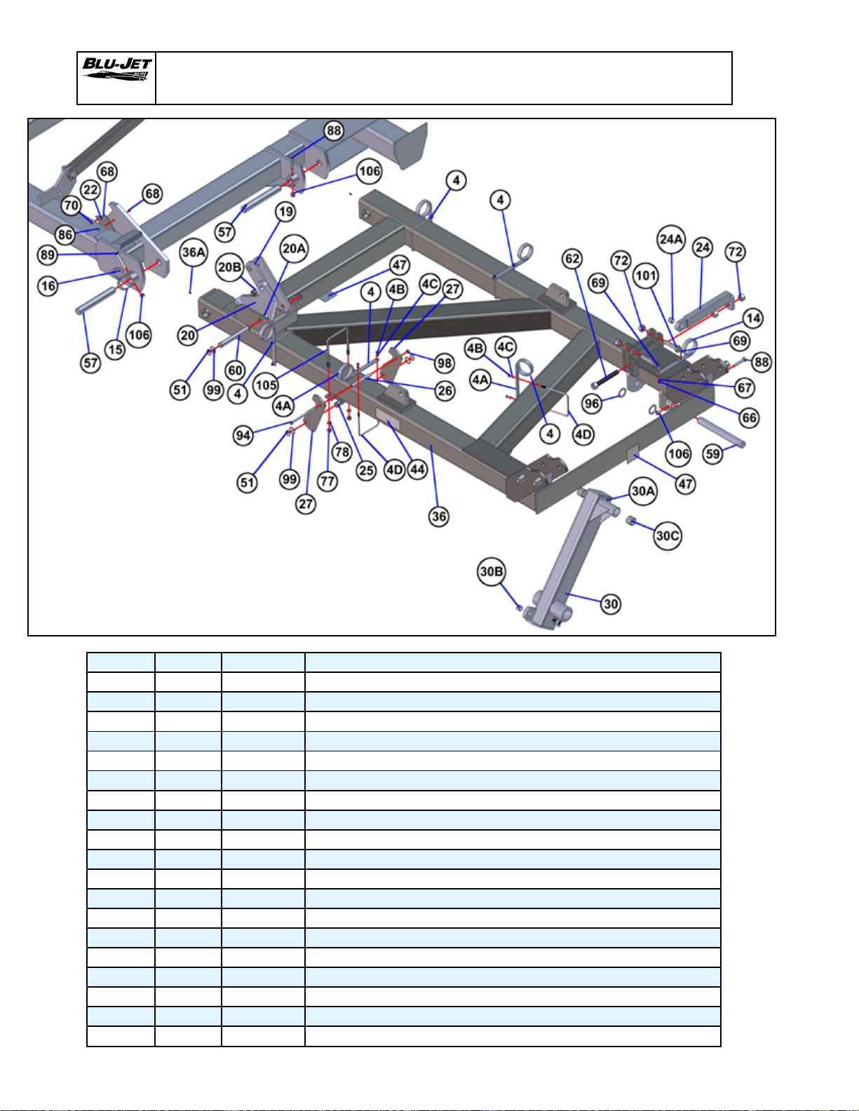
AT6020
Primary Wing Left-hand Area of Bundle 66000103
Tractor Side
BOM ID Qty Item No Description
4 11 AAM2438 HOSE RETAINER ASSEMBLY, CLOSED LOOP, 6X6 TUBE
4A 11 AM4015 HOSE RETAINER, CLOSED LOOP, 6” & 7” MOUNTING
4B 22 BP3001
4C 22 BP3002 WASHER, LOCK, 3/8”, PLATED
4D 11 BP3351 U-BOLT, 3/8”-16 X 6”W X 7”L, PLATED
14 3 AM4015 HOSE RETAINER, CLOSED LOOP, 6” & 7” MOUNTING
15 2 AM4415 HOSE RETAINER, OPEN LOOP
16 2 AM4442 HOSE RETAINER, CLOSED LOOP
19 2 AM4517 WING LOCK
20 2 AM4524 ROCKER, AT6020
20A 4 BP3072 GREASE ZERK, 1/4”-28
20B 2 BP3560 TENSION BUSHING, 1-1/2”X 1-1/4” X 1” OAL
22 2 AM4529 SAFETY LAUNCH TRIP, PRIMARY WING, AT 5000
24 2 AM4564 CYLINDER LUG, SCREW ADJUST
24A 2 BP3516 TENSION BUSHING, 1-1/4” X 1” X 1” OAL
25 2 AM4566 WING LATCH PIVOT, SECONDARY WING
26 2 AM4567 SPACER PIPE, 6-1/4” OAL
27 4 AM4568 SECONDARY WING LOCK PLATE
30 1 AM6163 WHEEL LEG, LH, W/ 2-3/4” SPINDLE LOOP
NUT, HEX, 3/8”-16,
GRADE 2, PLATED
48

AT6020
Primary Wing Left-hand Area of Bundle 66000103
30A 1 BP3213 GREASE ZERK
30B 1 BP3516 TENSION BUSHING, 1-1/4” X 1” X 1” OAL
30C 2 BP3538 TENSION BUSHING, 2” X 1-3/4” X 1-1/2” OAL
36 1 AM6187 WING, PRIMARY, LH, AT6010
36A 2 BP3072 GREASE ZERK, 1/4”-28
44 4 AP2215 DECAL, BLU-JET, 3” X 8”
47 4 AP2234 DECAL, DANGER STAND CLEAR FALLING WING
51 12 AP2711 SNAP RING, 1-1/4” EXTERNAL, HEAVY DUTY
57 4 BM3485 PIN, 1-3/4” X 12-1/8” OAL, W/ 21/32” HOLE, PLATED
59 2 BM3497 PIN, 1-3/4 X 14-3/4 OAL
60 2 BM3544 PIN, 1-1/4 X 9 USEABLE
62 2 BM3555 HEX BOLT, 1”-8 X 7-5/16, FULL THREAD WELDED HEAD
66 12 BP3001
67 12 BP3002 WASHER, LOCK, 3/8”, PLATED
68 9 BP3003
69 6 BP3005
70 2 BP3006
72 14 BP3019
77 16 BP3038 NUT, HEX, 5/8”-11, GRADE 2
78 16 BP3039 WASHER, LOCK, 5/8”, PLATED
86 3 BP3115
88 6 BP3135
89 4 BP3136
94 2 BP3179
96 8 BP3205 MACHINERY BUSHING, 2-1/2” OD X 1-3/4” ID, 10GA, PLATED
98 2 BP3244 NUT, HEX LOCK, 1/2”-13, PLATED
99 12 BP3249 MACHINERY BUSHING, 1-7/8” OD X 1-1/4” ID, 14GA, PLATED
101 6 BP3291
105 2 BP3354 U-BOLT, 5/8”-11 X 4” X 7-3/4”, PLATED
106 10 BP3375 NUT, HEX LOCK, 5/8”-11, NYLOCK
NUT, HEX, 3/8”-16,
NUT, HEX LOCK, 3/8”-16,
HEX CAP SCREW, 3/8”-16 X 1-1/2”,
HEX CAP SCREW, 3/8”-16 X 1”,
NUT, HEX, 1”-8,
HEX CAP SCREW, 3/8”-16 X 2”,
HEX CAP SCREW, 5/8”-11 X 3-1/2”,
HEX CAP SCREW, 5/8”-11 X 4,
HEX CAP SCREW, 1/2”-13 X 8,
HEX CAP SCREW, 1”-8 X 4”,
GRADE 2, PLATED
GRADE 2, PLATED
GRADE 5, PLATED
GRADE 5, PLATED
GRADE 2, PLATED
GRADE 5, PLATED
GRADE 5, PLATED
GRADE 5, PLATED
GRADE 5, PLATED
GRADE 5, PLATED
NOTE:
Complete
bundle:
66000103
quantities
listed
49

AT6020
Secondary Wing Right-hand with Hydraulic Gauge Wheel
Bundle Number:
66000107 (Secondary Wings, Expandable, Right Side)
AAM2800
NOTE:
AAM2800 (With tapered wheel nuts)
and 295/75R22.5 gauge wheel tires.
Do not use AM 4597 with tapered wheel nuts.
AAM2800-1
AM 4597
NOTE:
AAM2800-1 (With ange lock nuts) and
AM4597 hub cap strap are used only with
385/65R22.5 gauge wheel tires. Do not use
AM 4597 with tapered wheel nuts.
50

AT6020
Secondary Wing Right-hand with Hydraulic Gauge Wheel
66000107 Secondary Wings, Expandable, Right Side
BOM ID Qty Item No Description
1 1 AAM2800-1 ASSEMBLY, HUB & SPINDLE, 608 HUB, 2-3/4” X 16” SPINDLE, FLANGE LOCK NUT
2 3 AM4015 HOSE RETAINER, CLOSED LOOP, 6” & 7” MOUNTING
3 1 AM4564 CYLINDER LUG, SCREW ADJUST
4 1 AM4597 HUB CAP STRAP, FOR AAM2800-1 ASSEMBLY
5 1 AM6164 WHEEL LEG, RIGHT HAND, WITH 2-3/4” SPINDLE LOOP
5A 1 BP3213 GREASE ZERK
5B 1 BP3516 TENSION BUSHING, 1-1/4” X 1” X 1” OAL
5C 2 BP3538 TENSION BUSHING, 2” X 1-3/4” X 1-1/2” OAL
5D 3 BP3079 SET SCREW, SQ HEAD, 5/8”-11 X 1-3/4”
5E 3 BP3080 NUT, HEX JAM, 5/8”-11, GRADE 2
6 1 AM6169 WING, SECONDARY, RIGHT HAND, WITH HINGE, EXPANDABLE TO 60’
6A 3 BP3072 GREASE ZERK, 1/4”-28
6B 2 BP3538 TENSION BUSHING, 2” X 1-3/4” X 1-1/2” OAL
7 2 AM6170 ROCKER, 180 DEGREE FOLD
8 2 AM6171 LINKAGE, ROCKER WING FOLD, SINGLE, 11-3/4”
9 2 AM6181 WING REST & LATCH, 180 DEGREE FOLD
10 2 AM6189 LINKAGE, SECONDARY FOLD
10A 2 BP3072 GREASE ZERK, 1/4”-28
11 1 AP2215 DECAL, BLU-JET, 3” X 8”
12 8 AP2711 SNAP RING, 1-1/4 EXTERNAL, HEAVY DUTY
13 1 BM3497 PIN, 1-3/4” X 14-3/4” OAL
14 4 BM3548 PIN, 1-1/4” X 4-3/4”, DOUBLE GROOVED, PLATED
15 1 BM3555 HEX BOLT, 1”-8 X 7-5/16”, FULL THREAD WELDED HEAD
16 2 BM3639 PIN, 1-1/4” X 2-5/8”
17 4 BM3816 PIN, 1-1/4” X 9-13/16” OAL, WITH 13/32” HOLE, PLATED
18 6 BP3001 NUT, HEX, 3/8”-16, GRADE 2, PLATED
19 6 BP3002 WASHER, LOCK, 3/8”, PLATED
20 4 BP3019 NUT, HEX, 1”-8, GRADE 2, PLATED
21 4 BP3038 NUT, HEX, 5/8”-11, GRADE 2
22 4 BP3039 WASHER, LOCK, 5/8”, PLATED
23 4 BP3096 HEX CAP SCREW, 3/8”-16 X 2-1/2”, GRADE 5, PLATED
24 1 BP3135 HEX CAP SCREW, 5/8”-11 X 3-1/2”, GRADE 5, PLATED
25 2 BP3205 MACHINERY BUSHING, 2-1/2” OD X 1-3/4” ID, 10 GAUGE
26 8 BP3249 MACHINERY BUSHING, 1-7/8” OD X 1-1/4” ID, 14 GAUGE
27 2 BP3291 HEX CAP SCREW, 1”-8 X 4”, GRADE 5, PLATED
28 3 BP3351 U-BOLT, 3/8”-16 X 6”W X 7”L
29 2 BP3354 U-BOLT, 5/8”-11 X 6”W X 7-3/4”L, PLATED
30 1 BP3375 NUT, HEX LOCK, 5/8”-11, NYLOCK
31 1 BP3516 TENSION BUSHING, 1-1/4” X 1” X 1” OAL
32 4 CP2660 NUT, HEX LOCK, 3/8”-16, NYLOCK
51

AT6020
Secondary Wing Left-hand with Hydraulic Gauge Wheel
Bundle Number:
66000107 (Secondary Wings, Expandable, Left Side)
AAM2800
NOTE:
AAM2800 (With tapered wheel nuts)
and 295/75R22.5 gauge wheel tires.
Do not use AM 4597 with tapered wheel nuts.
52
AAM2800-1
AM 4597
NOTE:
AAM2800-1 (With ange lock nuts) and
AM4597 hub cap strap are used only with
385/65R22.5 gauge wheel tires. Do not use
AM 4597 with tapered wheel nuts.

AT6020
Secondary Wing Left-hand with Hydraulic Gauge Wheel
66000107 Secondary Wings, Expandable, Left Side
BOM ID Qty Item No Description
1 1 AAM2800-1 ASSEMBLY, HUB & SPINDLE, 608 HUB, 2-3/4” X 16” SPINDLE, FLANGE LOCK NUT
2 3 AM4015 HOSE RETAINER, CLOSED LOOP, 6” & 7” MOUNTING
3 1 AM4564 CYLINDER LUG, SCREW ADJUST
4 1 AM4597 HUB CAP STRAP, FOR AAM2800-1 ASSEMBLY
5 1 AM6164 WHEEL LEG, RIGHT HAND, WITH 2-3/4” SPINDLE LOOP
5A 1 BP3213 GREASE ZERK
5B 1 BP3516 TENSION BUSHING, 1-1/4” X 1” X 1” OAL
5C 2 BP3538 TENSION BUSHING, 2” X 1-3/4” X 1-1/2” OAL
5D 3 BP3079 SET SCREW, SQ HEAD, 5/8”-11 X 1-3/4”
5E 3 BP3080 NUT, HEX JAM, 5/8”-11, GRADE 2
6 1 AM6168 WING, SECONDARY, LEFT HAND, WITH HINGE, EXPANDABLE TO 60’
6A 3 BP3072 GREASE ZERK, 1/4”-28
6B 2 BP3538 TENSION BUSHING, 2” X 1-3/4” X 1-1/2” OAL
7 2 AM6170 ROCKER, 180 DEGREE FOLD
8 2 AM6171 LINKAGE, ROCKER WING FOLD, SINGLE, 11-3/4”
9 2 AM6181 WING REST & LATCH, 180 DEGREE FOLD
10 2 AM6189 LINKAGE, SECONDARY FOLD
10A 2 BP3072 GREASE ZERK, 1/4”-28
11 1 AP2215 DECAL, BLU-JET, 3” X 8”
12 8 AP2711 SNAP RING, 1-1/4” EXTERNAL, HEAVY DUTY
13 1 BM3497 PIN, 1-3/4” X 14-3/4” OAL
14 4 BM3548 PIN, 1-1/4” X 4-3/4”, DOUBLE GROOVED, PLATED
15 1 BM3555 HEX BOLT, 1”-8 X 7-5/16”, FULL THREAD WELDED HEAD
16 2 BM3639 PIN, 1-1/4” X 2-5/8”
17 4 BM3816 PIN, 1-1/4” X 9-13/16” OAL, WITH 13/32” HOLE, PLATED
18 6 BP3001 NUT, HEX, 3/8”-16, GRADE 2, PLATED
19 6 BP3002 WASHER, LOCK, 3/8”, PLATED
20 4 BP3019 NUT, HEX, 1”-8, GRADE 2, PLATED
21 4 BP3038 NUT, HEX, 5/8”-11, GRADE 2
22 4 BP3039 WASHER, LOCK, 5/8”, PLATED
23 4 BP3096 HEX CAP SCREW, 3/8”-16 X 2-1/2”, GRADE 5, PLATED
24 1 BP3135 HEX CAP SCREW, 5/8”-11 X 3-1/2”, GRADE 5, PLATED
25 2 BP3205 MACHINERY BUSHING, 2-1/2” OD X 1-3/4” ID, 10 GAUGE
26 8 BP3249 MACHINERY BUSHING, 1-7/8” OD X 1-1/4” ID, 14 GAUGE
27 2 BP3291 HEX CAP SCREW, 1”-8 X 4”, GRADE 5, PLATED
28 3 BP3351 U-BOLT, 3/8”-16 X 6”W X 7”L
29 2 BP3354 U-BOLT, 5/8”-11 X 6”W X 7-3/4L”, PLATED
30 1 BP3375 NUT, HEX LOCK, 5/8”-11, NYLOCK
31 1 BP3516 TENSION BUSHING, 1-1/4” X 1” X 1” OAL
32 4 CP2660 NUT, HEX LOCK, 3/8”-16, NYLOCK
53

AT6020
Bundle Number:
66000105 (AT6020 Single Wheel)
Right-hand
Dual Wheel Lift Bundle 66000105 (30” Row Spacing)
Right-hand and Left-hand
as viewed from the rear
Left-hand
Right-hand
NOTE:
Valve stem on each wheel is positioned to the inside
of the dual on 30” and 15”.
Left-hand
54

AT6020
Dual Wheel Lift Bundle 66000105 (30” Row Spacing)
66000105 Dual Wheel Lift
BOM ID Qty Item No Description
1 2 AAM2914 WHEEL, 12.4 X 38, 14 PLY 38 X 10 X 8, LEFT HAND ASSEMBLY
1A 2 AP2790 VALVE STEM, METAL
1B 2 AP2867 TIRE, 12.4 X 38, 14 PLY, TRACTION GRIP
1C 2 AP3204 RIM, 38 X 10 X 8, GRAY
2 2 AAM2915 WHEEL, 12.4 X 38, 14 PLY 38 X 10 X 8, RIGHT HAND ASSEMBLY
2A 2 AP2790 VALVE STEM, METAL
2B 2 AP2867 TIRE, 12.4 X 38, 14 PLY, TRACTION GRIP
2C 2 AP3204 RIM, 38 X 10 X 8, GRAY
3 4 AAM2800-1 ASSEMBLY, HUB & SPINDLE, 608 HUB, 2-3/4” X 16” SPINDLE, FLANGE LOCK NUT
4 4 AM4597 HUB CAP STRAP, FOR AAM2800-1 ASSEMBLY
5 1 AM6173 WHEEL LEG, LEFT HAND, DUALS WITH PIVOT
5A 1 BP3072 GREASE ZERK, 1/4”- 28
5B 1 BP3516 TENSION BUSHING, 1-1/4” X 1” X 1” OAL
5C 2 BP3538 TENSION BUSHING, 2” X 1-3/4” X 1-1/2” OAL
6 1 AM6174 WHEEL LEG, RIGHT HAND, DUALS W/ PIVOT
6A 1 BP3072 GREASE ZERK, 1/4”- 28
6B 1 BP3516 TENSION BUSHING, 1-1/4” X 1” X 1” OAL
6C 2 BP3538 TENSION BUSHING, 2” X 1-3/4” X 1-1/2” OAL
7 2 AM6198 DUALS, ROCKER, WITH SPINDLE LOOPS FOR 2-3/4” SPINDLE
7A 2 BP3072 GREASE ZERK, 1/4”- 28
7B 12 BP3079 SET SCREW, SQ HEAD, 5/8”- 11 X 1-3/4”
7C 12 BP3080 NUT, HEX JAM, 5/8”- 11, GRADE 2
8 2 BM3640 PIN, 2” X 12-5/8” OAL
9 2 BP3136 HEX CAP SCREW, 5/8”- 11 X 4”, GRADE 5, PLATED
10 2 BP3375 NUT, HEX LOCK, 5/8”-11, NYLOCK
11 6 BP3599 MACHINERY BUSHING, 3” OD X 2” ID X 10 GAUGE
AP2790
Valve Stem
AAM2914 Wheel
12.4 x 38 14 Ply 38 x 10 x 8
Left-hand
AP2790
Valve Stem
AAM2914 Wheel
12.4 x 38 14 Ply 38 x 10 x 8
Left-hand
AAM2915 Wheel
12.4 x 38 14 Ply 38 x 10 x 8
Right-hand
AP2790
Valve Stem
AP2790
Valve Stem
20” row spacing swap wheel legs from left to right
Outside wheel, valve stems to outside of the dual.
Inside wheels valve stems to inside of the dual.
AAM2915Wheel
12.4 x 38 14 Ply 38 x 10 x 8
Right-hand
55

AT6020
Gauge Wheel With Pin Adjust & 25 x 7.50 x 15 Tire & Rim
Part of Bundle Number: 66000106
Bundle Number 55000100 (Pin Adjust Gauge Wheel)
Tractor side of tool bar
55000100 GAUGE WHEEL, PIN ADJUST 6 X 6 MOUNTING, 25-750-6-6 1 PAIR
BOM ID Qty Item No Description
1 2 AAM2768 WHEEL, 25 X 7.50-15, 4 PLY, 15 X 6 X 6, WHITE
1A 1 AP2001 RIM, 15 X 6 X 6, WHITE
1B 1 AP2017 TIRE, 25 X 7.50- 5,4 PLY, TERRA RIB
1C 1 AP2790 VALVE STEM, METAL
2 2 AM24024 ASSEMBLY, GAUGE WHEEL LEG, PIN ADJUST
3 2 AM24025 BRACKET, PIN ADJUST GAUGE WHEEL MOUNTING
4 4 AP2407 SNAP RING, 1” EXTERNAL, HEAVY DUTY
5 2 BM3650 PIN, 1” X 5-9/16”
6 8 BP3034 NUT, HEX, 3/4”-10, GRADE 2, PLATED
7 8 BP3035 WASHER, LOCK, 3/4”, PLATED
8 2 BP3051 PIN, 1” X 6”, PLATED
9 4 BP3215 MACHINERY BUSHING, 1-1/2” OD X 1” ID, 14 GAUGE, PLATED
10 4 BP3350 U-BOLT, 3/4”-10 X 6”W X 7-11/16”L, PLATED
11 2 BP3511 PIN, COTTER, 3/16” X 1-3/4”
56

AT6020
AT6020, 48’ and 60’ Toolbars
AT6020 48’
AT6020 60’
57

AT6020
AT6020 60’ Hydraulics
PKG000238 Package, Hydraulic, AT6020 Base, Up To 48’
58
Right-hand
From The
Rear

AT6020 60’ Hydraulics
AT6020
BOM ID Qty Item No Description
1 1 PKG00238 PACKAGE, HYD, AT6020 BASE, UPTO 48’
2 2 AM2090 BRACKET, DEPTH COLLAR & LOCKUP STORAGE
3 1 AM6159 BRACKET, MOUNTING, FLOW DIVIDER VALVE
4 2 AM6280 TRANSPORT CYLINDER LOCK, 1-3/4” & 2” ROD, 12”
5 2 BM3520 CLIP PIN, TRANSPORT LOCK
6 6 BM3559 PIN, CLEVIS, 1 X 3 USEABLE, W/ ANTI-ROTATION
7 6 BP3001 NUT, HEX, 3/8”-16, GRD 2, PLTD
8 8 BP3002 WASHER, LOCK, 3/8”, PLTD
9 2 BP3006 HEX CAP SCREW, 3/8”-16 X 1”, GRD 5, PLTD
10 6 BP3028 WASHER, FLAT, 1”, PLTD, STD
11 3 BP3351 U-BOLT, 3/8”-16 X 6W X 7L, PLTD
12 6 BP3511 PIN, COTTER, 3/16 X 1-3/4
13 1 DP4004 TEE, 6MJ-6MJ-6MJ
14 30 DP4086 CABLE TIE 11-3/8” STD
15 17 DP4143 ADAPTER, 10MJIC-8MSAE, 90*
16 1 DP4377 VALVE, REMOTE STROKE CONTROL, PM-SC-10
17 3 DP4379 TEE, RUN, 6FJX-6MJ-6MJ, STL, 6602-6
18 4 DP4383 COUPLER, PIONEER, 8MQBA-8FSAE
19 5 DP4392 ADAPTER, 8MSAE-10MJIC, STRAIGHT, 6400-10-8
20 2 DP4398-1 5” X 36” HYD CYLINDER, W/ 2-3/4” SPACER
21 4 DP4399 REDUCER, 10MSAE-8FSAE, 6410-10-8
22 1 DP4484 REPHASING CYLINDER, 3-1/2 X 12, PMS-AM-2564
23 2 DP4485 REPHASING CYLINDER, 3-3/4 X 12, PMS-AM-2558
24 2 DP4486 REPHASING CYLINDER, 4 X 12, PMS-AM-2552A
25 2 DP4487 REPHASING CYLINDER, 4-1/2” X 12”, PMS-AM2546
26 6 DP4550 TEE, BRANCH, 6FJX-6MJ-6MJ, 6600-6
27 4 DP4551 ADAPTER, 6MJ-8MSAE, W/ RESTRICTOR, 6400R-6-8-093
28 4 DP4579-1 4-1/2” X 20” HYDRAULIC CYLINDER, W/ 7/8” SPACER
29 4 DP4580 ADAPTER, 6MJ-10MSAE, 6400-6-10
30 4 DP4581 ADAPTER, 6MJ-10MSAE, 90°, 6801-6-10
31 1 DP4590 FLOW DIVIDER WITH HOLDING VALVES
32 1 DP6564 PLUG, 8MSAE, HEX, 6408-8
33 1 PKG00207 PACKAGE, HYD, AT6010 ADD-ON, 47-1/2’ TO 60’
33A 4 AAM2111 ADAPTER, 6MJ-8MSAE, 90* W/ 1/8 RESTRICTOR
33B 4 AP2283-1 HOSE RETAINER, 6 X 6, W/PLASTIC CAPS
33C 2 DP4004 TEE, 6MJ-6MJ-6MJ
33D 4 DP4086 CABLE TIE 11-3/8” STD
33E 2 DP4383 COUPLER, PIONEER, 8MQBA-8FSAE
33F 2 DP4492 CYLINDER, HYD, 3 X 20, SIDE PORTED, B300200ABAAA03B
PKG000238 Package, Hydraulic, AT6020 Base, Up To 48’
59

AT6020
AT6020 60’ Hydraulics
PKG00238, Hydraulic Package Base, Up To 48’
BOM ID Qty Item No Description
A 1 DP4496 HOSE, HYD, 1/2 X 114, 10FJX-10FJX
B 1 DP5001 HOSE, HYD, 1/2 X 168, 10FJX-10FJX
C 4 DP5055 HOSE, HYD, 1/4 X 66, 6FJX-6FJX
D 2 DP5184 HOSE, HYD, 1/2 X 192, 10FJX-10FJX
E 3 DP5186 HOSE, HYD, 1/2 X 132, 10FJX-10FJX
F 2 DP5306 HOSE, HYD, 1/4 X 296, 6FJX-6FJX
G 2 DP5307 HOSE, HYD, 1/4 X 272, 6FJX-6FJX
H 1 DP5308 HOSE, HYD, 3/8 X 32, 6FJX-6FJX
I 1 DP5309 HOSE, HYD, 3/8 X 43, 6FJX-6FJX
J 1 DP5310 HOSE, HYD, 3/8 X 77, 6FJX-6FJX
K 2 DP5311 HOSE, HYD, 3/8 X 134, 6FJX-6FJX
L 2 DP5312 HOSE, HYD, 3/8 X 143, 6FJX-6FJX
M 1 DP5316 HOSE, HYD, 1/2 X 353, 10FJX-10FJX
N 1 DP5317 HOSE, HYD, 1/2 X 240, 10FJX-8MSAE
O 4 DP5318 HOSE, HYD, 3/8 X 240, 6FJX-8MSAE
P 1 DP5349 HOSE, HYD, 1/2 X 240, 10FJX-8MSAE
Q 1 DP5230 HOSE, HYD, 1/2 X 42, 10FJX-10FJX
R 1 DP5316 HOSE, HYD, 1/2 X 353, 10FJX-10FJX
60

AT6020
Right-hand
From The
Rear
AT6020 60’ Hydraulics
PKG00238, Hydraulic Package Base, Up To 48’
61

AT6020
AT6020 60’ Hydraulics
PKG00238, Hydraulic Package Base, Up To 48’
Left-hand
From The
Rear
62
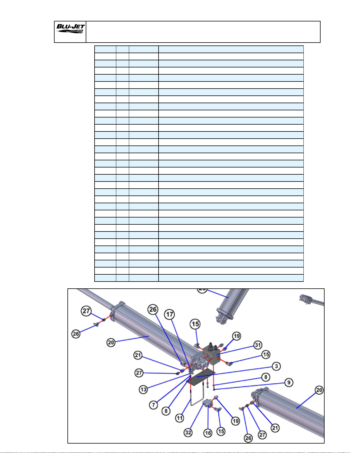
AT6020
AT6020 48’ Hydraulics
BOM ID Qty Item No Description
1 1 PKG00238 PACKAGE, HYD, AT6020 BASE, UPTO 48’
2 2 AM2090 BRACKET, DEPTH COLLAR & LOCKUP STORAGE
3 1 AM6159 BRACKET, MOUNTING, FLOW DIVIDER VALVE
4 2 AM6280 TRANSPORT CYLINDER LOCK, 1-3/4” & 2” ROD, 12”
5 2 BM3520 CLIP PIN, TRANSPORT LOCK
6 6 BM3559 PIN, CLEVIS, 1 X 3 USEABLE, W/ ANTI-ROTATION
7 6 BP3001 NUT, HEX, 3/8”-16, GRD 2, PLTD
8 8 BP3002 WASHER, LOCK, 3/8”, PLTD
9 2 BP3006 HEX CAP SCREW, 3/8”-16 X 1”, GRD 5, PLTD
10 6 BP3028 WASHER, FLAT, 1”, PLTD, STD
11 3 BP3351 U-BOLT, 3/8”-16 X 6W X 7L, PLTD
12 6 BP3511 PIN, COTTER, 3/16 X 1-3/4
13 1 DP4004 TEE, 6MJ-6MJ-6MJ
14 30 DP4086 CABLE TIE 11-3/8” STD
15 17 DP4143 ADAPTER, 10MJIC-8MSAE, 90*
16 1 DP4377 VALVE, REMOTE STROKE CONTROL, PM-SC-10
17 3 DP4379 TEE, RUN, 6FJX-6MJ-6MJ, STL, 6602-6
18 4 DP4383 COUPLER, PIONEER, 8MQBA-8FSAE
19 5 DP4392 ADAPTER, 8MSAE-10MJIC, STRAIGHT, 6400-10-8
20 2 DP4398-1 5” X 36” HYD CYLINDER, W/ 2-3/4” SPACER
21 4 DP4399 REDUCER, 10MSAE-8FSAE, 6410-10-8
22 1 DP4484 REPHASING CYLINDER, 3-1/2 X 12, PMS-AM-2564
23 2 DP4485 REPHASING CYLINDER, 3-3/4 X 12, PMS-AM-2558
24 2 DP4486 REPHASING CYLINDER, 4 X 12, PMS-AM-2552A
25 2 DP4487 REPHASING CYLINDER, 4-1/2” X 12”, PMS-AM2546
26 6 DP4550 TEE, BRANCH, 6FJX-6MJ-6MJ, 6600-6
27 4 DP4551 ADAPTER, 6MJ-8MSAE, W/ RESTRICTOR, 6400R-6-8-093
28 4 DP4579-1 4-1/2” X 20” HYDRAULIC CYLINDER, W/ 7/8” SPACER
29 4 DP4580 ADAPTER, 6MJ-10MSAE, 6400-6-10
30 4 DP4581 ADAPTER, 6MJ-10MSAE, 90°, 6801-6-10
31 1 DP4590 FLOW DIVIDER WITH HOLDING VALVES
32 1 DP6564 PLUG, 8MSAE, HEX, 6408-8
63

AT6020
AT6020 48’ Hydraulics
64

AT6020
AT6020 48’ Hydraulics
Left-hand
From The
Rear
Right-hand
From The
Rear
65

AT6020
AT6020 48’ Hydraulics
BOM ID Qty Item No Description
A 1 DP4496 HOSE, HYD, 1/2 X 114, 10FJX-10FJX
B 1 DP5001 HOSE, HYD, 1/2 X 168, 10FJX-10FJX
C 4 DP5055 HOSE, HYD, 1/4 X 66, 6FJX-6FJX
D 2 DP5184 HOSE, HYD, 1/2 X 192, 10FJX-10FJX
E 3 DP5186 HOSE, HYD, 1/2 X 132, 10FJX-10FJX
H 1 DP5308 HOSE, HYD, 3/8 X 32, 6FJX-6FJX
I 1 DP5309 HOSE, HYD, 3/8 X 43, 6FJX-6FJX
J 1 DP5310 HOSE, HYD, 3/8 X 77, 6FJX-6FJX
K 2 DP5311 HOSE, HYD, 3/8 X 134, 6FJX-6FJX
L 2 DP5312 HOSE, HYD, 3/8 X 143, 6FJX-6FJX
M 1 DP5316 HOSE, HYD, 1/2 X 353, 10FJX-10FJX
N 1 DP5317 HOSE, HYD, 1/2 X 240, 10FJX-8MSAE
O 2 DP5318 HOSE, HYD, 3/8 X 240, 6FJX-8MSAE
P 1 DP5349 HOSE, HYD, 1/2 X 240, 10FJX-8MSAE
Q 1 DP5230 HOSE, HYD, 1/2 X 42, 10FJX-10FJX
R 1 DP5316 HOSE, HYD, 1/2 X 353, 10FJX-10FJX
NOT PICTURED, PART OF 60 FT ASSEMBLY
F 2 DP5306 HOSE, HYD, 1/4 X 296, 6FJX-6FJX
G 2 DP5307 HOSE, HYD, 1/4 X 272, 6FJX-6FJX
66

AT6020
AT6020 48’ Hydraulics
67

AT6020
AT6020 48’ Hydraulics
Right-hand
From The
Rear
68

AT6020
AT6020 48’ Hydraulics
Left-hand
From The
Rear
69

AT6020
Bundle Number:
66000108 Left Side
22
Third Wing Left Side Bundle 66000108
8
70

AT6020
Third Wing Left Side Bundle 66000108
66000108 Third Wing Left Side
BOM ID Qty Item No Description
1 1 AM6166 WING, THIRD, LEFT HAND
2 1 AM3601 LINKAGE, WING FOLD, DOUBLE
2A 1 BP3072 GREASE ZERK, 1/4”-28
3 1 AM3602 LINKAGE, WING FOLD, SINGLE, 11-3/4”
3A 2 BP3072 GREASE ZERK, 1/4”-28
4 1 AM6154 THIRD WING CYLINDER LUG & SADDLE
5 2 BP3205 MACHINERY BUSHING, 2-1/2” OD X 1-3/4” ID, 10 GAUGE
6 1 BM3461 PIN, 1-3/4” X 19-3/4” OAL, WITH 21/32” HOLE, PLATED
7 1 AM6155 WING LATCH MOUNTING, LEFT HAND
8 1 AM6157 WING LATCH HOOK, THIRD WING
9 1 AM6205 WING LATCH, THIRD WING, LEFT HAND
10 1 BM3543 PIN, 1” X 4-5/16” DOUBLE GROOVED, PLATED
11 2 BP3215 MACHINERY BUSHING, 1-1/2” OD X 1” ID, 14 GAUGE, PLATED
12 2 AP2407 SNAP RING, 1” EXTERNAL, HEAVY DUTY
13 1 BP3135 HEX CAP SCREW, 5/8”-11 X 3-1/2”, GRADE 5, PLATED
14 1 BP3375 NUT, HEX LOCK, 5/8”-11, NYLOCK
15 1 BP3143 HEX CAP SCREW, 3/4”-10 X 4”, GRADE 5, PLATED
16 1 BP3027 NUT, HEX LOCK, 3/4”-10, GRADE 2, PLATED
17 3 BP3350 U-BOLT, 3/4”-10 X 6”W X 7-11/16”L, PLATED
18 3 BP3354 U-BOLT, 5/8”-11 X 4” X 7-3/4”, PLATED
19 6 BP3034 NUT, HEX, 3/4”-10, GRADE 2, PLATED
20 6 BP3038 NUT, HEX, 5/8”-11, GRADE 2
21 6 BP3035 WASHER, LOCK, 3/4”, PLATED
22 6 BP3039 WASHER, LOCK, 5/8”, PLATED
23 1 BM3563 PIN, 1” X 7” OAL, WITH 13/32” HOLE
24 1 BP3115 HEX CAP SCREW, 3/8”-16 X 2”, GRADE 5, PLATED
25 1 CP2660 NUT, HEX LOCK, 3/8”-16, NYLOCK
26 1 66000102L SWING ADJUST GAUGE WHEEL, LEFT SIDE
26A 1 AM6186 BRACKET, MOUNTING, 6”, SWING ADJUST GAUGE WHEEL
26B 1 AM7581 WHEEL LEG, GAUGE WHEEL
26C 1 BP3079 SET SCREW, SQ HEAD, 5/8”-11 X 1-3/4”
26D 1 BP3080 NUT, HEX JAM, 5/8”-11, GRADE 2
26E 1 BP3211 NUT, HEX, 5/8”-11, GRADE 2
26F 1 AAM2707 ASSEMBLY, HUB & SPINDLE, 511 HUB, 1-3/4” X 13”
26G 1 AAM2781 WHEEL, 20.5 X 8.0-10, 10 X 6, WHITE
26H 1 BM3547 PIN, 1-1/4” X 5-3/4”
26I 1 BP3051 PIN, 1” X 6”, PLATED
26J 2 BP3249 MACHINERY BUSHING, 1-7/8” OD X 1-1/4” ID, 14 GAUGE
26K 2 AP2711 SNAP RING, 1-1/4” EXTERNAL, HEAVY DUTY
26L 1 BP3350 U-BOLT, 3/4”-10 X 6”W X 7-11/16”L, PLATED
26M 2 BP3035 WASHER, LOCK, 3/4”, PLATED
26N 2 BP3034 NUT, HEX, 3/4”-10, GRADE 2, PLATED
26O 1 BP3500 PIN, HAIR CLIP, 3/16”
27 1 AP2215 DECAL, BLU-JET, 3” X 8”
28 1 BM3816 PIN, 1-1/4” X 9-13/16” OAL, WITH 13/32” HOLE, PLATED
29 1 BP3096 HEX CAP SCREW, 3/8”-16 X 2-1/2”, GRADE 5, PLATED
30 1 CP2660 NUT, HEX LOCK, 3/8”-16, NYLOCK
71

AT6020
Bundle Number:
66000108 Right Side
Third Wing Right Side Bundle 66000108
2a
2a
72

AT6020
Third Wing Right Side Bundle 66000108
66000108 Right Wing Left Side
BOM ID Qty Item No Description
1 1 AM6167 WING, THIRD, RIGHT HAND
2 1 AM3601 LINKAGE, WING FOLD, DOUBLE
2A 1 BP3072 GREASE ZERK, 1/4”-28
3 1 AM3602 LINKAGE, WING FOLD, SINGLE, 11-3/4”
3A 2 BP3072 GREASE ZERK, 1/4”-28
4 1 AM6154 THIRD WING CYLINDER LUG & SADDLE
5 2 BP3205 MACHINERY BUSHING, 2-1/2” OD X 1-3/4” ID, 10 GAUGE
6 1 BM3461 PIN, 1-3/4” X 19-3/4” OAL WITH 21/32” HOLE, PLATED
7 1 AM6156 WING LATCH MOUNTING, RIGHT HAND
8 1 AM6157 WING LATCH HOOK, THIRD WING
9 1 AM6206 WING LATCH, THIRD WING, RIGHT HANK
10 1 BM3543 PIN, 1” X 4-5/16”, DOUBLE GROOVED, PLATED
11 2 BP3215 MACHINERY BUSHING, 1-1/2” OD X 1” ID, 14 GAUGE, PLATED
12 2 AP2407 SNAP RING, 1” EXTERNAL, HEAVY DUTY
13 1 BP3135 HEX CAP SCREW, 5/8”-11 X 3-1/2”, GRADE 5, PLATED
14 1 BP3375 NUT, HEX LOCK, 5/8”-11, NYLOCK
15 1 BP3143 HEX CAP SCREW, 3/4”-10 X 4”, GRADE 5, PLATED
16 1 BP3027 NUT, HEX LOCK, 3/4”-10, GRADE 2, PLATED
17 3 BP3350 U-BOLT, 3/4”-10 X 6”W X 7-11/16”L, PLATED
18 3 BP3354 U-BOLT, 5/8”-11 X 4” X 7-3/4”, PLATED
19 6 BP3034 NUT, HEX, 3/4”-10, GRADE 2, PLATED
20 6 BP3038 NUT, HEX, 5/8”-11, GRADE 2
21 6 BP3035 WASHER, LOCK, 3/4”, PLATED
22 6 BP3039 WASHER, LOCK, 5/8”, PLATED
23 1 BM3563 PIN, 1” X 7” OAL, WITH 13/32” HOLE
24 1 BP3115 HEX CAP SCREW, 3/8”-16 X 2”, GRADE 5, PLATED
25 1 CP2660 NUT, HEX LOCK, 3/8”-16, NYLOCK
26 1 66000102R SWING ADJUST GAUGE WHEEL, RIGHT SIDE
26A 1 AM6186 BRACKET, MOUNTING, 6”, SWING ADJUST GAUGE WHEEL
26B 1 AM7581 WHEEL LEG, GAUGE WHEEL
26C 1 BP3079 SET SCREW, SQUARE HEAD, 5/8”-11 X 1-3/4”
26D 1 BP3080 NUT, HEX JAM, 5/8”-11, GRADE 2
26E 1 BP3211 NUT, HEX, 5/8”-11, GRADE 2
26F 1 AAM2707 ASSEMBLY, HUB & SPINDLE, 511 HUB, 1-3/4” X 13”
26G 1 AAM2781 WHEEL, 20.5 X 8.0-10, 10 X 6, WHITE
26H 1 BM3547 PIN, 1-1/4” X 5-3/4”
26I 1 BP3051 PIN, 1” X 6”, PLATED
26J 2 BP3249 MACHINERY BUSHING, 1-7/8” OD X 1-1/4” ID, 14 GAUGE
26K 2 AP2711 SNAP RING, 1-1/4 EXTERNAL, HEAVY DUTY
26L 1 BP3350 U-BOLT, 3/4”-10 X 6”W X 7-11/16”L, PLATED
26M 2 BP3035 WASHER, LOCK, 3/4”, PLATED
26N 2 BP3034 NUT, HEX, 3/4”-10, GRADE 2, PLATED
26O 1 BP3500 PIN, HAIR CLIP, 3/16”
27 1 AP2215 DECAL, BLU-JET, 3” X 8”
28 1 BM3816 PIN, 1-1/4” X 9-13/16” OAL, WITH 13/32” HOLE, PLATED
29 1 BP3096 HEX CAP SCREW, 3/8”-16 X 2-1/2”, GRADE 5, PLATED
30 1 CP2660 NUT, HEX LOCK, 3/8”-16, NYLOCK
73

AT6020
Stagger Brackets Offset 6” x 6” Mounting
BOM ID Qty Item No Description
1 1 AAM2141 BRACKET, OFFSET STAGGER, 22 X 8, 6 X 6,
2 1 AM4510 BRACKET, OFFSET STAGGER, 22 X 8
3 2 BP3350 U-BOLT, 3/4”-10 X 6”W X 7-11/16”L, PLATED
4 4 BP3034 NUT, HEX, 3/4”-10, GRADE 2, PLATED
5 4 BP3035 WASHER, LOCK, 3/4”, PLATED
W/ HARDWARE
BOM ID Qty Item No Description
1 1 AAM2123 BRACKET, OFFSET STAGGER, 22 X 20, 6 X 6,
2 1 AM4545 BRACKET, OFFSET STAGGER, 22 X 20
3 4 BP3034 NUT, HEX, 3/4”-10, GRADE 2, PLATED
4 4 BP3035 WASHER, LOCK, 3/4”, PLATED
5 2 BP3350 U-BOLT, 3/4”-10 X 6”W X 7-11/16”L, PLATED
W/ HARDWARE
BOM ID Qty Item No Description
1 1 AAM2130 BRACKET, EXTENSION, 26”, 6 X 6, W/HARDWARE
2 1 AM4542 BRACKET, EXTENSION, 26”, 6” MTG, W/ ANTI-ROTATION
3 4 BP3034 NUT, HEX, 3/4”-10, GRADE 2, PLATED
4 4 BP3035 WASHER, LOCK, 3/4”, PLATED
5 2 BP3352 U-BOLT, 3/4”-10 X 6”W X 5-11/16”L, PLATED
NOTE: Consult row spacing
diagram for placement of offset
stagger brackets.
74
BOM ID Qty Item No Description
1 1 AAM2128 BRACKET, EXTENSION, 14”, 6 x 6, W/HARDWARE
2 1 AM4543 BRACKET, EXTENSION, 14”, 6” MTG, W/ANTI-ROTATION
3 4 BP3034 NUT, HEX, 3/4”-10, GRADE 2, PLATED
4 4 BP3035 WASHER, LOCK, 3/4”, PLATED
5 2 BP3352 U-BOLT, 3/4”-10 X 6”W X 5-11/16”L, PLATED

AT6020
Stagger Brackets Offset 6” x 6” Mounting
BOM ID Qty Item No Description
1 1 AAM2122 BRACKET, OFFSET STAGGER, 33 X 20, 6 X 6,
2 1 AM4509 BRACKET, OFFSET STAGGER, 33X20
3 4 BP3034 NUT, HEX, 3/4”-10 GRADE 2, PLATED
4 4 BP3035 WASHER, LOCK, 3/4”, PLATED
5 2 BP3350 U-BOLT, 3/4”-10 X 6”W X 7-11/16”L, PLATED
W/HARDWARE
NOTE: Consult row spacing
diagram for placement of offset
stagger brackets.
BOM ID Qty Item No Description
1 1 AAM2129 BRACKET, EXTENSION, 20”, 6 x 6, W/HARDWARE
2 1 AM6162 BRACKET, EXTENSION, 20”, 6” MTG, W/ ANTI-ROTATION
3 4 BP3034 NUT, HEX, 3/4”-10, GRADE 2, PLATED
4 4 BP3035 WASHER, LOCK, 3/4”, PLATED
5 2 BP3352 U-BOLT, 3/4”-10 X 6”W X 5-11/16”L, PLATED
BOM ID Qty Item No Description
1 1 AAM2125 BRACKET, OFFSET STAGGER, 40 X 48 DOUBLE, 6 X 6,
W/HARDWARE
2 1 AM6160 TUBE, 4’, 6” X 6”, CAPPED
3 1 AM6161 BRACKET, EXTENSION, 35”, DOUBLE MTG, 6 X 6
4 16 BP3034 NUT, HEX, 3/4”-10, GRD 2, PLTD
5 16 BP3035 WASHER, LOCK, 3/4”, PLTD
6 8 BP3350 U-BOLT, 3/4”-10 X 6”W X 7-11/16”L, PLTD
75

AT6020
AAM2136 Offset Stagger Bracket
BOM ID Qty Item No Description
1 1 AAM2136 BRACKET, OFFSET STAGGER EXTENSION, 48”, 6 X 6 TUBE
2 1 AM6185 BACKING PLATE, NURSE TANK HITCH MTG, 6” MOUNT
3 1 AM6192 EXTENSION, STAGGER, 48”, 6” MTG
4 4 BP3019 NUT, HEX, 1”-8, GRD 2, PLTD
5 4 BP3020 WASHER, LOCK, 1, PLTD
6 4 BP3421 HEX CAP SCREW, 1”-8 X 9, GRD 5, PLTD
76

AT6020
Super 1200 Flex Coulter and Shank Parts
AP2707, HUB ASSEMBLY, 4 BOLT
BOM ID Qty Item No Description
1 1 AP2707 HUB ASSEMBLY, 4 BOLT
2 1 AP2703 HUB CAP, 1610
3 1 AP2706-1 HUB W/ CUPS, 4 BOLT, 5” BC, 3.62” PILOT, W/ZERK HOLE
3A 1 AP2075 BEARING CUP, LM 11910
3B 1 AP2524 BEARING CUP, LM 67010
4 1 AP2747 GREASE SEAL, 15235TB
5 1 AP2023 BEARING CONE, LM 67048
6 1 AP2024 BEARING CONE, LM 11949
7 4 AP2702 HEX CAP SCREW, 1/2”-20 X 1”, GRADE 5, PLATED
8 1 BP3072 GREASE ZERK, 1/4”-28
AM2799, ASSEMBLY, COULTER ARM WITH HUB & KNEE CASTING, HD
BOM ID Qty Item No Description
1 1 AM2799 ASSEMBLY, COULTER ARM WITH HUB & KNEE CASTING, HD
2 1 AM2743 CASTING, COULTER KNEE, HD, MACHINED WITH BUSHINGS
2A 2 AP2274 BUSHING, 1-17/32” OD X 1-3/8” ID” X 1” OAL
2B 1 AP2477-1 CASTING, COULTER KNEE, MACHINED
3 1 AM2796 SPRING CAP & GUIDE, HD COULTER
4 1 AM2797 COULTER ARM, HD
4A 1 AP2216 DECAL, BLU-JET, SMALL, 1-1/2” X 4”
5 1 AP2029 PIN, COTTER, 5/32” X 1-1/2”
6 1 AP2704 NUT, SPINDLE, 3/4”-16
7 1 AP2705 WASHER, SPINDLE, 1-1/2” X 13/16” X .134”
8 1 AP2881D SPRING, 2.472” OD X 5.875” OAL, .468 WIRE DIAMETER
9 1 BP3072 GREASE ZERK, 1/4”-28
10 1 BP3404 MACHINERY BUSHING, 2-1/8” OD X 1-3/8” ID X 10 GAUGE, PLATED
11 1 BP3405 SNAP RING, 1-3/8” EXTERNAL, 5160-137
AAM2728 COULTER, SUPER 1200, 16, 1 ROW
BOM ID Qty Item No Description
1 1 AAM2728 COULTER, SUPER 1200, 16, 1R
2 1 AM2735 COULTER SHANK, 16”
3 1 AM2799 ASSEMBLY, COULTER ARM W/ HUB & KNEE CASTING, HD
4 1 BP3162 PIN, ROLL, 3/8” X 2”, PLATED
5 1 BP3205 MACHINERY BUSHING, 2-1/2” OD X 1-3/4” ID, 10GA, PLATED
6 1 BP3519 PIN, ROLL, 3/8” X 2-1/2”, PLAIN
7 1 BP3534 PIN, ROLL, 7/32” X 2-1/2”, PLAIN
77

AT6020
PKG00234 Nurse Tank Hitch Assembly Parts
78
BOM ID Qty Item No Description
1 1 PKG00234 NURSE TANK HITCH ASSEMBLY, AT6020
2 1 AAM2931 ASSEMBLY, NURSE TANK HITCH, AUTO-LOK, W/O PIN
3 2 AM6220 BRACKET, HITCH MOUNTING, AT6010 NURSE TANK
4 1 AM6273 BRACKET, NURSE TANK HITCH MOUNTING, LOW
5 1 AM6278 LINKAGE, NURSE TANK HITCH, 12-3/4”
6 4 AP2711 SNAP RING, 1-1/4” EXTERNAL, HEAVY DUTY
7 1 BM3544 PIN, 1-1/4” X 9” USEABLE
8 1 BM3547 PIN, 1-1/4” X 5-3/4” USEABLE
9 2 BM3632 PIN, CATEGORY IV, UPPER LINK
10 8 BP3034 NUT, HEX, 3/4”-10, GRADE 2, PLATED
11 8 BP3035 WASHER, LOCK, 3/4”, PLATED
12 2 BP3135 HEX CAP SCREW, 5/8”-11 X 3-1/2”, GRADE 5, PLATED
13 12 BP3140 HEX CAP SCREW, 3/4”-10 X 2-1/2, GRADE 5, PLATED
14 4 BP3208 U-BOLT, 3/4”-10 X 6”W X 5-11/16”L, PLATED
15 4 BP3249 MACHINERY BUSHING, 1-7/8” OD X 1-1/4” ID, 14GA, PLATED
16 2 BP3375 NUT, HEX LOCK, 5/8”-11, NYLOCK
17 12 BP3442 NUT, HEX LOCK, 3/4”-10, TOP LOCK, GRADE C, PLATED

AT6020
PKG00247 Nurse Tank Hitch Assembly,
Low Mounting Parts
BOM ID Qty Item No Description
1 1 PKG00247 NURSE TANK HITCH ASSEMBLY, AT6, LOW MOUNTING
2 1 AAM2931 ASSEMBLY, NURSE TANK HITCH, AUTO-LOK, W/O PIN
3 2 AM6234 BRACKET, LOW HITCH MOUNTING, AT6020 NURSE TANK
4 1 AM6273 BRACKET, NURSE TANK HITCH MOUNTING, LOW
5 1 AM6278 LINKAGE, NURSE TANK HITCH, 12-3/4”
6 4 AP2711 SNAP RING, 1-1/4” EXTERNAL, HEAVY DUTY
7 1 BM3544 PIN, 1-1/4” X 9” USEABLE
8 1 BM3547 PIN, 1-1/4” X 5-3/4” USEABLE
9 2 BM3632 PIN, CATEGORY IV, UPPER LINK
10 8 BP3034 NUT, HEX, 3/4”-10, GRADE 2, PLATED
11 8 BP3035 WASHER, LOCK, 3/4”, PLATED
12 2 BP3135 HEX CAP SCREW, 5/8”-11 X 3-1/2”, GRADE 5, PLATED
13 12 BP3140 HEX CAP SCREW, 3/4”-10 X 2-1/2”, GRADE 5, PLATED
14 4 BP3208 U-BOLT, 3/4”-10 X 6”W X 5-11/16”L, PLATED
15 4 BP3249 MACHINERY BUSHING, 1-7/8” OD X 1-1/4” ID, 14GA, PLATED
16 2 BP3375 NUT, HEX LOCK, 5/8”-11, NYLOCK
17 12 BP3442 NUT, HEX LOCK, 3/4”-10, TOP LOCK, GRADE C, PLATED
79

AT6020
Auto-Lok Nurse Tank Hitch AAM2931 Parts
80

Auto-Lok Nurse Tank Hitch AAM2931 Parts
AT6020
BOM ID Qty Item No Description
1 1 AAM2931 ASSEMBLY, NURSE TANK HITCH, AUTO-LOK, W/O PIN
2 1 AM4533 HITCH, SWING SLIDE INSERT, STANDARD
3 1 AM4534 FLIPPER HITCH, STANDARD, NURSE TANK HITCH
4 1 AM4539 SAFETY LATCH
5 1 AM4540 BACKING PLATE, SAFETY CHAIN LOOP, STD NURSE TANK HITCH
6 1 AM6230 BRACKET, SAFETY CHAIN ATTACHMENT
7 1 AM6272 HITCH, NURSE TANK, MAIN FRAME
7A 1 AM4536 INSERT LATCH, NURSE TANK HITCH
7B 2 AP2407 SNAP RING, 1” EXTERNAL, HEAVY DUTY
7C 1 BM3551 PIN, 1” X 15-1/8” USEABLE
7D 2 BP3215 MACHINERY BUSHING, 1-1/2” OD X 1” ID, 14GA, PLATED
8 2 AP2585 DECAL, HITCH CAPACITY, 25000 LB
9 1 AP2711 SNAP RING, 1-1/4” EXTERNAL, HEAVY DUTY
10 1 BM3549 PIN, 1-1/4” X 5-5/16” USEABLE, GROOVED W/ ANTI-ROTATION PIN
11 1 BP3003 NUT, HEX LOCK, 3/8”-16, GRADE 2, PLATED
12 1 BP3006 HEX CAP SCREW, 3/8”-16 X 1”, GRADE 5, PLATED
13 1 BP3072 GREASE ZERK, 1/4”-28
14 1 BP3192 MACHINERY BUSHING, 1-7/8” OD X 1-1/4” ID X 10GA, PLATED
15 2 BP3257 GREASE ZERK, 1/4”-28, 65°
16 1 BP3442 NUT, HEX LOCK, 3/4”-10, TOP LOCK, GRADE C, PLATED
17 1 BP3449 HEX CAP SCREW, 3/4”-10 X 6”, GRADE 8, PLATED
81

AT6020
Blades
Coulter Blade
Fluted Blade 20”
AP2701
SealPro (Disc Sealer) Blade Options
AM2479
17” Notched Blade
AM2473
18” hoe wheel
AP2728
17” wavy
82

AT6020
SealPro (AAM2855) Disc Sealer
1” x 2” Shank Parts
AAM2855 SEALER II, 1” X 2” SHANK, 1 ROW
BOM ID Qty Item No Description
1 2 AM2481 ASSEMBLY, SEALER HANGER WITH BLADE MOUNTING
2 1 AM2485 ASSEMBLY, SEALER MOUNTING BRACKET
2A 1 AM2484 BRACKET, SEALER MOUNTING
2B 1 BM3643 PIN, 1-1/4” X 12-1/2” OAL, SEALER SHAFT
2C 2 BP3003 NUT, HEX LOCK, 3/8”-16, GRADE 2, PLATED
2D 2 BP3096 HEX CAP SCREW, 3/8”-16 X 2-1/2”, GRADE 5, PLATED
3 1 AM2486 SEALER ARM, LEFT HAND
3A 2 AP3115 BUSHING, SELF-LUBRICATED 1-1/4” X 1-1/4” LONG
4 1 AM2487 SEALER ARM, RIGHT HAND
4A 2 AP3115 BUSHING, SELF-LUBRICATED 1-1/4” X 1-1/4” LONG
5 4 BP3041 HEX CAP SCREW, 1/2”-13 X 2”, GRADE 5, PLATED
6 16 BP3042 NUT, HEX, 1/2”-13, GRADE 2, PLATED
7 16 BP3043 WASHER, LOCK, 1/2”, PLATED
8 8 BP3050 WASHER, FLAT, 1/2”, PLATED
9 8 BP3125 HEX CAP SCREW, 1/2”-13 X 1”, GRADE 5, PLATED
10 2 BP3162 PIN, ROLL, 3/8” X 2”, PLATED
11 2 BP3249 MACHINERY BUSHING, 1-7/8” OD X 1-1/4” ID, 14 GAUGE
12 2 BP3313 U-BOLT, 1/2”-13 X 2”W X 2-3/4”L, PLATED
Notched Blade Optional
83

AT6020
SealPro II (AAM2856) Disc Sealer
1-1/4” EdgeBent Shank
84
AAM2856 SEALER II, 1-1/4” EDGEBENT SHANK, 1 ROW
BOM ID Qty Item No Description
1 2 AM2481 ASSEMBLY, SEALER HANGER WITH BLADE MOUNTING
2 1 AM2485 ASSEMBLY, SEALER MOUNTING BRACKET
2A 1 AM2484 BRACKET, SEALER MOUNTING
2B 1 BM3643 PIN, 1-1/4” X 12-1/2” OAL, SEALER SHAFT
2C 2 BP3003 NUT, HEX LOCK, 3/8”-16, GRADE 2, PLATED
2D 2 BP3096 HEX CAP SCREW, 3/8”-16 X 2-1/2”, GRADE 5, PLATED
3 1 AM2486 SEALER ARM, LEFT HAND
3A 2 AP3115 BUSHING, SELF-LUBRICATED 1-1/4” X 1-1/4” LONG
4 1 AM2487 SEALER ARM, RIGHT HAND
4A 2 AP3115 BUSHING, SELF-LUBRICATED 1-1/4” X 1-1/4” LONG
5 4 BP3041 HEX CAP SCREW, 1/2”-13 X 2”, GRADE 5, PLATED
6 16 BP3042 NUT, HEX, 1/2”-13, GRADE 2, PLATED
7 16 BP3043 WASHER, LOCK, 1/2”, PLATED
8 8 BP3050 WASHER, FLAT, 1/2”, PLATED
9 8 BP3125 HEX CAP SCREW, 1/2”-13 X 1”, GRADE 5, PLATED
10 2 BP3162 PIN, ROLL, 3/8” X 2”, PLATED
11 2 BP3249 MACHINERY BUSHING, 1-7/8” OD X 1-1/4” ID, 14 GAUGE
12 2 BP3314 U-BOLT, 1/2”-13 X 1-1/4”W X 3-3/4”L, PLATED
Notched Blade Optional

AT6020
SealPro II (AM2481) Assembly,
Sealer Hanger With Blade Mounting
AAM2481 ASSEMBLY, SEALER HANGER WITH BLADE MOUNTING
BOM ID Qty Item No Description
1 1 AM2482 HUB CAP RETAINER
2 1 AP2216 DECAL, BLU-JET, SMALL, 1-1/2” X 4”
3 2 AP2377 BEARING CONE, L44649
4 1 AP2380 HUB CAP
5 1 AP2426 PIN, COTTER, 5/32” X 1-3/4”
6 1 AP2811 NUT, SPINDLE, 1”-14
7 1 AP4209 GREASE SEAL, DOUBLE LIP
8 1 BP3042 NUT, HEX, 1/2”-13, GRADE 2, PLATED
9 1 BP3043 WASHER, LOCK, 1/2”, PLATED
10 1 BP3072 GREASE ZERK, 1/4”-28
11 1 BP3126 HEX CAP SCREW, 1/2”-13 X 1-1/2”, GRADE 5, PLATED
12 1 BP3739 MACHINERY BUSHING, 1-1/2” OD X 1” ID X 14 GAUGE
13 1 EM3245 BLADE MOUNTING
14 1 EM3246 SEALER HANGER
14A 2 AP2376 BEARING CUP, L44610
85

AT6020
SealPro SKF (AAM2892) Disc Sealer
1 X 2” Shank
BOM ID Qty Item No Description
1 1 AAM2892 SEALPRO SKF, 1X2 SHANK, 1 ROW
2 1 AM2485 ASSEMBLY, SEALER MOUNTING BRACKET
2A 1 AM2484 BRACKET, SEALER MOUNTING
2B 1 BM3643 PIN, 1-1/4” X 12-1/2” OAL, SEALER SHAFT
2C 2 BP3003 NUT, HEX LOCK, 3/8”-16, GRADE 2, PLATED
2D 2 BP3096 HEX CAP SCREW, 3/8”-16 X 2-1/2”, GRADE 5, PLATED
3 2 AM2745 SEALER HANGER MOUNT, FOR SKF HUB
4 2 AM2747 SPACER, SEALPRO BLADE
5 2 AM2748 WASHER, 1-1/2” OD X 25/32” ID X 1/4”
6 2 AM2749 BOLT, MOUNTING, SEALPRO HUB
7 1 AM2750 SEALER ARM, LH, GREASEABLE, 2 POSITION
7A 1 BP3072 GREASE ZERK, 1/4”-28
8 1 AM2751 SEALER ARM, RH, GREASEABLE, 2 POSITION
8A 1 BP3072 GREASE ZERK, 1/4”-28
9 2 AP2216 DECAL, BLU-JET, SMALL, 1-1/2” X 4”
10 2 AP4581 BEARING UNIT, ADH 7546
11 4 BP3041 HEX CAP SCREW, 1/2”-13 X 2”, GRADE 5, PLATED
12 8 BP3042 NUT, HEX, 1/2”-13, GRADE 2, PLATED
13 8 BP3043 WASHER, LOCK, 1/2”,PLATED
14 6 BP3050 WASHER, FLAT, 1/2”, PLATED
15 12 BP3150 HEX CAP SCREW, 1/4”-20 X 1”, GRADE 5, PLATED
16 2 BP3162 PIN, ROLL, 3/8” X 2”, PLATED
17 2 BP3249 MACHINERY BUSHING, 1-7/8” OD X 1-1/4” ID, 14GA, PLATED
18 2 BP3313 U-BOLT, 1/2”-13 X 2”W X 2-3/4”L, PLATED
19 12 BP3367 NUT, HEX FLANGE, 1/4”-20, SERRATED, GRADE 2, PLATED
20 2 BP3375 NUT, HEX LOCK, 5/8”-11, NYLOCK
86

AT6020
SealPro SKF (AAM2893) Disc Sealer
1-1/4” Edgebent Shank
BOM ID Qty Item No Description
1 1 AAM2893 SEALPRO SKF, 1-1/4 EDGEBENT, 1 ROW
2 1 AM2485 ASSEMBLY, SEALER MTG BRACKET
2A 1 AM2484 BRACKET, SEALER MOUNTING
2B 1 BM3643 PIN, 1-1/4” X 12-1/2” OAL, SEALER SHAFT
2C 2 BP3003 NUT, HEX LOCK, 3/8”-16, GRD 2, PLTD
2D 2 BP3096 HEX CAP SCREW, 3/8”-16 X 2-1/2”, GRD 5, PLTD
3 2 AM2745 SEALER HANGER MOUNT, FOR SKF HUB
4 2 AM2747 SPACER, SEALPRO BLADE
5 2 AM2748 WASHER, 1-1/2” OD X 25/32” ID X 1/4”
6 2 AM2749 BOLT, MOUNTING, SEALPRO HUB
7 1 AM2750 SEALER ARM, LH, GREASEABLE, 2 POSITION
7A 1 BP3072 GREASE ZERK, 1/4”-28
8 1 AM2751 SEALER ARM, RH, GREASEABLE, 2 POSITION
8A 1 BP3072 GREASE ZERK, 1/4”-28
9 2 AP2216 DECAL, BLU-JET, SMALL, 1-1/2” X 4”
10 2 AP4581 BEARING UNIT, ADH 7546
11 4 BP3041 HEX CAP SCREW, 1/2”-13 X 2”, GRD 5, PLTD
12 8 BP3042 NUT, HEX, 1/2”-13, GRD 2, PLTD
13 8 BP3043 WASHER, LOCK, 1/2”, PLTD
14 6 BP3050 WASHER, FLAT, 1/2”, PLTD
15 12 BP3150 HEX CAP SCREW, 1/4”-20 X 1”, GRD 5, PLTD
16 2 BP3162 PIN, ROLL, 3/8” X 2”, PLTD
17 2 BP3249 MACHINERY BUSHING, 1-7/8” OD X 1-1/4” ID, 14GA, PLTD
18 2 BP3314 U-BOLT, 1/2”-13 X 1-1/4W X 3-3/4L, PLTD
19 12 BP3367 NUT, HEX FLANGE, 1/4”-20, SERRATED, GRADE 2, PLATED
20 2 BP3375 NUT, HEX LOCK, 5/8”-11, NYLOCK
87

AT6020
SealPro II (AAM2857) Assembly,
Optional Sealer II Spring Add-on Kit 1 Row
88
AAM2857 OPTIONAL SEALER II SPRING ADD-ON KIT 1 ROW
BOM ID Qty Item No Description
1 2 AM2488 CLEVIS, SEALER SPRING, UPPER
2 2 AM2489 CLEVIS, SEALER SPRING, LOWER
3 2 AM2490 TUBE, UPPER SPRING
4 2 AM2491 BUSHING, SPRING COLLAR
5 2 AM2492 TUBE, SPRING GUIDE
6 2 AP2997W SPRING, 1.75” OD X 1.313” ID X 6.00” OAL
7 2 AP3116 TUBE PLUG
8 4 BP3042 NUT, HEX, 1/2”-13, GRADE 2, PLATED
9 4 BP3043 WASHER, LOCK, 1/2”, PLATED
10 8 BP3050 WASHER, FLAT, 1/2”, PLATED
11 4 BP3126 HEX CAP SCREW, 1/2”-13 X 1-1/2”, GRADE 5, PLATED
12 2 BP3129 HEX CAP SCREW, 1/2”-13 X 3”, GRADE 5, PLATED
13 2 BP3130 HEX CAP SCREW, 1/2”-13 X 3-1/2”, GRADE 5, PLATED
14 4 BP3244 NUT, HEX LOCK, 1/2”-13, PLATED

AT6020
SealPro II (AAM2857) Assembly,
Optional Sealer II Spring Add-on Kit 1 Row
Mounting
Spring
Add-on Kit
111
2
111
9
111
8
NOTE:
(2) (AM2489)
sealer spring
clevis must
be mounted
with the hole
to the front
1. Mount (2) (AM2489) sealer
spring clevis lower to arm
with clevis hole to the front.
Install (11) (BP3126) 1/2” x
1-1/2” grade 5, hex cap screw.
Secure with (9) (BP 3043) 1/2”
lock washer and (8) (BP 3042)
1/2” hex nut.
11
2. Mount (1) (AM2488) upper
sealer spring clevis to sealer
mounting bracket with (11)
(BP3126) 1/2” x 1-1/2” grade
5 hex cap screw. Secure
with (9) (BP3043) 1/2” lock
washer and (8) (BP3042)
1/2” hex nut.
3. Insert (5) (AM2492) spring
guide tube into (4) (AM2491)
spring collar bushing and
align the holes. Place in
lower clevis.Insert (12)
(BP3129) 1/2” x 3” hex cap
screw through clevis. Place
(10) (BP3050) 1/2” at washers
on both sides of bushing.
Secure with (14) (BP 3244)
1/2” lock hex nut.
over tighten. Allow tubes to
pivot.
Do not
Front
111
2
Hole to Front
111
111
9
1
11
111
5
12
111
8
111
4
1.
2.
3.
4.
4. Place (6) (AP2997) spring
over (5) (AM2492) spring
guide tube.
5. Place (3) (AM2490) upper
spring tube over spring guide.
Insert (7) (AP3116) tube plug
in end of upper spring tube.
6. Lower spring assembly into
upper clevis and insert (13)
(BP3130) 1/2” x 3-1/2” hex
cap screw. Place (10) (BP 3050)
1/2” at washers on both
sides of upper tube. Secure
with (14) (BP3244) 1/2” lock
hex nut.
Allow tubes to pivot.
Do not over tighten.
14
111
9
13
6.
111
5
111
6
7
111
3
5.
89

AT6020
Hitches
1
1
Ref. Part No. Req. Description
1. AM2144 1 Fabricated Truck Hitch
AAM2424 HITCH STORAGE BRACKET
BOM ID Qty Item No Description
1 1 AM2145 BRACKET, HITCH STORAGE, 6” MOUNTING
2 2 BP3001 NUT, HEX, 3/8”-16, GRADE 2, PLATED
3 2 BP3002 WASHER, LOCK, 3/8”, PLATED
4 1 BP3045 U-BOLT, 3/8”-16 X 6”W X 5”L
5 1 BP3500 PIN, HAIR CLIP, 3/16”
AP3127 Perfect Hitch Assembly CATEGORY IV-V
BOM ID Qty Item No Description
1 1 AP3123 PERFECT HITCH, CATEGORY V, BLACK
2 1 AP3125 CATAGORY V TO CATEGORY IV ADJUSTER PLATE, AP4-5P
3 1 AP3126 SPRING, PERFECT HITCH ADAPTER, PMI-136
4 1 BP3524 WASHER, FLAT, 5/8”, PLATED
5 1 BP3743 BOLT, CARRIAGE, 5/8”-11 X 4”, GRADE 5, PLATED
6 1 BP3744 NUT, HEX LOCK, 5/8”-11, GRADE 5, PLATED, TOPLOCK
90

AT6020
AM2518 Top Wind Drop Leg Jack
AM2518 JACK, 9TWDL (TOP WIND DROP LEG)
BOM ID Qty Item No Description
1 1 AM2524 INTERMEDIATE TUBE WITH PLUNGER ASSEMBLY
2 1 AM2525 DROP LEG WITH PAD & HANDLE
3 1 AM2534 SCREW ASSEMBLY
3A 1 EM1736 BEARING SEAT
4 1 AM2539 TOP TUBE WITH BOLT ON MOUNTING
5 1 AP2407 SNAP RING, 1” EXTERNAL, HEAVY DUTY
6 1 AP2410 THRUST BEARING, NICE 609
7 1 EM1736 BEARING SEAT
8 2 EM1739 ROD
9 1 EM3016 9000# LABEL
91

AT6020
Shanks
BOM ID Qty Item No Description
1 1 AP2063 SHANK, 1” X 2” FLAT
92
BOM ID Qty Item No Description
1 1 AP2125 SHANK, 1-1/4” X 2” EDGEBENT

AT6020
Row Clamp
AAM2131 1” x 2” Rigid With Shank & Coulter Mount 6” x 6”
BOM ID Qty Item No Description
1 1 AM2148 CLAMP, SQUARE HOLE, 6” MOUNTING
2 1 AM2188 BACKING PLATE
3 1 AM2742 BRACKET, UNIVERSAL COULTER, 6” VERTICAL MOUNTING
4 1 AP2063 SHANK, 1” X 2” FLAT
5 1 AP2283 HOSE RETAINER, 6” X 6”
6 2 BP3034 NUT, HEX, 3/4”-10, GRADE 2, PLATED
7 2 BP3035 WASHER, LOCK, 3/4”, PLATED
8 4 BP3042 NUT, HEX, 1/2”-13, GRADE 2, PLATED
9 4 BP3043 WASHER, LOCK, 1/2”, PLATED
10 2 BP3128 HEX CAP SCREW, 1/2”-13 X 2-1/2”, GRADE 5, PLATED
11 2 BP3229 BOLT, CARRIAGE, 1/2”-13 X 2-1/2”, GRADE 5, PLATED
12 1 BP3578 HEX CAP SCREW, 3/4”-10 X 9-1/2”, GRADE 5, PLATED
13 1 CM2311 KNIFE WASHER
NOTE:
No threads
in shear
area
6 “x 6” Hose Retainer,
(AP2283-1) Place at
each shank to secure
coiled length of 3/8”
EVA hose as shown.
AAM2132 EdgeBent With Shank & Coulter Mount 6” x 6”
BOM ID Qty Item No Description
1 1 AM2699 BRACKET, SPRING BUNDLE FLATBACK
2 2 AM4891 BRACE, ANTI-ROTATION, EDGEBENT SHANK BRACKET
3 1 AM4893 BRACKET, EDGEBENT SHANK, RIGID MOUNT
4 1 AP2125 SHANK, 1-1/4” X 2” EDGE BENT
5 1 AP2283-1 HOSE RETAINER, 6” X 6”
6 6 BP3034 NUT, HEX, 3/4”-10, GRADE 2, PLATED
7 6 BP3035 WASHER, LOCK, 3/4”, PLATED
8 4 BP3038 NUT, HEX, 5/8”-11, GRADE 2
9 4 BP3039 WASHER, LOCK, 5/8”, PLATED
10 4 BP3042 NUT, HEX, 1/2”-13, GRADE 2, PLATED
11 4 BP3043 WASHER, LOCK, 1/2”, PLATED
12 4 BP3097 HEX CAP SCREW, 5/8”-11 X 1-1/2”, GRADED 5, PLATED
13 2 BP3128 HEX CAP SCREW, 1/2”-13 X 2-1/2”, GRADE 5, PLATED
14 2 BP3142 HEX CAP SCREW, 3/4”-10 X 3-1/2”, GRADE 5, PLATED
15 2 BP3229 BOLT, CARRIAGE, 1/2”-13 X 2-1/2”, GRADE 5, PLATED
16 2 BP3350 U-BOLT, 3/4”-10 X 6”W X 7-11/16”L, PLATED
17 1 CM2311 KNIFE WASHER
NOTE:
No threads
in shear
area
6” Tube brace placement
93

AT6020
AAM2133 1” x 2” SCS With Shank & Coulter
AAM2133 Row Clamp 1” x 2” SCS With Shank & Coulter Mount 6” x 6”
BOM ID Qty Item No Description
1 1 AM2189 ASSEMBLY, SPRING BUNDLE, 1 X 2 SHANK
2 1 AM2699 BRACKET, SPRING BUNDLE FLATBACK, 4” X 6”
3 1 AP2063 SHANK, 1” X 2” FLAT
4 1 AP2283-1 HOSE RETAINER, 6” X 6”
5 4 BP3034 NUT, HEX, 3/4”-10, GRADE 2, PLATED
6 4 BP3035 WASHER, LOCK, 3/4”, PLATED
7 5 BP3038 NUT, HEX, 5/8”-11, GRADE 2
8 5 BP3039 WASHER, LOCK, 5/8”, PLATED
9 4 BP3042 NUT, HEX, 1/2”-13, GRADE 2, PLATED
10 4 BP3043 WASHER, LOCK, 1/2”, PLATED
11 4 BP3097 HEX CAP SCREW, 5/8”-11 X 1-1/2”, GRADE 5, PLATED
12 2 BP3128 HEX CAP SCREW, 1/2”-13 X 2-1/2”, GRADE 5, PLATED
13 1 BP3135 HEX CAP SCREW, 5/8”-11 X 3-1/2”, GRADE 5, PLATED
14 2 BP3229 BOLT, CARRIAGE, 1/2”-13 X 2-1/2”, GRADE 5, PLATED
15 2 BP3350 U-BOLT, 3/4”-10 X 6”W X 7-11/16”L, PLATED
16 1 CM2311 KNIFE WASHER
6” x 6” Hose Retainer,
(AP2283-1) Place
at each shank to
secure coiled length
of 3/8” EVA hose as
shown.
NOTE:
No threads
in shear
area
AM2189 Assembly, Spring Bundle, 1” x 2” Shank
BOM ID Qty Item No Description
1 2 AM2156 SPRING SLEEVE
2 1 AP2166 CAPPLUG, GC-5 GREASE ZERK
3 2 AP2407 SNAP RING, 1” EXTERNAL, HEAVY DUTY
4 2 BP3027 NUT, HEX LOCK, 3/4”-10, GRADE 2, PLATED
5 1 BP3034 NUT, HEX, 3/4”-10, GRD 2, PLATED
6 1 BP3035 WASHER, LOCK, 3/4”, PLATED
7 1 BP3072 GREASE ZERK, 1/4”-28
8 2 BP3104 SPRING, 2.64” OD X 8.625” OAL, .4375” WIRE DIAMETER
9 2 BP3105-1 SPRING PLUG
10 1 BP3106 U-BOLT, 3/4”-10 X 3-1/4”W X 11-3/4”L
11 1 BP3140 HEX CAP SCREW, 3/4”-10 X 2-1/2”, GRADE 5, PLATED
12 1 EM2959 PIVOT PIN, 1” X 6-13/16”
13 1 EM2978 SPRING BUNDLE BASE
14 1 EM3074 INSERT, 1 X 2 SHANK
94
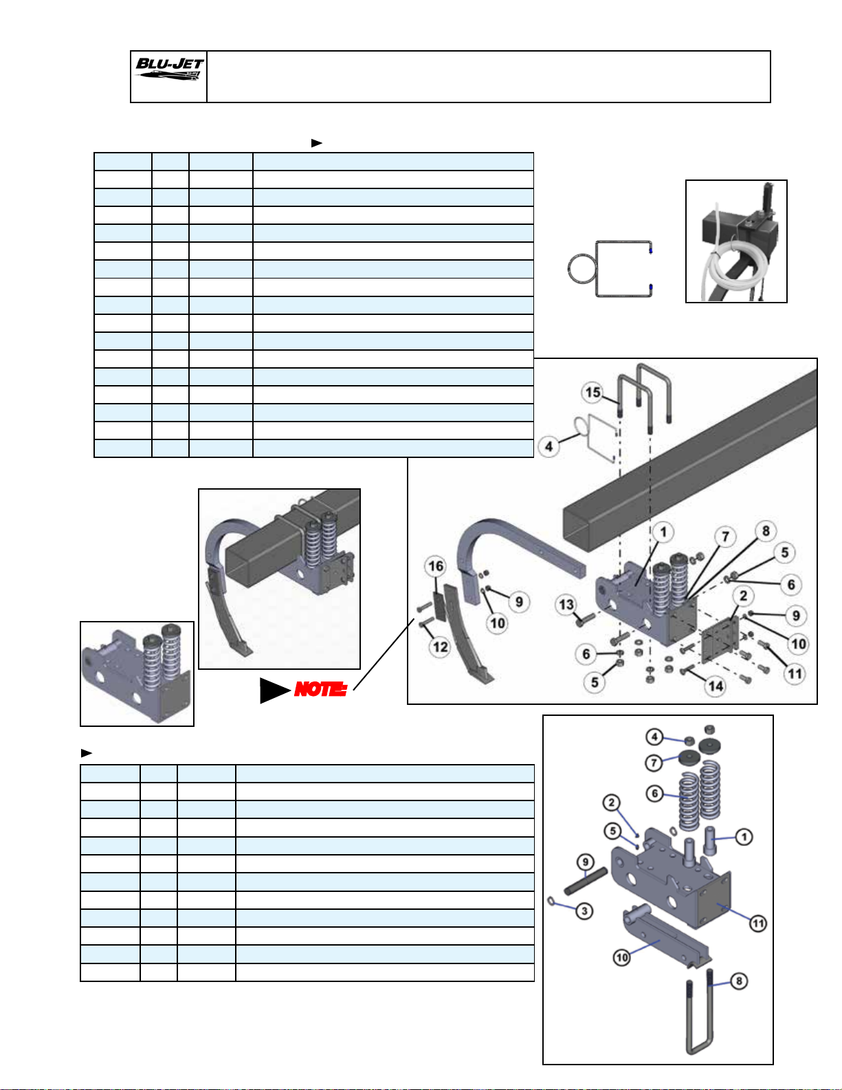
AT6020
AAM2134 1-1/4” SCS With Shank & Coulter
AAM2134 Row Clamp 1-1/4” EdgeBent SCS With Shank & Coulter Mount 6” x 6”
BOM ID Qty Item No Description
1 1 AM2155 ASSEMBLY, SPRING BUNDLE, EDGEBENT SHANK
2 1 AM2699 BRACKET, SPRING BUNDLE FLATBACK
3 1 AP2125 SHANK, 1-1/4” X 2” EDGE BENT
4 1 AP2283-1 HOSE RETAINER, 6” X 6”
5 6 BP3034 NUT, HEX, 3/4”-10, GRADE 2, PLATED
6 6 BP3035 WASHER, LOCK, 3/4”, PLATED
7 4 BP3038 NUT, HEX, 5/8”-11, GRADE 2
8 4 BP3039 WASHER, LOCK, 5/8”, PLATED
9 4 BP3042 NUT, HEX, 1/2”-13, GRADE 2, PLATED
10 4 BP3043 WASHER, LOCK, 1/2”, PLATED
11 4 BP3097 HEX CAP SCREW, 5/8”-11 X 1-1/2”, GRADE 5, PLATED
12 2 BP3128 HEX CAP SCREW, 1/2”-13 X 2-1/2”, GRADE 5, PLATED
13 2 BP3141 HEX CAP SCREW, 3/4”-10 X 3”, GRADE 5, PLATED
14 2 BP3229 BOLT, CARRIAGE, 1/2”-13 X 2-1/2”, GRADE 5, PLATED
15 2 BP3350 U-BOLT, 3/4”-10 X 6”W X 7-11/16”L, PLATED
16 1 CM2311 KNIFE WASHER
6” x 6” Hose Retainer,
(AP2283-1) Place
at each shank to
secure coiled length
of 3/8” EVA hose as
shown.
NOTE:
No threads
in shear
area
AM2155 Assembly, Spring Bundle, EdgeBent Shank
BOM ID Qty Item No Description
1 2 AM2156 SPRING SLEEVE
2 1 AP2166 CAPPLUG, GC-5 GREASE ZERK
3 2 AP2407 SNAP RING, 1” EXTERNAL, HEAVY DUTY
4 2 BP3027 NUT, HEX LOCK, 3/4”-10, GRADE 2, PLATED
5 1 BP3072 GREASE ZERK, 1/4”-28
6 2 BP3104 SPRING, 2.64” OD X 8.625” OAL, .4375” WIRE DIAMETER
7 2 BP3105-1 SPRING PLUG
8 1 BP3106 U-BOLT, 3/4”-10 X 3-1/4”W X 11-3/4”L
9 1 EM2959 PIVOT PIN, 1” X 6-13/16”
10 1 EM2977 INSERT, EDGEBENT SHANK
11 1 EM2978 SPRING BUNDLE BASE
95

AT6020
Manual Holder
AAM2640 MANUAL HOLDER WITH 6” X 6” MOUNTING
BOM ID Qty Item No Description
1 1 AM7640 BRACKET, MOUNTING, MANUAL HOLDER
2 1 AP4254 MANUAL HOLDER
3 3 BP3001 NUT, HEX, 3/8”-16, GRADE 2, PLATED
4 3 BP3002 WASHER, LOCK, 3/8”, PLATED
5 1 BP3006 HEX CAP SCREW, 3/8”-16 X 1”, GRADE 5, PLATED
6 1 BP3351 U-BOLT, 3/8”-16 X 6”W X 7”L, PLATED
96

AT6020
Impellicone and Mounting Hardware
AAM2635 IMPELLICONE 13 PORT, MOUNT & HARDWARE, 6” X 6”
BOM ID Qty Item No Description
1 1 AM7639 BRACKET, IMPELLICONE MOUNT
1A 1 CP2310 1’’ HOSE BARB
2 2 BP3001 NUT, HEX, 3/8”-16, GRADE 2, PLATED
3 2 BP3002 WASHER, LOCK, 3/8”, PLATED
4 1 BP3351 U-BOLT, 3/8”-16 X 6”W X 7”L
5 1 CP2564 IMPELLICONE, 13 PORT
AAM2636 IMPELLICONE 18 PORT, MOUNT & HARDWARE, 6” X 6”
BOM ID Qty Item No Description
1 1 AM7639 BRACKET, IMPELLICONE MOUNT
1A 1 CP2310 1’’ HOSE BARB
2 2 BP3001 NUT, HEX, 3/8”-16, GRADE 2, PLATED
3 2 BP3002 WASHER, LOCK, 3/8”, PLATED
4 1 BP3351 U-BOLT, 3/8”-16 X 6”W X 7”L
5 1 CP2565 IMPELLICONE, 18 PORT
97

AT6020
SuperShooter III Parts AAM3514
98
 Loading...