

Page 1
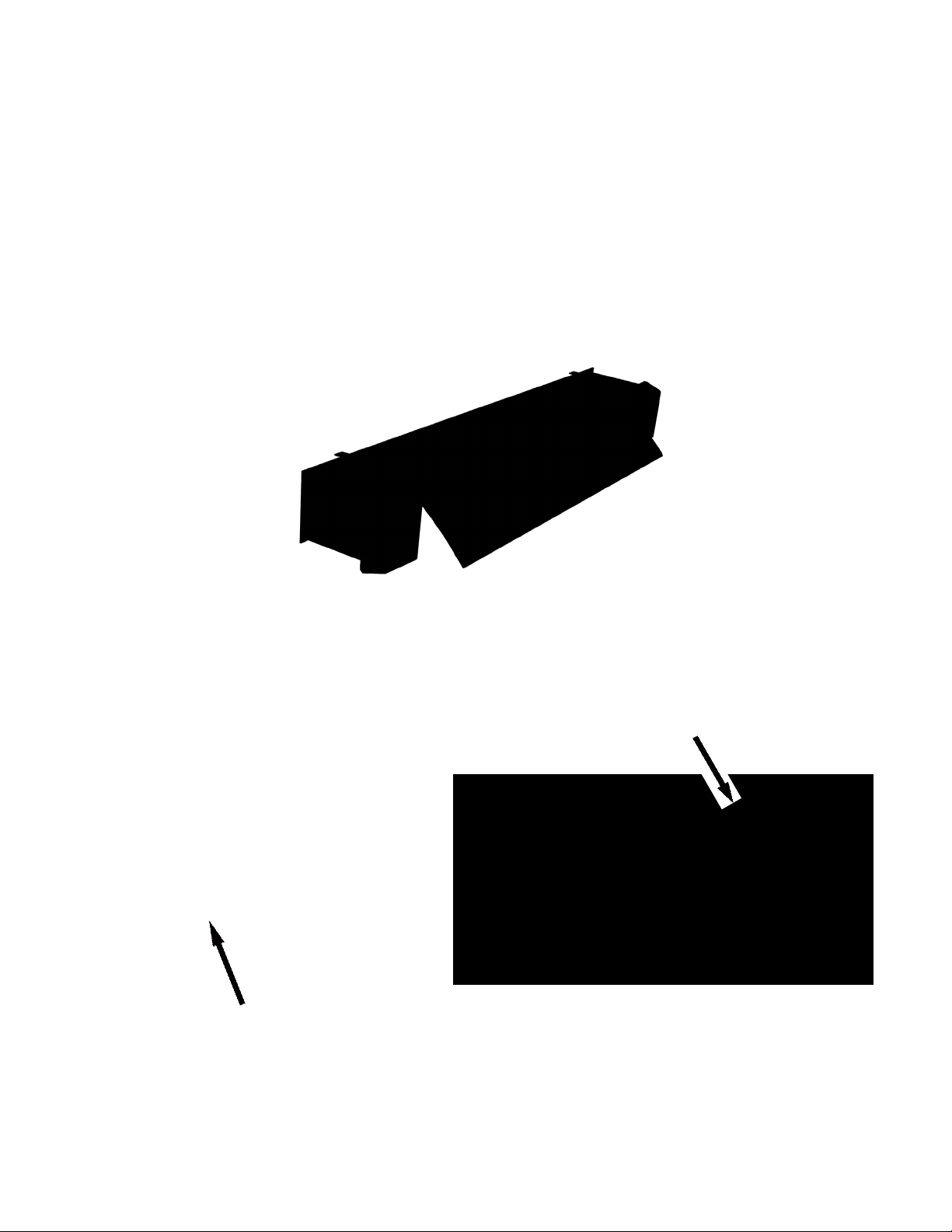
OWNER’S MANUAL AND INSTALLATION GUIDE FOR
EZ-PULL EDGE-OF-DOCK LEVELER (EP)
EP HYDRAULIC OPTION
FOR EZ-PULL EDGE-OF-DOCK LEVELER (EP)
OR LO-DOCK LEVELER(LD)
HYDRAULIC RETRO-FIT OPTION
SERVICE YOU CAN STAND ON
01032017
1
Page 2

Rev. 11-16
DO NOT INSTALL, OPERATE OR SERVICE
PRODUCT WITHOUT READING AND FULLY
UNDERSTANDING ALL SAFETY PROCEDURES,
WARNINGS, INSTALLATION AND OPERATING
INSTRUCTIONS ENCLOSED IN THIS MANUAL.
TABLE OF CONTENTS
EZ-Pull Edge-of-Dock Leveler Owners Manual ......................................................................................... 3
Engineering Design.....................................................................................................................................2
Dock Parameters ........................................................................................................................................2
..............................................................................................................4
Safety Precautions......................................................................................................................................5
Tool List ............................................................................6
Type I Installation Instructions for Edge-of-Dock Leveler............................................................................6
Type II Installation Instructions for Edge-of-Dock Leveler...........................................................................8
Operating Instructions...............................................................................................................................10
Maintenance 11
Troubleshooting
Assembly Drawing ....................................................................................................................................12
EPHYDRAULIC Option for EZ-Pull Edge-of-Dock Leveler (EP) or Lo-Dock Leveler (LD) ....................13
Installation Instructions for Factory Issued Hydraulic Unit
Wiring Schematic......................................................................................................................................15
Operating Instructions...............................................................................................................................18
Troubleshooting Guide .............................................................................................................................19
Hydraulic Retro-Fit Option for EZ-Pull Edge-of-Dock Leveler (EP) or Lo-Dock Leveler (LD) .............20
Installation Instructions for In-Field Retro-Fit of Existing Leveler Unit ......................................................20
........................................................................
11
14
Bluff Warranty and Returned Goods Authorization .................................................................................22
2
Page 3

Rev. 11-16
EZ-PULL EDGE OF DOCK LEVELER
EZ-PULL EDGE OF DOCK LEVELER
OWNERS MANUAL
*
*Read entire manual prior to unit installation.
Engineering Design
The Bluff EZ-Pull dock leveler design offers a tremendous ergonomic solution when compared to other available
dock leveler designs. The simple, smooth performance and easy to position design eliminates the lifting and difcult
positioning factors associated with hook type designs.
The Bluff latch assembly allows the operator to easily position the unit. A pull and push action on the EZ-Pull handle
activates the unit, moving the lip forward onto the trailer oor. Retraction and storage of the unit after use is also
accomplished by a pull and push action on the EZ-Pull handle. Simply pull the handle back until the leveler lip is
removed from the trailer oor and then push the handle forward to allow the unit to store.
Dock Parameters
The EZ-Pull dock leveler will accommodate a maximum of ve (5) inches above dock and ve (5) inches below
dock, providing 18.5% grade down and 20% grade up. This is acceptable for most gas or propane forklifts but is
not suitable for most pallet trucks or many electric forklifts.
• Freight trailers range in height from 46 to 56 inches; therefore the EZ-Pull leveler should be
mounted at 51 inches above the driveway.
• Refrigerated trailers range in height from 50 to 60 inches; therefore the EZ-Pull leveler should be
mounted at 55 inches above the driveway. In addition, this application requires a Reefer Lip (17’
lip length) to accommodate the offset floor of the trailer.
• Flatbed trailers have a wide range of trailer heights. Dock boards or other equipment may be
needed for extreme height variations.
• Containers have variations in both floor heights and door configurations.
• Captive fleets require mounting midway between lowest and highest trailer, provided ±5" range
is maintained.
Pallet trucks and electric forklifts can be used with trailers three (3) inches above and three (3) inches below dock
level. Dock boards or other equipment may be needed to accommodate a greater service range for pallet jacks
and electric forklifts. This is due to limited clearance and gradeability of that equipment.
EZ-Pull Dock Levelers WILL NOT accommodate refrigerated and freight trailers at a single dock
location due to limitations specied above.
Solutions:
1. Mount separate EZ-Pull levelers at different heights to handle both types correctly.
2. Mount an EZ-Pull leveler with Reefer Lip at 55 inches and use Bluff Wheel Risers to raise low
trailers to proper height.
Declining and inclining drives require special dock specication. Call for more information.
3
Page 4

Rev. 11-16
assembly for ease of positioning. Unit conforms to ANSI Standard MH 30.1.
EZ-PULL EDGE OF DOCK LEVELER
Product Specications & Features
The Bluff EZ-Pull dock leveler is designed with a fully hinged lip and utilizes a torsion spring counterbalance
Three piece steel construction. Lip and ramp
are constructed of 50,000 psi yield strength
steel tread plate.
Mechanical latch produces
lip extension.
Single torsion spring provides
Z shaped bumper beams with
replaceable rubber bumpers.
• Bluff’s EZ-Pull leveler has 5 inches above and below dock surface operating range for propane and gas
trucks and 3 inches above and below dock surface operating range for pallet jacks and electric forklifts.
Positioning tabs
for installation.
• Lip section tilts up to 1 inch for out of level compensation.
• Unit is also designed to oat allowing for vertical corner deection when the lip is in contact with truck bed.
• Positioning tabs ensure correct height placement on dock surface during installation, effectively making the
Bluff leveler the
EASIEST TO INSTALL IN THE INDUSTRY.
counterbalance on lip section
for ease of positioning.
• One year structural warranty as dened on page 22.
4
Page 5

Rev. 11-16
EZ-PULL EDGE OF DOCK LEVELER
Safety Precautions
READ AND UNDERSTAND ALL SAFETY PRACTICES AND OPERATING INSTRUCTIONS
before installing, servicing or operating the dock leveler. Failure to do so could result in
damage to unit, to property, and personal injury to operator.
1. Do not stand between leveler and trucks backing up to dock.
2. Do not operate the leveler with equipment, material or people on the deck section
of the leveler.
3. Do not stand or travel across leveler unless lip is placed securely on truck bed oor.
4. Never attempt to work under the dock leveler without properly securing the front
and center sections.
5. Keep clear of dock leveler while in operation.
6. Do not exceed capacity rating.
7. If dock leveler is not operating normally, discontinue use. Request maintenance
personnel to inspect and contact your local Bluff dealer if necessary.
8. Keep clear of all pinch points that could cause injury.
9. Do not use leveler if it appears to be damaged or broken.
10. Damage to leveler could occur if product is misused or used in an abusive manner.
11. For additional information or concerns, contact your local Bluff representative.
5
Page 6

Page 7

Rev. 11-16
EZ-PULL EDGE OF DOCK LEVELER
8. Position the bumpers ush with top of mount plate and butted up to the sides of the mount plate.
9. Mark the bottom hole location of bumper beam, drill an anchor hole and install a ¾" x 4" wedge anchor
bolt.
10. Re-position the bumper on the dock and weld to embedded channel and secure the bottom of the
bumper anchor bolt and nut.
11. Re-grease the unit as welding may burn out some grease in hinge tubes.
12. Re-paint any burned areas. Rustoleum smoke grey (7786) or blue (7727) aerosol.
13. The latch is factory installed with notch against mount plate. Latch should swing freely when leveler is in
its rest position.
Latch Position
(Indicated in red
for clarity)
14. Remove bolt from bottom of handle and position handle into sleeve with bend facing away from dock
face. Re-install bolt and nut into bottom of handle.
15. Test unit for correct operation. (See operating instructions for mechanical levelers.)
7
Page 8
Rev. 11-16
Type II Installation Instructions
Mechanical Edge-of-Dock (EP)
TYPE II: Dock edge without imbedded steel channel.
EZ-PULL EDGE OF DOCK LEVELER
CAUTION: STAND CLEAR OF UNIT WHEN CUTTING STEEL BANDING.
NOTE: REMOVE HANDLE AND BUMPERS BEFORE BEGINNING THE INSTALLATION.
Handle is attached to mount plate for shipping purposes only.
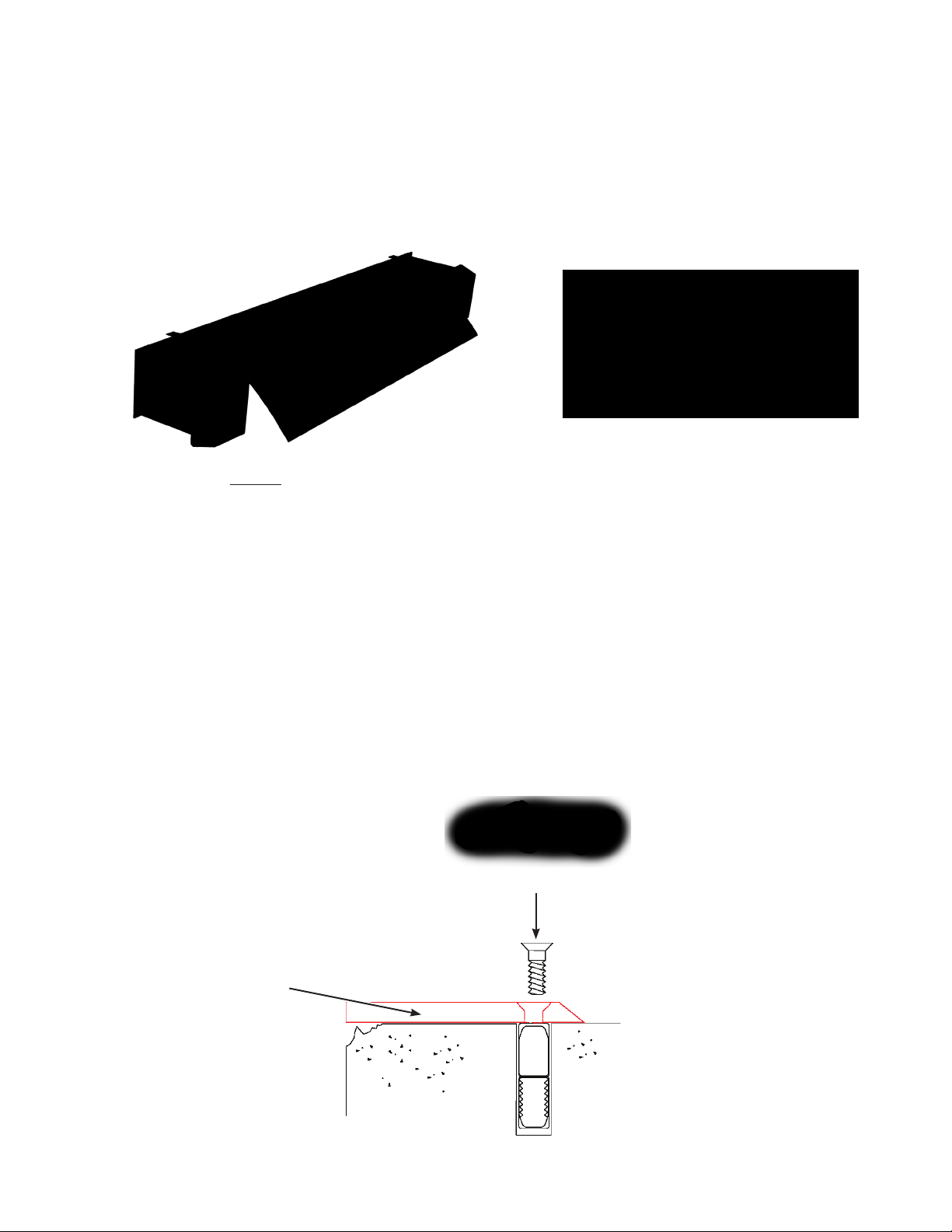
1. Docks without imbedded steel channel require the installation of an approach plate, such as the Bluff
EPAP12 model, in conjunction with a leveler unit.
2. Center the beveled approach plate in the desired location ush with the dock face. Cut if required to t door
opening.
An approach plate requires 5 heavy duty expansion shield anchor bolts with ½" at head
socket cap screws such as can be found in Bluff EP Kit 2. Locate the approach plate and
drill pilot anchor holes with a 9/16" concrete drill bit. Remove approach plate and drill over
pilot holes with a 7/8" concrete bit. Install expansion shield into holes (insert with threads on
bottom). Re-position approach plate and anchor.
EXPANSION SHIELD ANCHORS
Approach Plate
(EPAP12)
8
Page 9
Rev. 11-16
EZ-PULL EDGE OF DOCK LEVELER
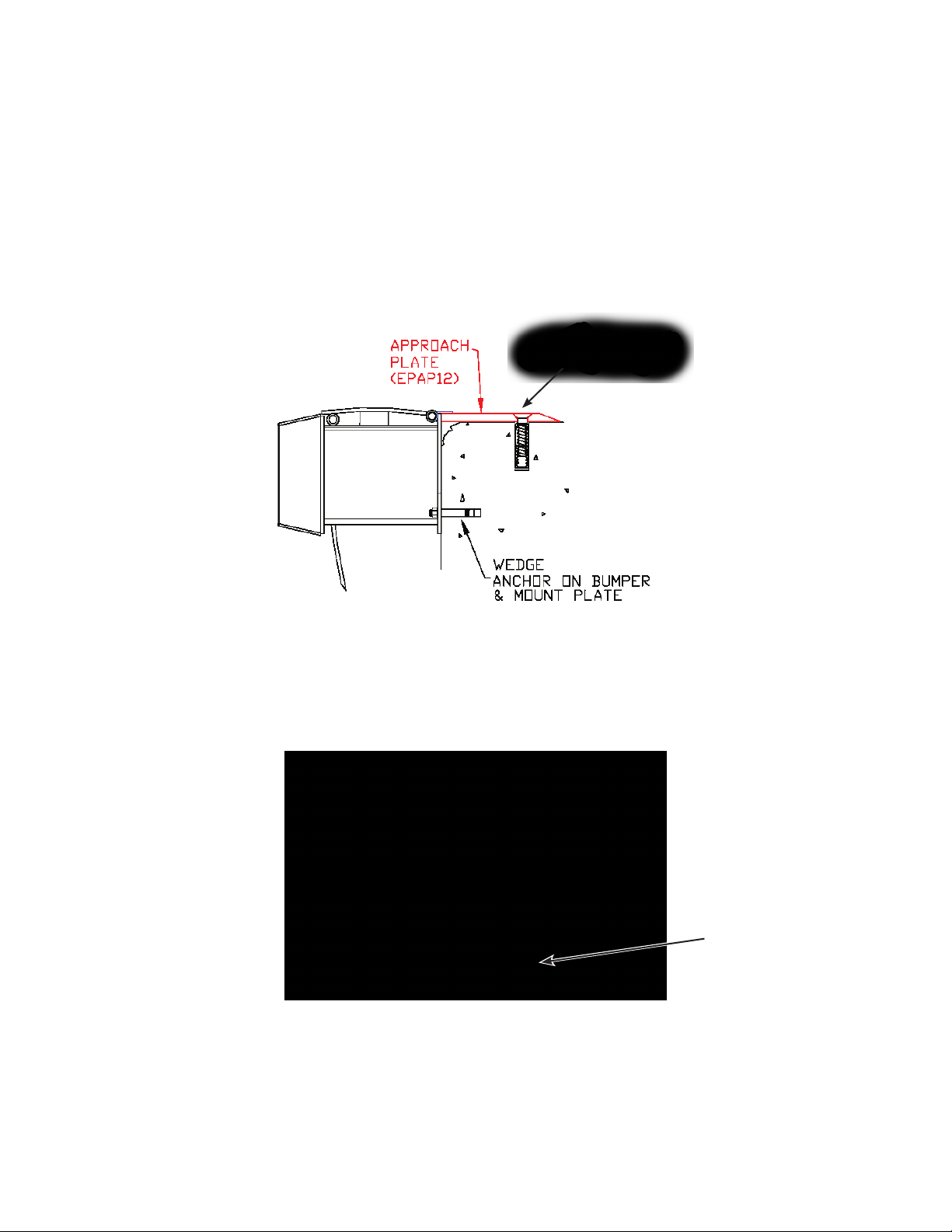
3. Center the EZ-Pull leveler against the dock with the positioning tabs (see page 4) resting on top of the
approach plate.
4. Tack the top of the mount plate at the center to the approach plate.
5. Make certain that the leveler is straight and plumb (shim as necessary).
6. Drill 3/4" anchor holes along the mount plate and install 5 each ¾"x 4" wedge anchors.
7. Weld top of mount plate to approach plate with a continuous weld from center out.
8. Remove weld slag and re-grease as needed as welding may burn out grease from hinges.
9. Re-paint any burned areas. Rustoleum smoke grey (7786) or blue (7727) aerosol.
10. The latch is factory installed with notch against mount plate. Latch should swing freely when leveler
is in its rest position.
Catch Position
(Indicated in red
for clarity)
11. Remove the bolt from the handle and position it into sleeve tube with bend facing away from dock face.
Re-install bolt and nut into bottom of handle.
12. Test unit for proper operation. (See operating instructions for mechanical levelers.)
9
Page 10

Rev. 11-16
EZ-PULL EDGE OF DOCK LEVELER
Mechanical EDGE-OF-DOCK or LO-DOCK
Operating Instructions
DO NOT ACTUATE THE
EDGE-OF-DOCK LEVELER
WITHOUT A TRUCK IN PLACE
Step 1: Pull the EP handle up until the dead bolt hits the bottom of the 2-inch-square tube sleeve.
Step 2: Pull the handle back until the latch mechanism falls into catch position.
Step 1 Step 2a Step 2b
Latch Position
(Illustrated in red for clarity)
Step 3: Push the handle forward to extend the unit outward toward the truck bed.
Step 3
Step 4: Continue to push forward until the front lip rests fully on the truck bed.
Step 5: Return the handle to its rest position while in use.
Step 6: When returning the unit to its stored position, repeat Step 1.
Step 7: Pull back the handle until the front lip clears the truck oor then allow the weight of the leveler to
drop the unit into its rest position.
Step 8: Return the handle to its rest position.
10
Page 11

Rev. 11-16
EZ-PULL EDGE OF DOCK LEVELER
Maintenance
The Bluff EZ-Pull Leveler will provide years of efcient operation if properly maintained. Preventive maintenance
should be performed every six months or as needed for normal usage. For efcient operation and proper maintenance
of Levelers used for multiple shifts (above normal usage), maintenance should be performed every 30 days.
1. Cleaning: Check hinge tube areas for any debris. Clean hinges with wire brush to remove any
foreign objects.
2. Grease: The unit should be greased twice a year or as needed – grease zerts are located
underneath the deck of the leveler.
3. Structural Check: Check unit over for any obvious structural wear. Check hinge tubes for any
signs of cracking or wearing.
4. Spring Assembly: Check spring assembly to assure a proper float in the leveler deck. Check
spring linkage rod for any signs of bending.
5. Handle Check: Check EZ-Pull handle for any signs of bending or cracking. Improper handle
bend may result in unit not latching properly.
6. Latch: Check the latch and latch catch for signs of wear on surfaces. Too much wear can
decrease height up allowance and may keep latch from disengaging.
Any damaged parts should be replaced immediately and can be purchased from your local Bluff distributor.
Bluff levelers feature a modular design, allowing for easy replacement.
Troubleshooting
The Bluff EZ-Pull Edge of Dock Leveler is a mechanical device requiring leverage and gravity to operate
efciently.
1. When I raise the dock leveler, the front lip does not extend outward.
• Check to ensure latch is attached to unit.
• Check to ensure latch notch is facing the dock.
• Check latch assembly for damage or excessive wear.
2. When I raise the dock leveler, the handle hits the dock surface.
• Check to ensure handle is located correctly in holster. Handle and bend facing away from
dock face (toward trailer) when stored in position.
• Check handle for damage.
3. The leveler will not raise enough to allow latch to catch.
• Check for proper tube clearance. Tubes should be 1/8+" higher than dock surface. Deck
needs to rotate to approximately the one o’clock position.
• Check handle for any damage.
• Check hinge tubes for any debris. Wood, nails, etc. can prevent proper rotation.
4. The leveler is difficult to raise and lower in position.
• Check hinge tubes. Clean any debris or foreign objects from hinges. Use wire brush if
necessary.
• Check hinge tube lubrication. Grease unit thoroughly.
*Important: Specify Model Number and Serial Number when ordering parts
11
Page 12

Rev. 11-16
Assembly Drawing
EZ-PULL EDGE OF DOCK LEVELER
* Important: Specify Model Number and Serial Number when ordering parts.
PART # ITEM DESCRIPTION
EP72LIP EZ-Pull Front Lip Assy (Std) – 15" Lip Length
EP72LIPR EZ-Pull Front Lip Assy (Reefer) – 17" Lip Length
EP72DECK EZ-Pull Center Section Assy
EPBUMPBASE EZ-Pull Bumper Support
EPSA EZ-Pull Spring Assy (includes Linkage Rod)
EPRB10 EZ-Pull Molded Bumper – 13" x 10" x 4" w/Fasteners
EPLINKROD EZ-Pull Linkage Rod w/Pins
EPHANDLE EZ-Pull Handle w/Bolt
EPLAT EZ-Pull Latch w/Bolt
EPCB10 EZ-Pull Bumper Complete w/Base
12
Page 13
Rev. 11-16
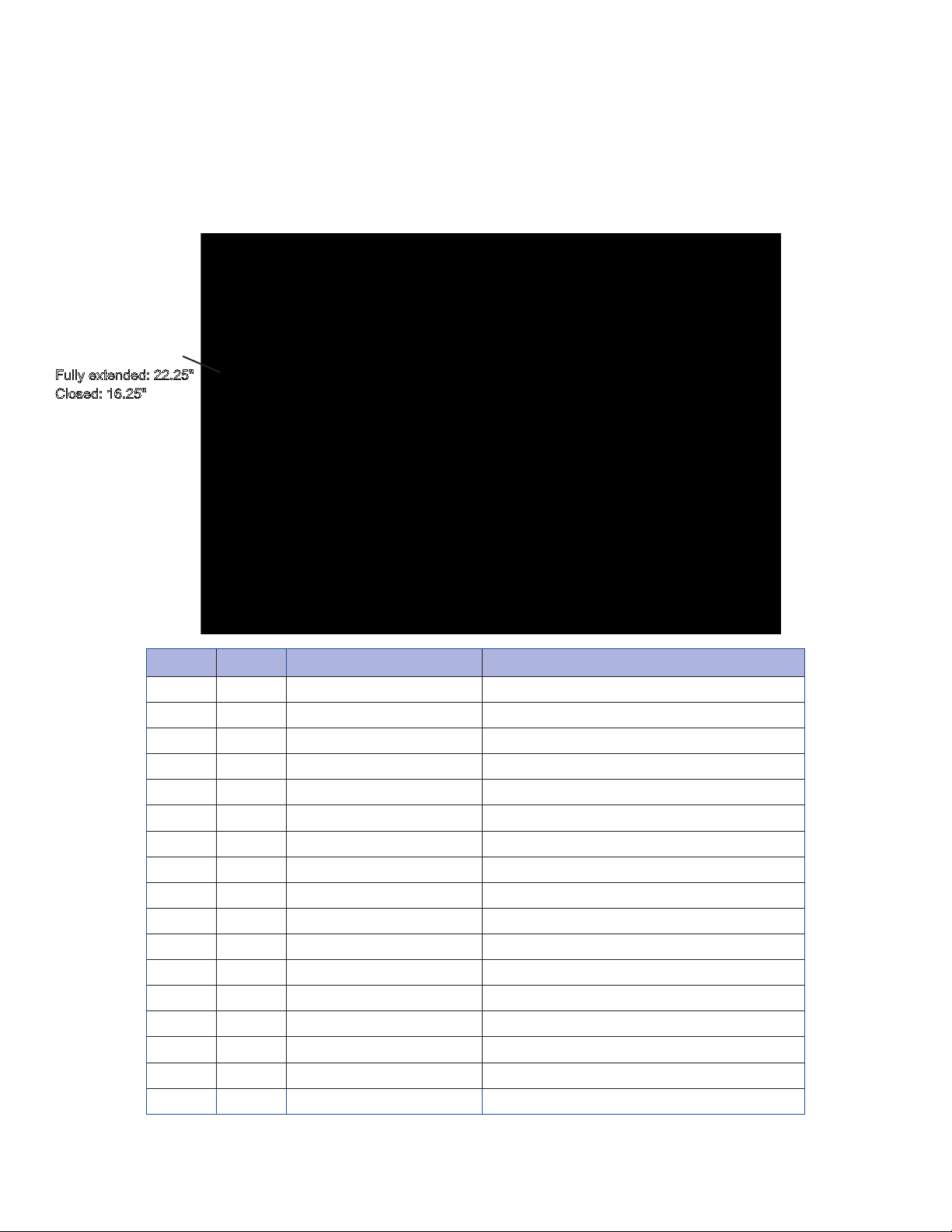
INSTALLATION GUIDE FOR EPHYDRAULIC OPTION
MHYDCYLINDER
Fully extended: 22.25"
Closed: 16.25"
EPHYDRAULIC OPTION
for Bluff EDGE-OF-DOCK and LO-DOCK Levelers
ITEM QTY PART # DESCRIPTION
A 1 MHYDCYLINDER 6" STROKE, TIE ROD HYD.CYLINDER.
B 2 Y3414B FITTING REDUCER
C 1 MADAPTER90 90 DEG. ELBOW SHORT
D 1 MADAPTER90XL 90 DEG. ELBOW LONG
E 1 YFCV FLOW CONTROL VALVE
F 1 MPOWERUNIT AC HYD-PWR UNIT
G 1 Y90ML 90 DEG. ELBOW
H 1 Y30HH 30" HYDRAULIC HOSES
I 2 ** SOLENOID CONNECTORS
J 2 F3834H PUMP MOUNT BOLTS
K 1 EPHUBKT EP-HYD. UPPER BRACKET
L 1 EPPMBKT EP PUMP MOUNT BRACKET
M 1 MPUSHBUTTON WALL MOUNTED PUSH BUTTON
N 1 M442GANGBOX ELECT. JUNCTION BOX
O 1 M123RIGIDNIPPLE 3" PIPE FITTING
P 1 EPHLBKT EP-HYD. LOWER BRACKET
Q 1 EPHDS EP-HYD. DECK STOP
** Included MPOWER UNIT
13
Page 14
Rev. 11-16
EPHYDRAULIC OPTION
Complete Hydraulic Set-Up Installation Instructions
For Factory Issued Hydraulic Unit
NOTE: FOR LO-DOCK APPLICATIONS CALL YOUR LOCAL BLUFF DEALER AT 800-433-2212.
1. Prior to mounting, refer to EZ-Pull dock parameters and mounting instructions for Mechanical Edge-of-Dock
Levelers or Lo-Dock Levelers for mounting the leveler unit.
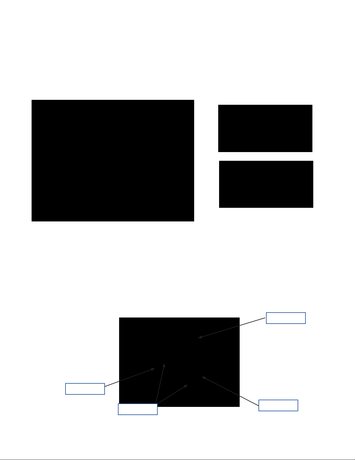
2. Lift the lip of the EZ-Pull leveler to expose the brackets as shown below.
3. Anchor the mount plate as shown below.
4. Weld EPHLBKT lower bracket in-line with the EPHUBKT upper bracket.
EPHUBKT
EPPMBKT
Anchors
EPHLBKT
14
Page 15

Rev 11-16
5. Mount the MPOWERUNIT on the pump mount bracket EPPMBKT.
6. Mount the MHYDCYLINDER onto the lower bracket EPHLBKT.
EPHYDRAULIC OPTION
3/8"-16 x ¾" Bolts
7. Install and connect hoses as shown below. When connecting the hydraulic hoses to the fitting use Teflon tape.
8. Mount the switch (MPUSHBUTTON) on the interior of the building wall.
15
Page 16

Rev. 11-16
EPHYDRAULIC OPTION
CAUTION: ONLY QUALIFIED PERSONNEL SHOULD ATTEMPT TO
PERFORM THE FOLLOWING WIRING INSTRUCTIONS.
Push button unit
NOTE: Customer to furnish
wire for push button to
motor and push button to
plug. 115 VAC plug required.
BLK
WHT
GRN
FWD
REV
SWITCH
CUSTOMER
SUPPLIED
BLUFF SUPPLIED
CUSTOMER SUPPLIED
JUNCTION
BOX
JUNCTION BOX
BLK
WHT
GRN
SWITCH
BLK
WHT
GRN
GRN
BLK
WHT
16
Page 17

Rev 11-16
EPHYDRAULIC OPTION
Wiring Instructions:
NOTE: All wiring should be done in accordance with local electric codes.
The unit requires 120 Volt, Single Phase current.
The photo below shows how to hook the incoming power and the connection to Junction Box on the
unit. The Push Button Switch Box and the Junction Box have been pre-wired and all that is needed is
the incoming power, and the connection from the Push Button and the Junction Box. The customer
supplies the incoming current wires and connection from the Push Button and the Main Junction Box.
Use #14 stranded wire, with conduit according to your local electric code.
Be sure and observe all local Electric Codes.
Junction Box Push Button Box
The direction of travel can be switched by swapping leads 4 and 5, or by swapping the connectors on the valve body.
17
Page 18

Rev. 11-16
EPHYDRAULIC OPTION
IMPORTANT
9.
Items ship without hydraulic fluid. FILL THE RESERVOIR WITH COMMON GRADE HYDRAULIC
FLUID. (Common grade fluid is ISO 46). For areas of sub-freezing temperatures, a lighter grade
(ISO 32) may be used.
10. Power the MPOWERUNIT and jog the motor to test wiring.
11. Jog motor to extend the MHYDCYLINDER such to attach to the upper bracket EPHUBKT utilizing the
provided pin and keepers.
12. Carefully lower the lip to its rest position.
13. Press the forward and reverse button to complete a full cycle.
14. Refer to the trouble-shooting guide if unit does not function properly.
18
Page 19

Rev. 11-16
EPHYDRAULIC OPTION
Operating Instructions
Hydraulic Edge of Dock Levelers
Step 1: With truck back into position and trailer door open, depress the reverse button until the latch falls
into position. See illustration below.
Step 2: Once the latch falls into position, release the reverse button and depress the forward push button.
Step 3: The front lip will begin to extend forward, continue to hold the forward button until the front lip rests
on the truck oor or the latch kicks off and the front lip lowers onto the truck oor.
Step 4: To return the hydraulic leveler to its resting position, for proper storage, depress the reverse button
until the front lip clears the truck bed and raises into a vertical position.
Step 5: The hydraulic uid will return to the tank. The deck section will slowly lower to its resting position
parallel to the dock face.
NOTE: When Leveler is not in use, keep in lowered, stored position.
19
Page 20

Rev. 11-16
EPHYDRAULIC OPTION
Troubleshooting Guide
(For all types of edge of dock units)
SYMPTOM: POSSIBLE PROBLEM:
Leveler will not pivot No grease in hinge and tube joints.
No hydraulic uid in tank.
Missing or broken component.
Check for obstruction preventing proper operation.
Leveler will not extend forward Latch installed incorrectly. (Reverse)
Latch did not engage.
Leveler installed below the dock level and the unit
not allowed to pivot back enough to for the latch to
engage.
No hydraulic uid in unit, leak in hose.
Broken or missing component.
Lip not returning to stored position Latch not disengaging.
Insufcient grease in hinges.
Check for debris or obstructions.
Leveler not moving (motor running) Check uid level.
Pushing wrong button.
Faulty hose, damaged value stem.
Wiring wrong, damaged components.
Leveler will not move (motor not running) Check wiring, voltage, etc.
Motor damaged.
Bad push button switch.
Power Outage. Unit cannot be worked manually.
20
Page 21

Rev. 11-16
Retro-Fit
RETRO-FIT OPTION
Complete Hydraulic Set-Up Installation Instructions
For In-Field Retro-Fit of Existing Leveler Unit
NOTE: The leveler selected for the retro-t hydraulic package must be in acceptable working condition.
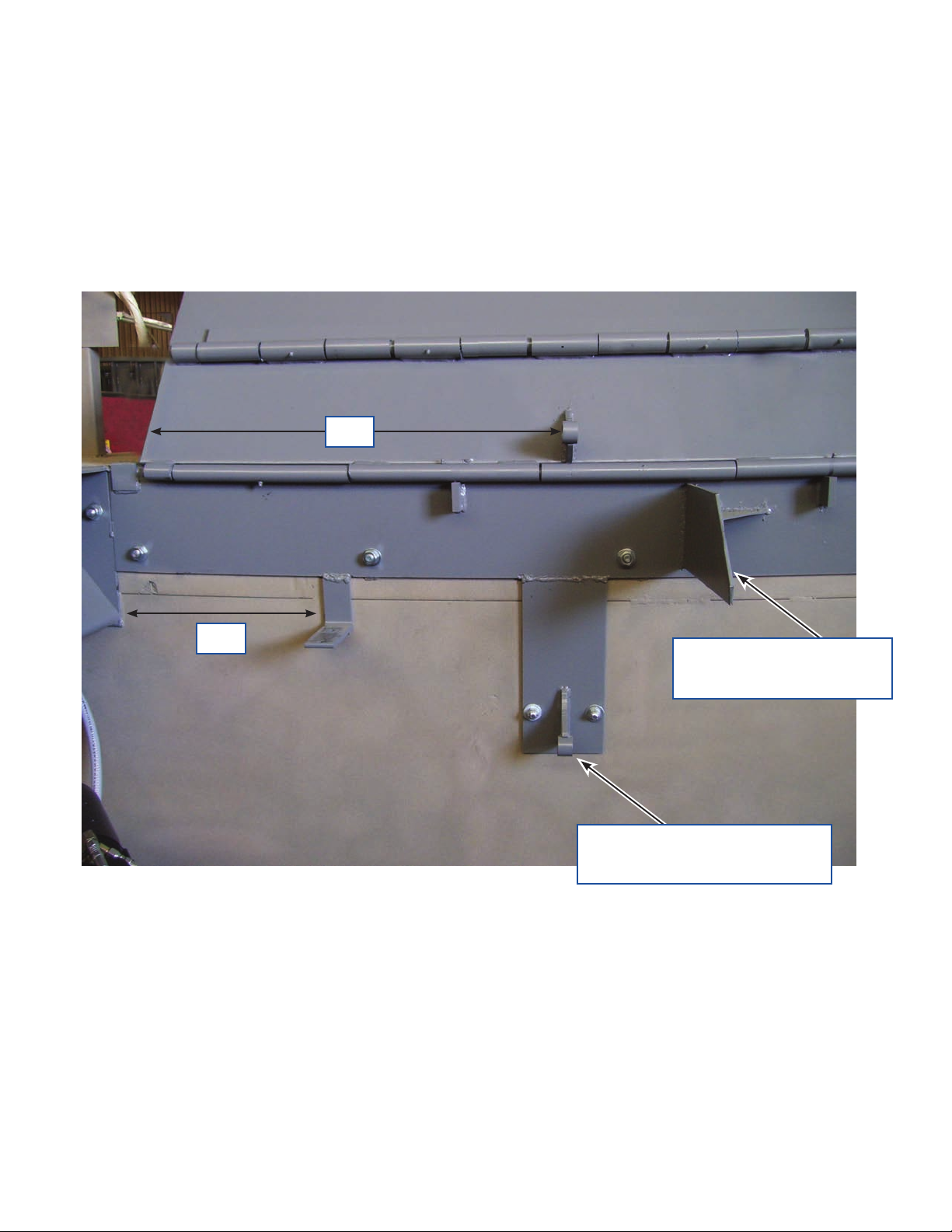
1. Lift the front lip of the EZ-Pull leveler to expose the brackets as shown below.
2. Remove the spring assembly leaving the deck stop and gusset.
Deck stop
Spring assembly and tube
Deck stops left of the spring assembly
and tube must be removed to accept
hydraulic brackets.
21
Page 22
Rev. 11-16
Complete Hydraulic Set-Up Installation Instructions
For In-Field Retro-Fit of Existing Leveler Unit (continued)
3. Clean the surface and weld the brackets as shown below.
29"
RETRO-FIT OPTION
16"
Align lower bracket tube with
upper tube and weld.
4. Anchor the lower bracket to side of dock.
5.
To complete the retro-t follow steps 5 thru 14 of the complete EPHYDRAULIC option.
Weld bracket to existing
deck stop and gusset
22
Page 23

Rev. 11-16
Bluff Warranty
Bluff Manufacturing warrants their products to be free from defects in material and workmanship for a period
of one year from shipping date to original purchaser. Yard ramp pumps and EOD hydraulic power units are
warrantied for 90 days from shipping date to original purchaser. Warranty eligibility requires all products are
used and serviced in accordance with the company’s recommendations, product selection guides, product
manuals and installation instructions.
Bluff Manufacturing’s obligation under this warranty shall be limited to the repair, by Bluff Manufacturing or a
Bluff Manufacturing authorized technician, or exchange of any part of parts which may prove defective under
normal service within the time limitations set forth above, and which our examination shall disclose to our
satisfaction to be defective. Bluff Manufacturing requires the purchaser to send date stamped photographs
for initial review of warranty claim products.
This limited warranty does not cover any defects, malfunction or failure caused by or resulting from improper
or unauthorized service, maintenance, installation repair or use not in conformance or accordance with Bluff
Manufacturing’s recommendations, product selection guides, product manuals or installation instructions
and the intended use and capacities or specications or from abuse, neglect, accident, weather related
issues or any other cause beyond the control of Bluff Manufacturing. This limited warranty is made only to
the original purchaser, which shall be deemed to mean that person or organization to which the product is
originally shipped or installed.
Bluff Manufacturing does not approve nor authorize any other person or entity to obligate Bluff
Manufacturing to any other liability not described herein concerning the sale of its products.
Bluff Manufacturing shall not be liable for any incidental or consequential damages. And liability hereunder
is expressly limited to repair or replacement of any part or parts which may prove defective within the time
prescribed hereon.
This warranty is expressly in lieu of all other warranties, expressed or implied, including the warranties of
merchantability and tness for a particular purpose and all other obligations or liabilities on our part.
Bluff Returned Goods Authorization (RGA)
Before returning any merchandise for any reason whatsoever, it is necessary to contact Bluff Manufacturing
for approval. All requests must be submitted with a date stamped photograph of item to be returned. If
approval is given, an RGA number will be given by Bluff Manufacturing. This RGA number must appear on
all documents involving the returned goods.
Freight charges on all RGA’s must be PREPAID on returns but not warranties.
RGA numbers will not be issued after ninety (90) days from date of shipment, except for warranty items, by
Bluff Manufacturing or its designated representative.
A restocking charge of 25% will be made on all merchandise except as allowed under warranty claims.
Returns will not be allowed on any custom, special or worksheet required items and products in non-
resalable condition.
23
 Loading...