

Page 1

Bluezone Products, Inc. 225 Wildwood Avenue Woburn MA 01801
Bluezone® Model 2400
Air Purification System
Installation, Operation and Service
Manual
Page 2
Document #: BZ2400-0XX
1
Safety
This operation and service manual contains
important instructions and safety information
about the Bluezone Air Purification System.
Observe the following dangers, warnings,
cautions and notices when installing,
operating and servicing the Bluezone Model
2400.
Electrical System
Energized electrical circuits present a
potentially life-threatening hazard.
Ensure the unit’s power cord is unplugged
before performing any installation or service
work.
Ensure there are no other electrical power
circuits connected to the Bluezone Model
2400.
Follow all lockout/tagout procedures for all
electrical circuits.
System Operation
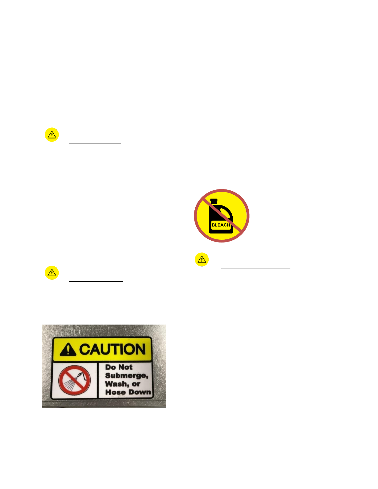
Never hose down the Bluezone Model 2400
or clean with a water jet. Direct flow of water
onto the catalyst can reduce its effectiveness
in eliminating ozone.
Turn off Bluezone units and cover with plastic
if the room is being hosed with water or
steam.
Do not operate the Bluezone Model 2400
while fogging the greenhouse or grow house
with chlorine, bleach or other disinfectant
solutions. Disinfectants can poison the
Bluezone catalyst and reduce its
effectiveness.
• Turn off the Bluezone Units if
disinfectant fogging or cleaning is
underway.
• Turn Bluezone units back on after
disinfectants have dissipated.
System Maintenance
The Bluezone Model 2400 contains 4 UV-C
light bulbs; the UV light is completely
contained inside the unit during operation.
The Bluezone Model 2400 has multiple safety
systems to ensure that you cannot view the
UV bulbs while they are operating.
Do NOT attempt to override the cover switch
to allow the bulbs to operate when the cover
is off.
Avoid exposure to direct or reflected UV-C
light.
Never look at an illuminated UV-C bulb
without proper eye protection against UV light
frequencies.
The UV-C lamps generate ozone. This ozone
is contained inside the Bluezone Model 2400.
Page 3
Document #: BZ2400-0XX
2
When conducting maintenance, power down
the unit and wait 15 minutes before removing
the cover.
There will be residual ozone inside the
Bluezone Model 2400.
Do not breathe air directly from inside the
unit.
Description
The Bluezone® Model 2400 is an air
purification device that eliminates airborne
contaminants including microbes (fungi, mold
and bacteria), odors and ethylene.
The Bluezone Model 2400 is designed for use
in cold storage and large walk-in coolers.
The Model 2400 can be hung or mounted to
the ceiling or wall, or located on a shelf.
The Bluezone Model 2400 draws in air
containing ethylene and mold that can lead to
early ripening and decay of FF&V, and
discharges air with a highly reduced
concentration of these impurities.
The facility, produce, food, and personnel
have no contact with the process that is
cleaning the air.
The unit is completely self-contained.
The Bluezone unit’s operation is controlled by
a microprocessor-based controller that
ensures safe operation at all times and alerts
the user to any system faults.
Specifications
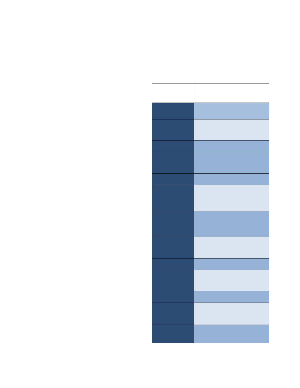
The specifications of the Bluezone Model
2400 are shown in Table 1.
Table 1: Bluezone Model 2400
Specifications
Specification
Category
Model 2400
Application
FF&V Cold Storage
Walk-in Coolers
Size
31” X 14” X 13.5”
79cm X 36 cm X 34 cm
Product Weight
25 lbs./11kg
Shipping Size
36” X 20” X 20”
91cm X 51cm X 51cm
Shipping Weight
28 lbs/13 kg
Operating
Environment
34°F – 104°F
1C – 40C
up to 90% RH
Storage
Environment
-4°F – 150°F
-20C – 65C
up to 90% RH
Treatment
volume
15,000 cubic feet
430 m3 per Bluezone
Input Voltage
120 or 240 VAC 1 Phase
Current
3 amps (at 120VAC)
1.5 amps (at 240VAC)
Power
300 Watts
Electrical
Connection
Standard 120/240 VAC cord with
pig tail for direct wiring or plug on
request
Mounting
Options:
Hung from ceiling, placed on
shelf/rack/cart, or mounted to wall
Page 4
Document #: BZ2400-045
3
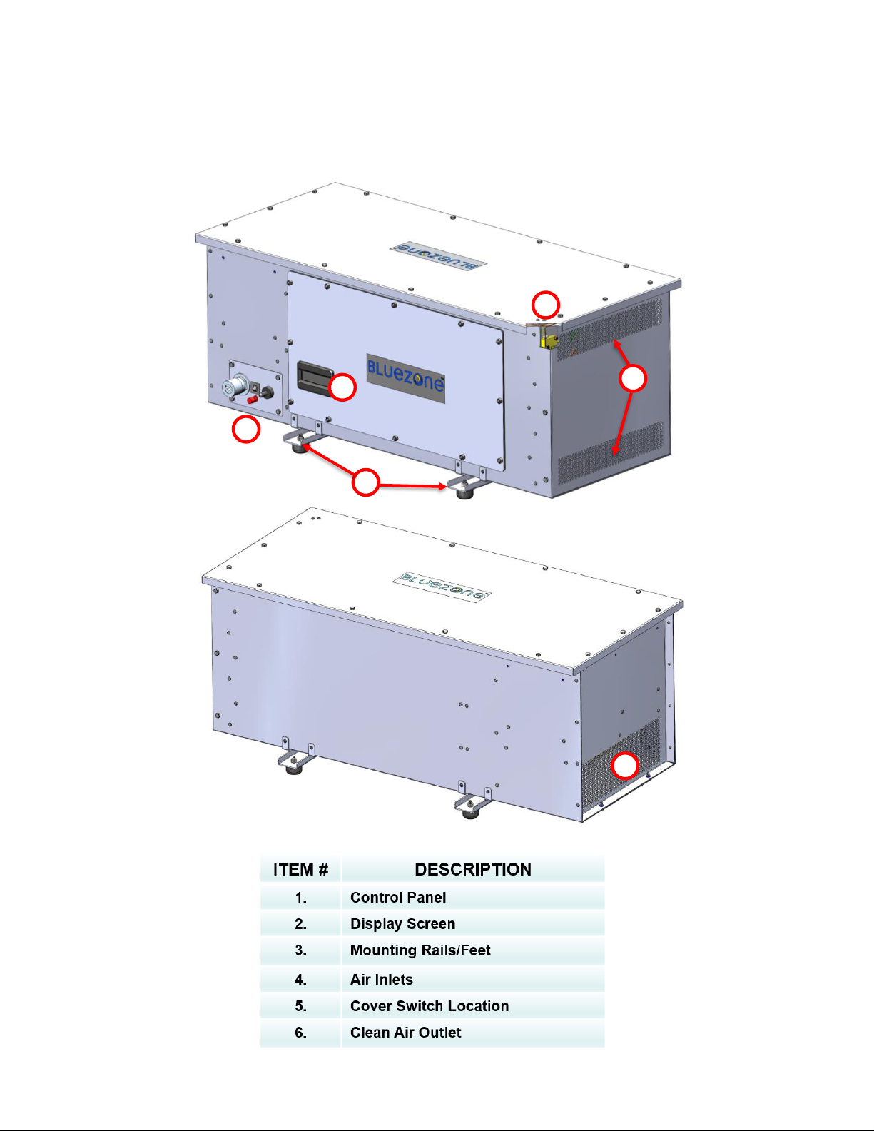
Key Components
2 6 3 5 4
1
Page 5
Document #: BZ2400-045
4
Electrical System
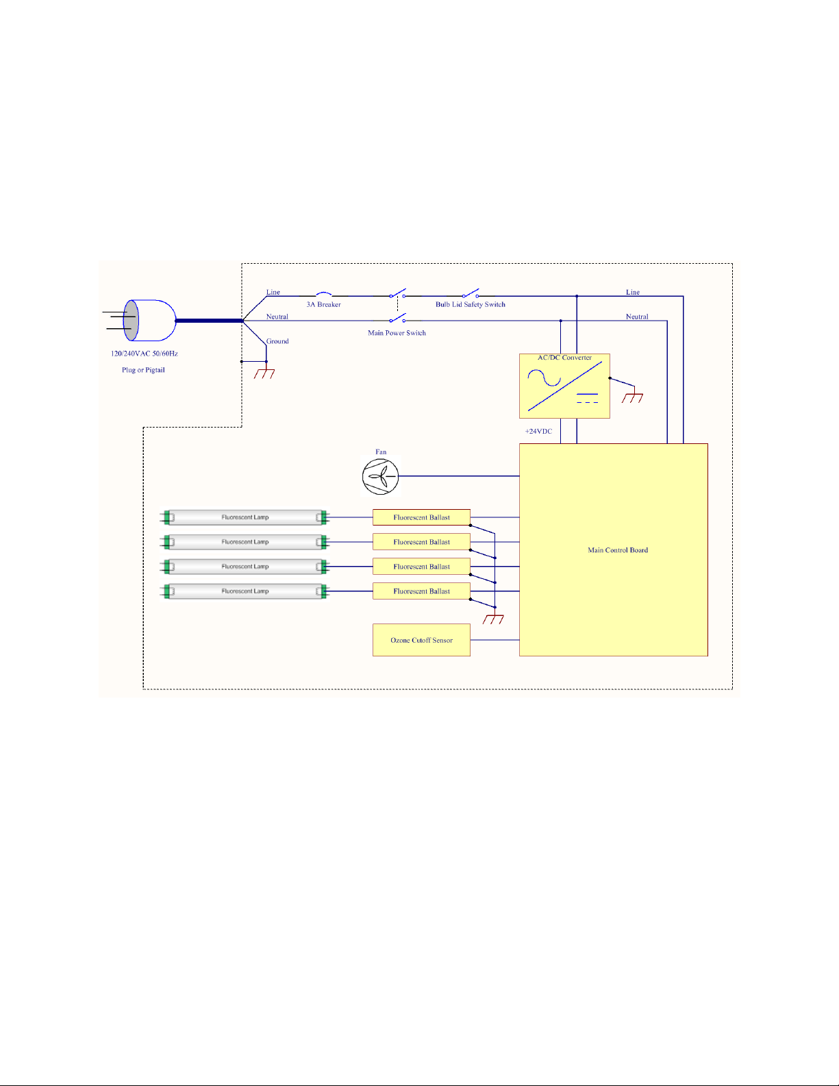
A wiring diagram of the Model 2400 is show in Figure 1.
Figure 1: Wiring Diagram of Model 2400 Unit
Page 6

Document #: BZ2400-045
5
Installation
An overview of Mechanical and Electrical
Installation instructions is contained in this
section. Details of steps to hang the Model
2400 from the ceiling or mount on a shelf
are contained in Appendix A.
Installation Guidelines
Place the Model 2400 in the room so that air
flow from the HVAC system, fans or other
air flow systems does not blow directly into
or pull air through the Model 2400 air inlet or
clean air outlet.
If the Model 2400 is installed with its air
inlets or clean air outlet directly in line with
the airflow from an HVAC outlet or fan,
ensure a minimum clearance instance of 5’
(1.5m) to avoid excessive air flow through
the unit.
Place the unit so that the control panel and
display are visible and accessible.
Each Model 2400 has the capacity to purify
up to 15,000 cubic feet (430 m3) of space.
For spaces greater than 15,000 cubic feet
(430 m3), multiple Model 2400 units will be
required.
If multiple Bluezone Model 2400 units are
being installed in a room, the following are
recommended guidelines for the placement
of the Bluezone units:
1. Distribute the units relatively evenly
throughout the space.
2. Generally spreading the locations
across the available space is good
practice.
3. Warning: Hang the units from the
ceiling, mount to the wall or on a
shelf/rack to avoid unintended bumping
of the units.
4. Units hung from the ceiling should be
hung to the level of the lights, but not
below lights to avoid blocking light to
the plants.
5. Warning: If the unit is located in an
area with foot traffic and there is a
concern that it could be bumped by
personnel, it should be labeled with
colored tape to make it more visible
and reduce the risk of collision.
6. Warning: Locate the junction
boxes for the units as close as possible
to the units to avoid the risk of hooking
the cord and pulling it out. If the
distance to the junction box is more
than 2’ (0.6 m), the cord should be tied
to the wall, rack, or ceiling to keep it
protected.
Page 7
Document #: BZ2400-045
6
Mechanical Installation
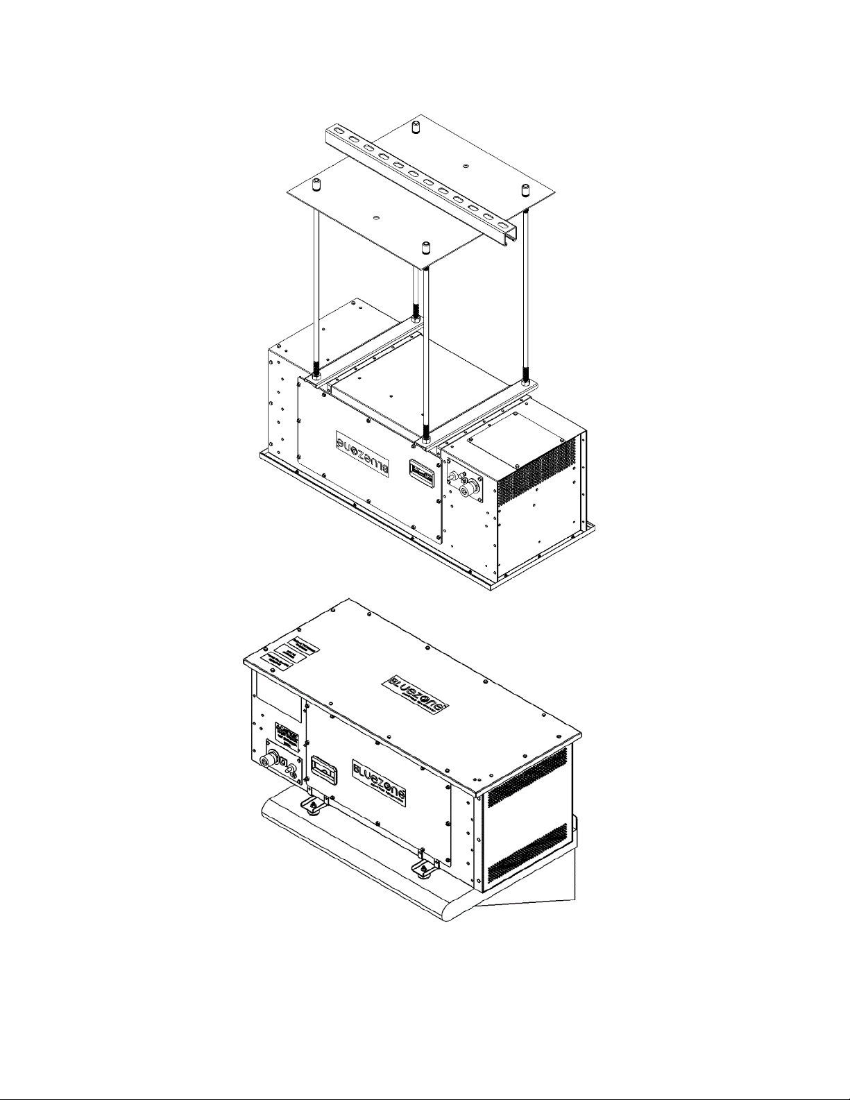
The Bluezone unit can be hung from the
ceiling or placed on a shelf. A ceiling mount
kit and a shelf mounting kit are available for
purchase.
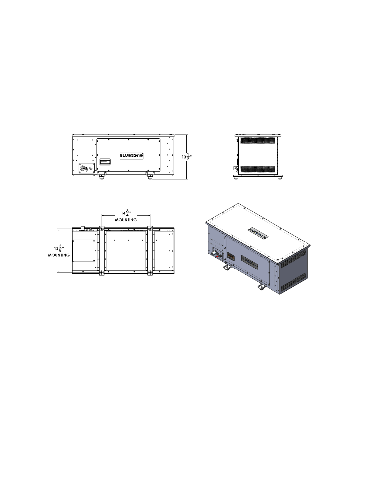
A drawing of the mounting locations on the
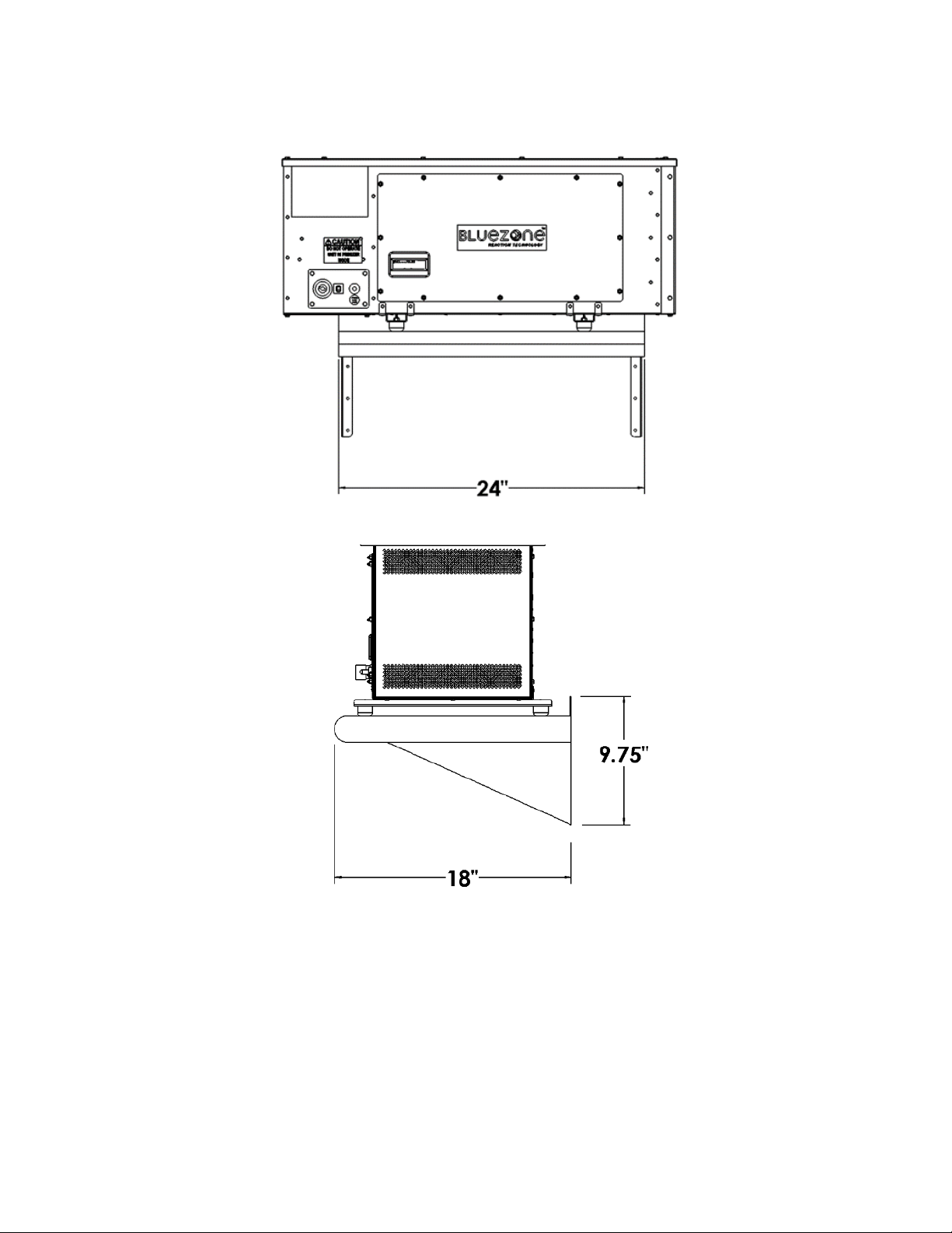
Model 2400 is provided in Figure 2.
Figure 2: Bluezone Model 2400 Mount Dimensions (units in inches)
Page 8
Document #: BZ2400-0XX
7
-
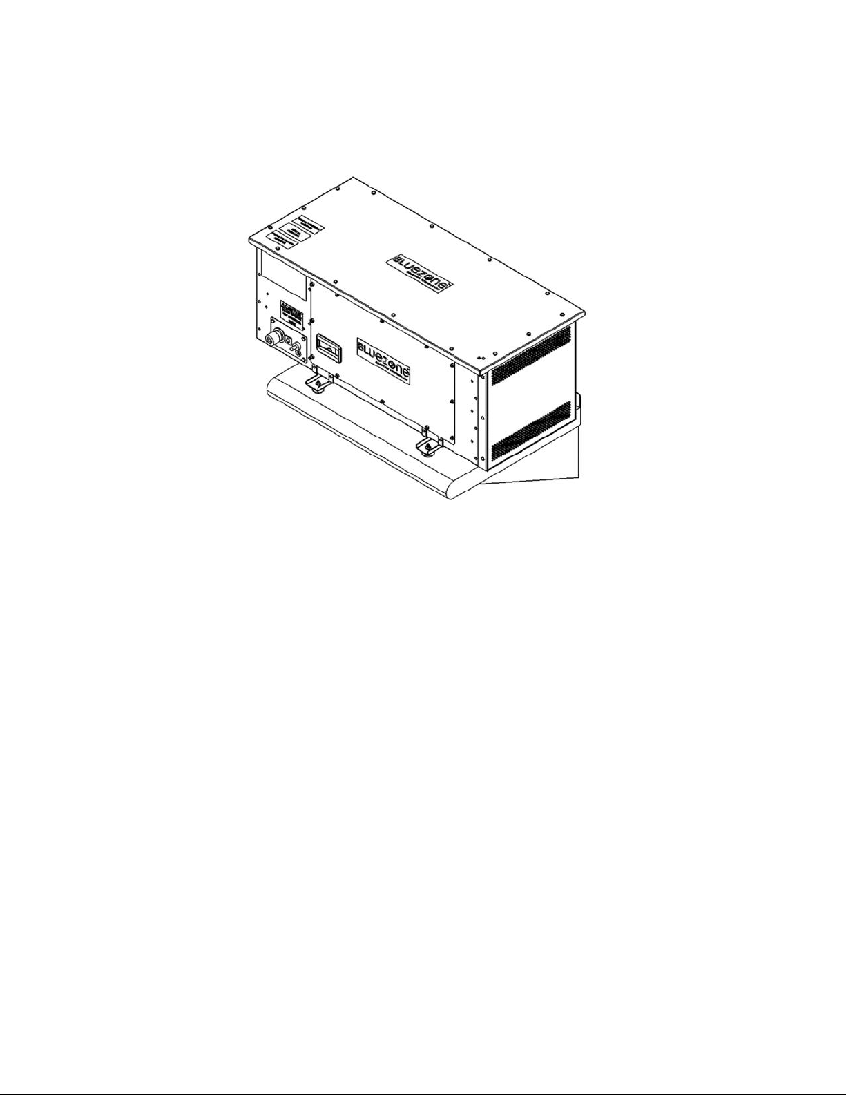
Figure 3: Illustration of the Ceiling Mount and Shelf Mount
Page 9
Document #: BZ2400-0XX
8
Electrical Installation
The Bluezone unit is equipped with a 6’ (1.8
m) power cord. The unit may be hardwired
into an AC junction box or plugged into an
appropriate AC receptacle.
Once the Model 2400 is positioned
mechanically in the space, plug or wire the
unit into the nearest un-switched electrical
outlet rated to the voltage on the unit’s
model/serial number plate.
Secure the cord.
Warning
The power cord is attached to the front of
the unit and may be caught and pulled
during activities in the space. Secure the
power cord to the shelving, wall or other
stable surface, as close to the strain relief
as possible.
Electrical Requirements
Input Voltage: 90VAC – 277VAC
Input Frequency: 50/60Hz
Input Current: 2.5A max @ 120VAC, 1.25A
max @ 240VAC
Input Power: 300W max
Installation for Pigtailed
Systems
Installation of an M2400 with a pigtail power
cable involves wiring the system into a
permanent location such as an electrical
junction box. Ensure that all local safety
regulations are adhered to when installing
the M2400.
Danger
Never install the M2400 pigtail connection
until power is removed from the site of the
connection. This may involve local safety
procedures such as lock-out/tag-out, etc.
Refer to your local site safety administrator
before proceeding.
The M2400 pigtail power cable wiring table
is shown below:
Table 2: M2400 Pigtail Power Cable Wiring
Name
Color Identification
Line
Blue
Neutral
Brown
Ground
Yellow + Green Stripe
Important
Only connect the M2400 line/neutral
connections to an appropriate power source
(120VAC/240VAC, single phase, 50/60Hz,
able to supply at least 300W continuously).
Warning
Connecting to a power source other than
one specified above may result in
destruction of the M2400 and may pose a
risk of injury. Only connect the system to an
appropriate power source.
Page 10
Document #: BZ2400-045
9
Operation
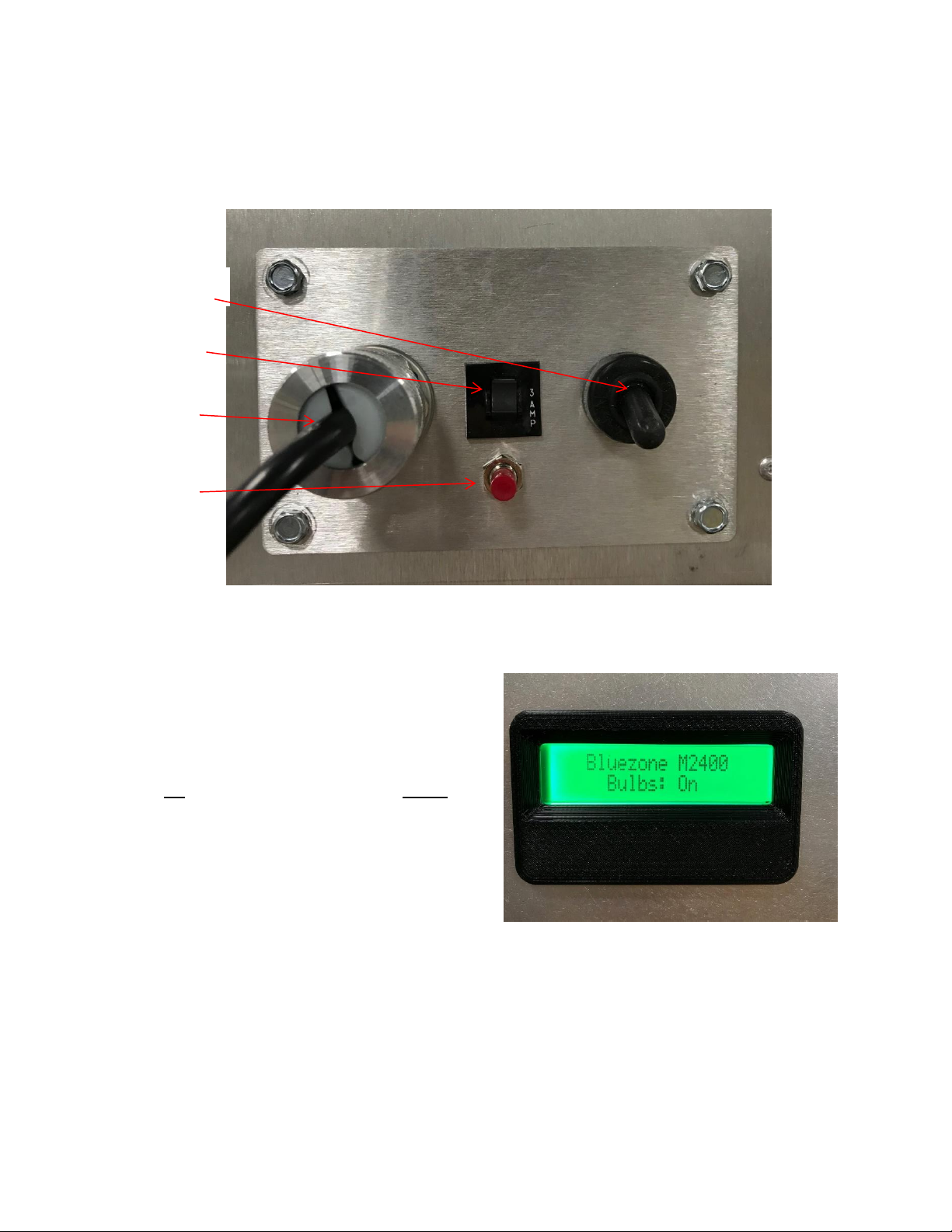
Figure 4: Control Panel on Bluezone Unit
Once the Model 2400 is mounted and wired,
it can be turned ‘On’ using the power switch
on the control panel.
In the view shown in Figure 4, pressing the
switch up is “On”. Pressing the switch down
is “Off”.
Toggle the power switch up to the “On”
position to energize the unit.
Normal Operation
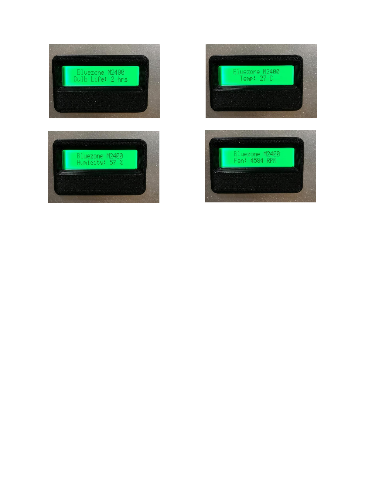
Once the Bluezone is switched “On”, the
Display Screen will indicate “Bluezone
M2400” on a green background on the top
line.
The bottom line of the display screen will
confirm bulb operation, a bulb life counter,
the temperature, humidity and fan speed.
Power Switch
Circuit Breaker
Power cord
Bulb Counter
Reset Button
Page 11
Document #: BZ2400-0XX
10
Fault Conditions and Fault
Codes
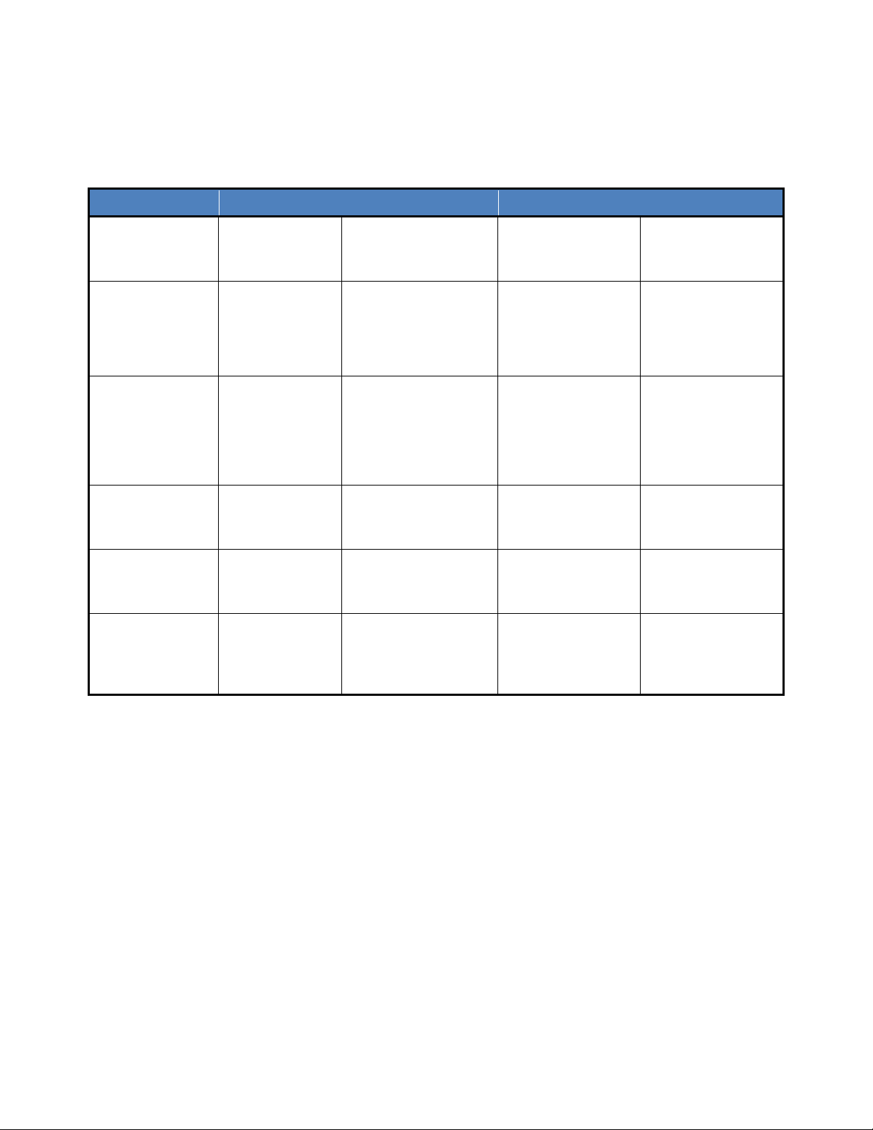
If there are issues with the operation of the
Model 2400, the onboard diagnostics will
indicate the nature of the problem.
Display Screen codes are shown in Table 3.
.
Page 12
Document #: BZ2400-0XX
11
Table 3: Display Screen Status Indicator Fault Codes
Display Color
Display Text
Fault
Operation
Action to Take
Green
Background
Bluezone M2400
Unit conditions
scrolling
System operating
properly.
Operates
None
Flashing Green
Background
Bluezone M2400
Unit conditions
scrolling
Freezing
temperatures
detected.
Unit is off and will
power up when
temperature
increases to >0C
Do not run unit in a
freezing
environment.
Yellow
Background
Contact
Bluezone
Fan not rotating, or
Humidity sensor
failure, or
Bulb counter failure
Unit automatically
powered down.
Check fan for any
visible obstructions.
Contact Bluezone
Products for
service.
Yellow
Background
Replace Bulbs
Unit conditions
scrolling
Bulb life >7,200
hours of operation.
Operates until
8,000 hours of
operation.
Check bulb counter
Order new bulbs
Red Background
Contact
Bluezone
Ozone sensor Trip
Unit automatically
powered down until
sensor resets.
Contact Bluezone
Products
Red Background
Replace Bulbs
Bulb life at 8,000
operation hours.
Unit automatically
powered down until
bulbs replaced and
counter reset.
Replace bulbs and
reset bulb life
counter.
Page 13

Document #: BZ2400-0XX
12
Diagnostics
If the Display Screen has no light or text
then the Model 2400 is not being
powered. Check the following list for
possible causes and solutions:
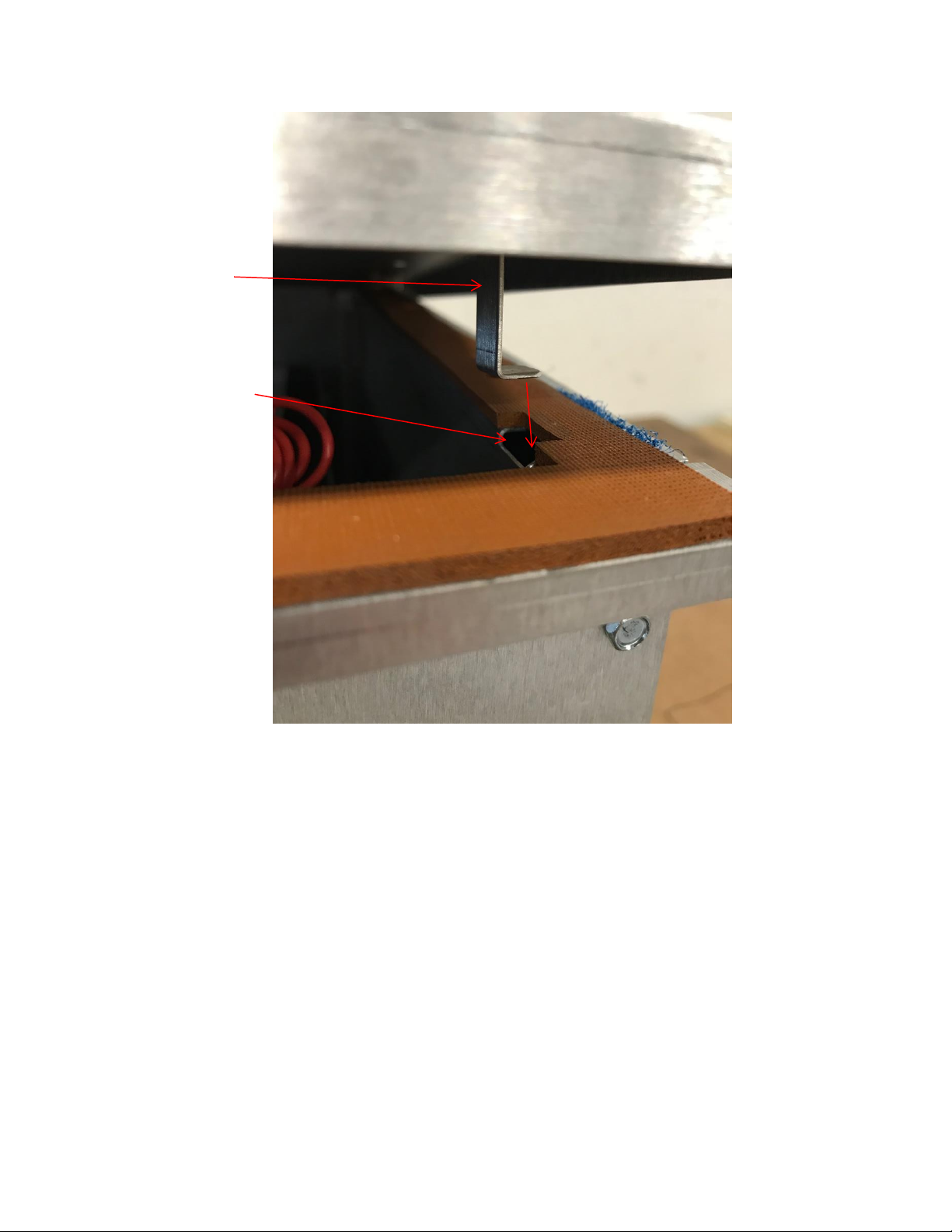
1. Make sure the cover is on and
the Cover Switch is Activated.
See Figure 5 for proper installation of
the cover switch.
Controls will not energize if cover is off
or if the cover switch is not engaged.
2. Check that unit is powered.
a. Power “Off” unit by pressing
the power switch located on
the control panel away from
the cover
b. Plug unit in.
c. Turn unit “On” by lifting the
power switch toward the
cover.
3. Restart the unit.
a. Power “Off” unit by pressing
the power switch located on
the control panel away from
the cover
b. Wait 5 seconds.
c. Turn unit “On” by lifting the
power switch toward the
cover.
d. Repeat 3 times
4. Check whether the unit’s circuit
breaker has tripped.
a. Visually check the circuit
breaker located on the
control panel. If a white strip
is visible, then the breaker
needs to be reset.
b. Power “Off” unit using the
power switch located on the
control panel.
c. Reset circuit breaker located
on the control panel by
pushing the visible indicator
back into the circuit breaker.
d. Turn unit “On” using the
power switch located on the
control panel.
The Bluezone will not turn on if the cover switch is not engaged. Make sure the cover
switch is inside the cover switch opening.
Danger
DO NOT activate the cover switch without the cover on. UV light will be emitted.
`
Page 14
Document #: BZ2400-0XX
13
Figure 5: Bluezone Cover Switch and Cover Switch Hole
Cover switch hole
Cover switch
Page 15

Document #: BZ2400-0XX
14
New Equipment Warranty
Bluezone Products, Inc. warrants that new
equipment manufactured in Bluezone’s
facilities are free of defects due to poor
materials or workmanship for a period of 1
year from the date of purchase.
Bluezone Products, Inc. warrants that the
equipment will function properly, to our
specifications and will be repaired, if
necessary, at no charge for a period of 1
year (See our warranty policy for details).
All Bluezone products have been tested by
independent labs and in several cold
storage facilities, proving the performance
as described in our literature. Our air
purification equipment is a powerful tool to
help purify your environment yet, we cannot
guaranty that under your operating
conditions and procedures, the results will
be the same as experienced by other users.
If you are not satisfied with the purchase or
the operation of our equipment, it can be
returned if the equipment was un-used and
was returned within 14 days. The customer
will be charged return freight and an
additional 10% of the purchase price as
a restocking fee.
Bulb Disposal
Bulbs contain a small amount of mercury
Bulb handling should be similar to that used for fluorescent or compact fluorescent bulbs.
Bluezone Products, Inc. recommends that you take advantage of available local recycling
options for CFLs. Lists of recycling facilities are available at: www.earth911.org.
Dispose of according to local, state or federal laws.
Page 16

Document #: BZ2400-0XX
15
Service
BULBS NEED TO BE REPLACED AFTER 8,000 HOURS OF USE. BULB KITS MUST BE
PURCHASED DIRECTLY FROM BLUEZONE PRODUCTS AS THEY ARE PROPRIETARY
BULBS.
Bulbs must be replaced at 8,000 hours of
operation. The display screen reads
accumulated bulb hours throughout the
unit’s operation. At 7,200 hours the display
screen will turn yellow and read “Replace
Bulbs.” The bulbs should be ordered and
replaced immediately. At 8,000 hours, the
display screen will turn red and the unit will
automatically be powered OFF until bulbs
are replaced. Note: the fan will run on low
speed, but the bulbs will turn off.
After bulbs are replaced, the bulb counter
needs to be reset. To reset the bulb counter
please follow the steps below.
1) Press and hold the red bulb counter
reset button for 5 seconds. The
display screen will read “Hold: reset
counter” during the 5 second hold.
2) After holding for 5 seconds, press
the bulb counter reset button again
to finalize reset. The display screen
will read “push to confirm” after the 5
second hold.
A bulb replacement kit and instructions can
be ordered from Bluezone Products, Inc.
Please call (781) 937-0202 or email
[email protected] for ordering
information.
IMPORTANT: Each bulb kit satisfies
replacement parts for 1 unit. The four bulbs
in each replacement kit cannot be replaced
with bulbs purchased from anywhere, but
Bluezone Products or an Authorized
Partner. Installation of the incorrect bulbs
results in a voided warranty. Purchase of
bulbs from an outside vendor results in a
voided warranty. Bluezone will not operate
correctly with bulbs purchased from outside
vendors.
Service Kit includes:
• (4) U-shaped bulbs
• (2) Nitrile gloves
• Exta 5/16 cover screws
Additional tools needed:
• 5/16 socket
Page 17

Document #: BZ2400-045
16
Instructions for Bulb Replacement:
1) Toggle the power switch located on
the unit’s control panel to OFF.
2) Wait 15 minutes for the ozone to
clear from the Bluezone reaction
zone.
3) WARNING: Before proceeding
to next step, unplug the unit from it’s
power supply.
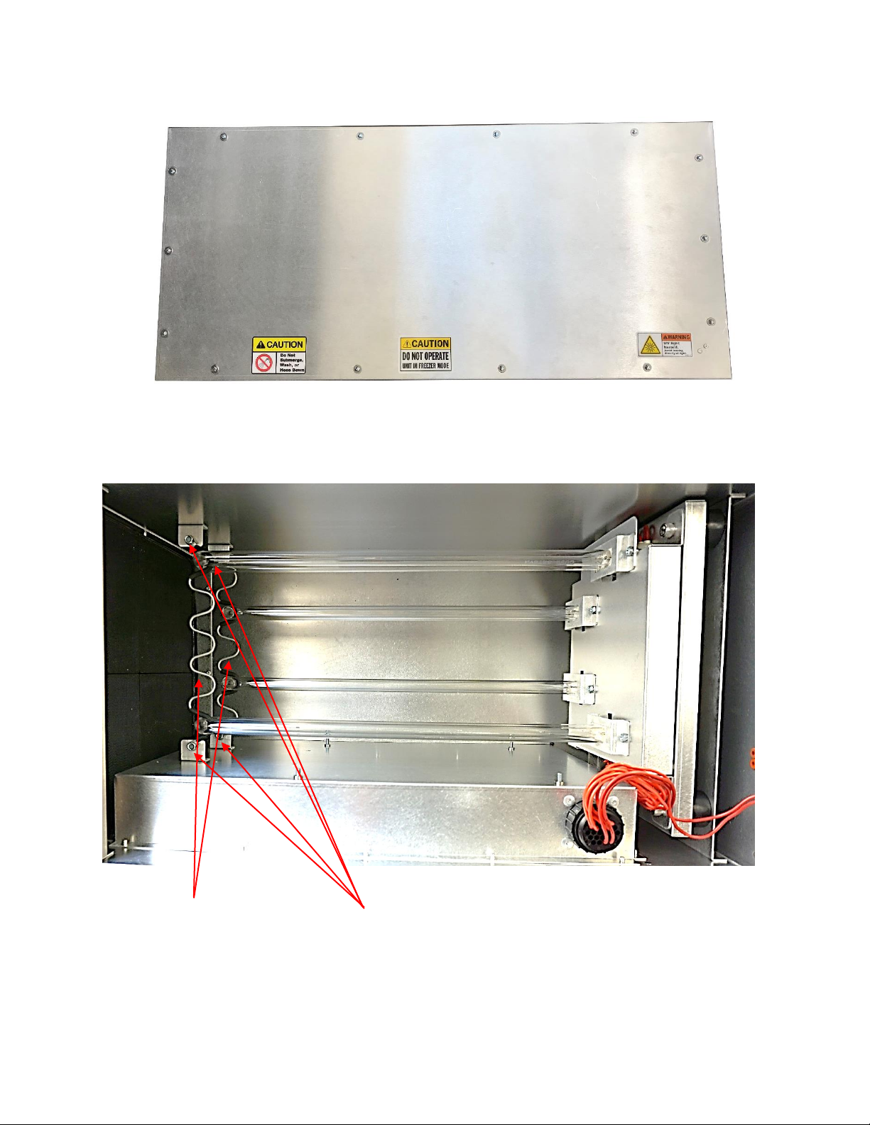
4) Use the 5/16 socket to unscrew the
14 screws on the cover, see Figure 6
below.
5) Slowly, remove the cover and place it
on a flat surface.
6) Use the gloves provided to remove
and replace the bulbs. This will
prevent oil on your hand from
damaging the new bulbs.
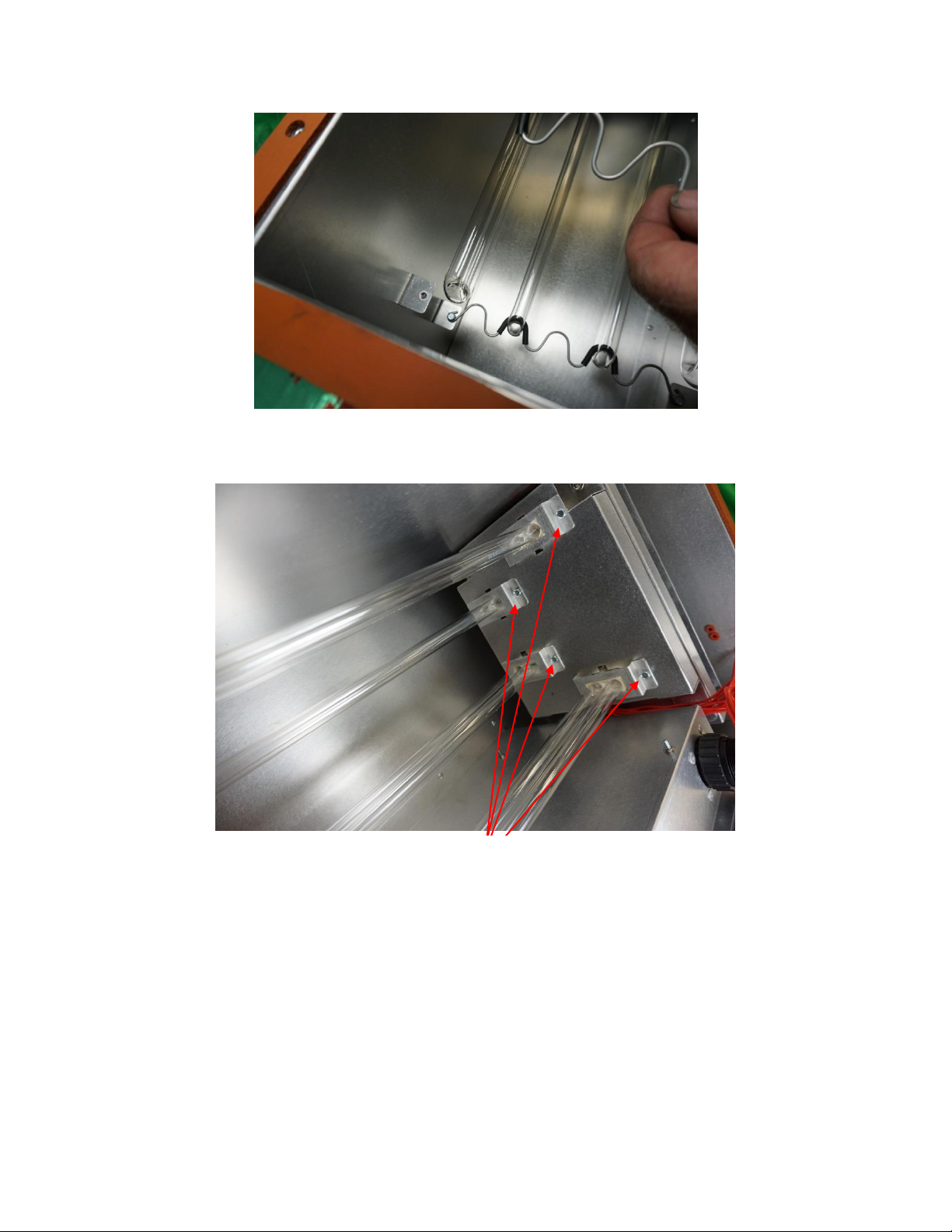
7) Unscrew the 5/16 screws on Bulb
Support Wires. See Figure 7 below.
8) Carefully remove Bulb Support Wires
and place aside. See Figure 8 below.
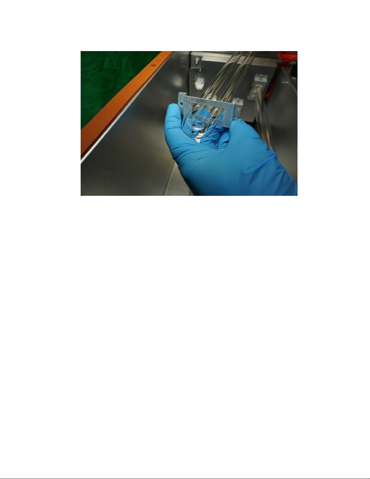
9) Unscrew 5/16 screws on Bulb Clips.
See Figure 9 below.
10) Remove the old bulbs (Note: pull on
them at the ceramic base, not on the
glass) Put the bulbs to the side for
disposal.
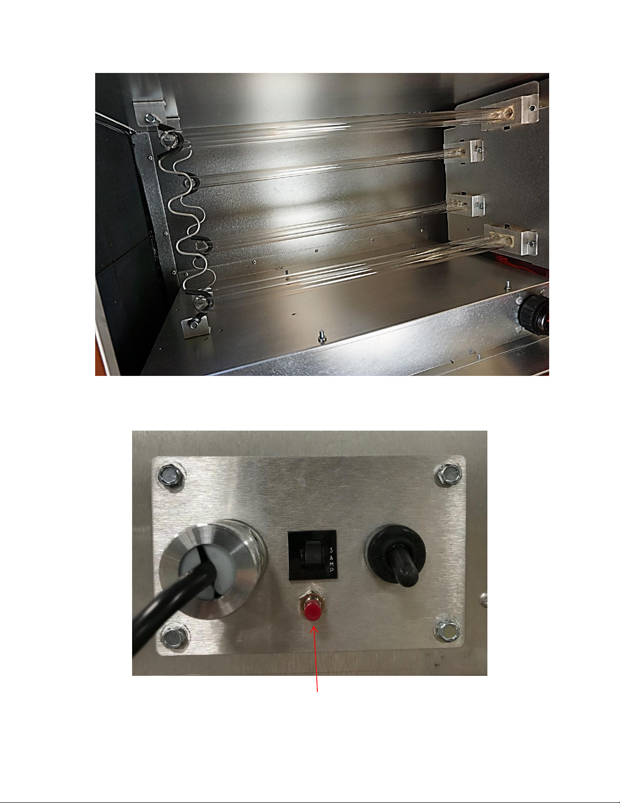
11) Carefully remove Bulb Clips and
place aside. See Figure 10 below.
12) Hold replacement bulbs by the
ceramic end and push the pins into
the slots in the receptacle.
They need to be pushed in
until a “click” is heard and
felt.
13) Put Bulb Clips over new bulbs and
use screws to tighten Bulb Clips in
place.
14) Thread Bulb Support Wires through
bulbs and use screws to tighten Bulb
Support Wires in place.
15) Tighten cover back onto the unit.
16) Dispose of used bulbs, according to
standard practice for florescent bulbs.
IMPORTANT
17) Press and hold the red bulb counter
reset button for 5 seconds. The display
screen will read “Hold: reset counter”
during the 5 second hold. See Figure
12.
18) After holding for 5 seconds, press the
bulb counter reset button again to
finalize reset. The display screen will
read “push to confirm” after the 5
second hold.
Estimated total bulb replacement time:
approximately 30 minutes per unit.
Page 18
Document #: BZ2400-045
17
Figure 6: Unscrew 14 Screws on Bluezone M2400 Cover
Figure 7: Remove 5/16 Screws Holding Bulb Support Wires
5/16 screws to be removed
Bulb Support Wires to be
removed
Page 19
Document #: BZ2400-0XX
18
Figure 8: Remove Bulb Support Wires and Place Aside
Figure 9: Remove 5/16 Screws on Bulb Support Clips
5/16 screws to remove
Page 20
Document #: BZ2400-0XX
19
Figure 10: Carefully Slide off Bulb Clips using Nitrile Gloves
Page 21
Document #: BZ2400-0XX
20
Figure 11: Completed Bulb Assembly
Figure 12: Bulb counter reset button
Page 22

Document #: BZ2400-0XX
21
Appendix A:
Bluezone Unistrut Channel Mount Installation
Bluezone Shelf Mount Installation
Page 23
Document #: BZ2400-0XX
22
Bluezone Unistrut® Channel Mount Installation
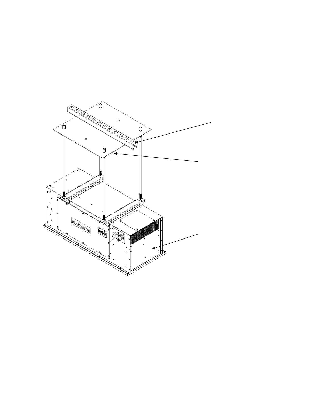
The Bluezone Model 2400 can be mounted to the ceiling using existing your facility’s existing
Unistrut® metal framing system, and the Bluezone Mounting Kit as shown below.
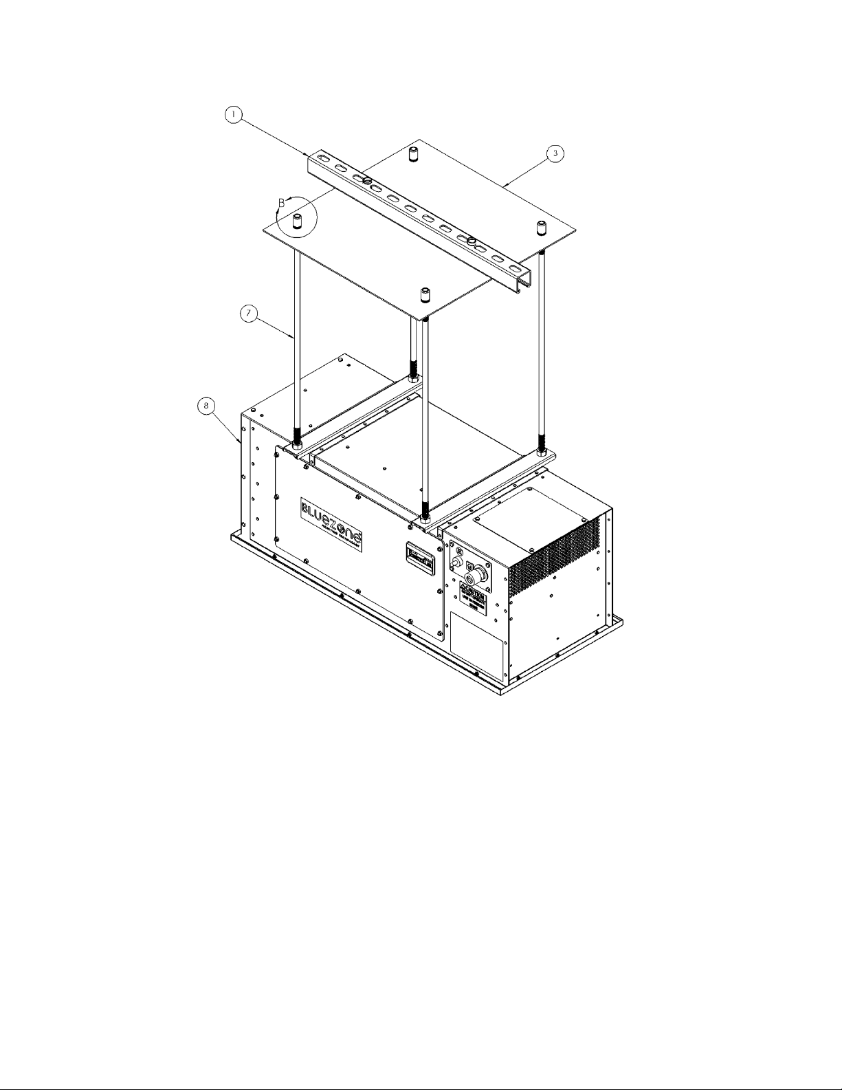
EXISTING UNISTRUT IN
FACILITY
BLUEZONE UNIT
MOUNTING KIT
Page 24
Document #: BZ2400-0XX
23
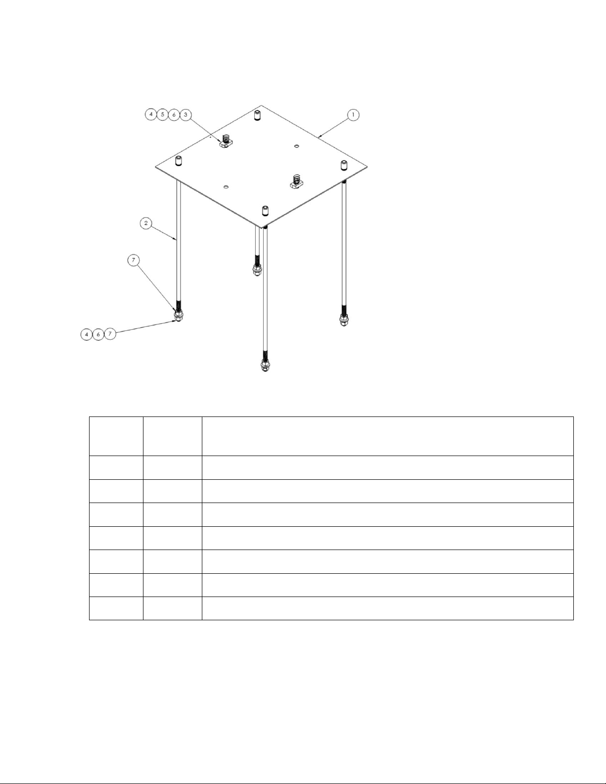
Mounting Kit
Mounting Kit Materials
Item
Number
Number
of Pieces
Description
1
1
Steel mounting plate, 12 AWG, 18” x 18” with rivet nuts installed
2
4
Threaded rod ½” – 2-foot standard size, custom lengths available
3
2
Strut channel nut with spring, ½”
4
6
Washer ,½”
5
2
Hex head screw, ½”
6
6
Split lock washer, ½”
7
8
Hex nuts, ½”
Not included in kit...
• Unistrut channel
• Bluezone unit
Page 25
Document #: BZ2400-0XX
24
Instructions
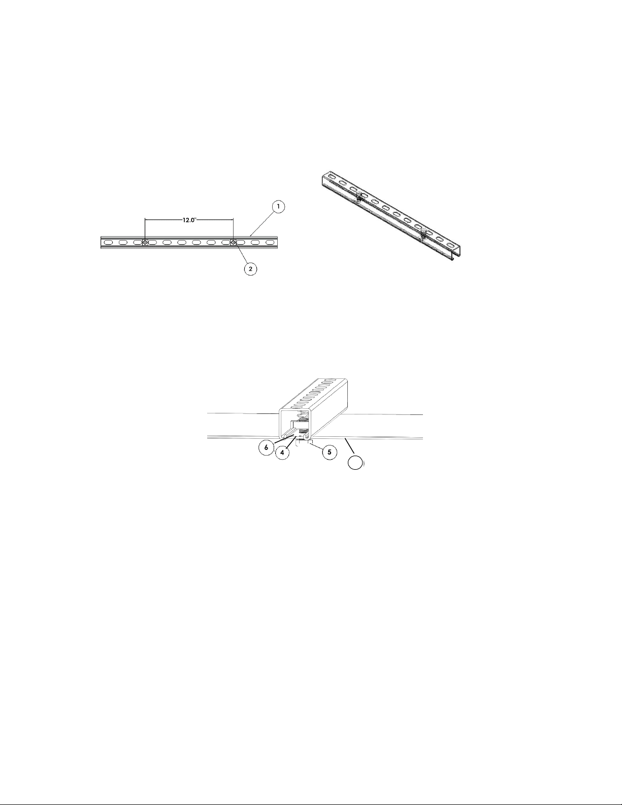
1. Insert 2 channel nuts 12” apart in Unistrut® channel. Please note Unistrut channel is
existing in client facility.
2. Attach mounting plate to Unistrut channel by inserting hex screws with washer and
lock washer into channel nuts.
1
Page 26
Document #: BZ2400-0XX
25
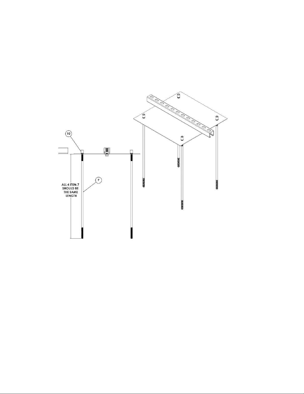
3. Insert (4) threaded rods into rivet nuts. Threaded rods should hang Bluezone at the
level of the grow lights. Ensure all threaded rods are completely inserted.
Custom
lengths
available
Page 27
Document #: BZ2400-0XX
26
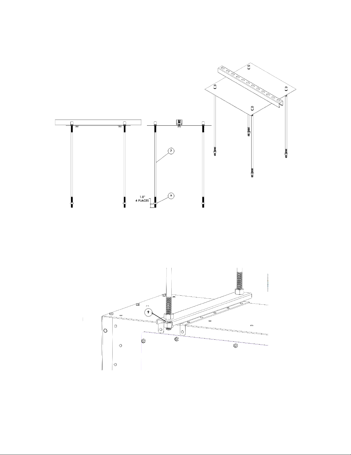
4. Attach ½” hex nuts onto all threaded rods, ~1” up threaded rod.
5. Secure Bluezone to threaded rods using lock washer, washer and hex nut. This step
requires two workers… one to hold the Bluezone and one to attach hardware.
Page 28
Document #: BZ2400-0XX
27
Figure 12: Completed Assembly
Page 29
Document #: BZ2400-0XX
28
Shelf Mount
Materials
Included in kit…
• Wall mount shelf
• Mounting brackets
• Installation screws and anchors
Page 30
Document #: BZ2400-0XX
29
Page 31

Document #: BZ2400-0XX
30
Vendor Contact Information:
Technical Support is provided by:
Bluezone Products, Inc.
225 Wildwood Ave
Woburn, MA 01801
(781) 937-0202
 Loading...