


F-2000
MODEL RT
INSTRUCTION MANUAL
R
Blue-White
Industries, Ltd.
Find Quality Products Online at: sales@GlobalTestSupply.com
www.GlobalTestSupply.com

F-2000
Page 2
TABLE OF CONTENTS
Section Heading Page
1.0 Features 3
2.0 Applications 3
3.0 Specifications 3
3.1 Physical 3
3.2 Dimensional Drawing 4
3.3 Temperature vs. Pressure Graph 4
4.0 Flow ranges 5
5.0 Mounting Options 6
6.0 Electrical Wiring Connections 8
6.1 Enclosure Knock-Out Instructions 8
6.2 Optional Circuit Board Installation 8
6.3 Model RT Circuit Board Wiring 9
6.4 Model FHXX and FCXX Sensor Wiring 10
7.0 Operation 11
7.1 Theory of operation 11
7.2 Model RT Operation 11
7.2.1 Model RT Applications 11
7.2.2 Model RT Features 12
7.2.3 How to Determine Calibration Constants 12
7.2.4 Programming the Model RT 15
7.2.5 Calibration Constants 16
7.3 Programming flow chart 18
8.0 Maintenance 19
8.1 Troubleshooting 19
F-2000 parts list 20
. . . F-2000 exploded view 21
Find Quality Products Online at: sales@GlobalTestSupply.com
www.GlobalTestSupply.com

Page 3
1.0 FEATURES
!
Battery powered rate and total
!
Weather resistant enclosure (NEMA 4X)
F-2000
!
Extended battery life mode
(screen blanks after 30 seconds)
!
Easy to read, eight digit LCD display
!
Installs quickly on existing pipe
!
Factory programmed
!
Field programmable front panel push buttons
!
No pressure drop
2.0 APPLICATIONS
Model RT
!
Measure and display the rate of flow
!
Measure and display the total flow
Model AO
!
Measure and display the rate of flow
!
Measure and display the total flow
!
Control external devices with 4-20mA
control signal
!
Control external devices with 0-10VDC
control signal
!
Corrosion resistant PVDF sensor
!
Corrosion resistant ABS enclosure
!
High accuracy
!
Extended flow range
!
Front panel security lockout
!
Minimal maintenance required
Model PC
!
Measure and display the rate of flow
!
Measure and display the total flow
!
Maintain a flow rate range alarm
!
Trigger a high flow rate alarm
!
Trigger a low flow rate alarm
!
Manually controlled batch processing
!
Timed auto-reset batch processing
!
Proportional flow chemical pump process
control
3.0 SPECIFICATIONS
3.1 Physical
Maximum Working Pressure ...... ............300 psig (20.7 bar)
Maximum fluid temperature........ ............200 F (93 C) - saddle and sensor only
200 F (93 C) - polypropylene and PVDF inline units
140 F (60 C) - molded PVC tee units
140 F (60 C) - when mounted on PVC pipe
Ambient temperature range........ ............32 F (0 C) to 110 F (43 C)
Enclosure ......... ............ ............ ............NEMA 4X (acceptable for outdoor use)
NOTE: Protect the LCD display from direct sunlight.
Sensor Accuracy ........... ............ ............±1% of full scale reading
Repeatability..... ............ ............ ............±1% of full scale reading
Power requirements ...... ............ ............15 VDC Nominal (12 - 24 VDC Absolute - DO NOT EXCEED 24.0 VDC)
Model RT units only....... ............Four standard AA alkaline batteries or 12-24VDC Plug in transformer
(Battery life expectancy 1 year minimum)
All units ............ ............ ............12-24VDC (plug-in transformer supplied)
Model AO analog output board... ............Linear, Non-isolated, powered loop. 250 ohm max for 4-20 ma / 500
Model PC Process control board ............Relay SPDT, NO/NC
Maximum switching load 8 amps @ 115 VAC, 220 VAC, 230 VAC
Maximum fluid debris size .......... ............0.020” diameter
o o
o o
o o
o o
o o o o
ohms minimum for 0-10 VDC
7 amps @ 30 VDC (resistive load)
Find Quality Products Online at: sales@GlobalTestSupply.com
www.GlobalTestSupply.com

F-2000
Page 4
3.2 Dimensional Drawing
4.00 in.
(101.6 mm)
BLUE-WHITE INDUSTRIES
4.00 in.
(101.6 mm)
8888.8888
MA BATCH # RATE TOTAL SETPOINT
ENTER
Flow Monitoring System
3.3 Temperature vs. Pressure
Temperature
200°F (93.3°C)
190°F (87.8°C)
180°F (82.2°C)
170°F (76.7°C)
160°F (71.1°C)
150°F (65.6°C)
140°F (60°C)
130°F (54.4°C)
120°F (48.9°C)
110°F (43.3°C)
100°F (37.8°C)
90°F (32.2°C)
80°F (26.7°C)
70°F (21.1°C)
Note: Pressure and temperature limits are inversely proportional.
0 (0) 60 (4.1) 120 (8.3) 180 (12.4) 240 (16.5)
PSIg (BAR)
When mounted on Polypropylene and PVDF inline units
When mounted on Molded PVC Tee or PVC pipe units
F-2000
CLEAR
SETPOINT
3.25 in.
(82.55 mm)
®
CLEAR
TOTAL
Fig. 1
300 (20.7)
Fig. 2
4.0 FLOW RANGES
Note: Due to increased wear on the paddle and axle, continuous operation at the upper 25% of the
flow range is not recommended
METRIC PIPES
SADDLES - Standard Flow [Min - Max]
Pipe Size
50 MM - PN 10 & PN 16
63 MM - PN 10 & PN 16
90 MM - PN 10 & PN 16
110 MM - PN 10 & PN 16
160 MM - PN 10 & PN 16
200 MM - PN 10 & PN 16
160 MM - PN 10
200 MM - PN 10
Find Quality Products Online at: sales@GlobalTestSupply.com
LPM 1
110 - 1100
230 - 2300
350 - 3500
720 - 7200
1150 - 11500
1700 - 17000
2700 - 27000
LPH 1
4200 - 4200070.0 - 700.0
6600 - 66000
13800 - 138000
21000 - 210000
43000 - 430000
70000 - 700000
100000 - 1000000
170000 - 1700000
M3H 1
4.20 - 42.00
6.60 - 66.00
13.8 - 138.0
21.0 - 210.0
43.0 - 430.0
70.0 - 700.0
100 - 1000
170 - 1700
www.GlobalTestSupply.com

Page 5
IPS PIPES
MOLDED INLINE BODIES - min - max operating flow range
Pipe Size
3/8”
3/8”
1/2”
1/2”
3/4”
3/4”
1”
1”
1-1/2”
1-1/2”
1-1/2”
2”
2”
2”
2”
RANGE#
1
2
1
2
1
2
1
2
1
2
3
1
2
3
4
MACHINED INLINE BODIES - min - max operating flow range
Pipe Size
3/8”
3/8”
1/2”
1/2”
3/4”
3/4”
1”
1”
1-1/2” 15.0 - 150.0 900 - 9000 21500 - 215000
1-1/2”
1-1/2”
1-1/2” 2.00 - 20.00 120 - 1200 2800 - 28000
1-1/2” 1.00 - 10.00 60.0 - 600.0 1440 - 14400
2” 1800 - 1800030.0 - 300.0 43000 - 430000
2” 15.0 - 150.0 900 - 9000 21500 - 215000
2”
2”
2”
2” 2.00 - 20.00 120 - 1200 2800 - 28000
RANGE#
1
2
1
2
1
2
1
2
1
2
3
4
5
1
2
3
4
5
6
GPM
2.00 - 20.00
.500 - 5.000
3.00 - 30.00
.800 - 8.000
5.00 - 50.00
2.00 - 20.00
10.0 - 100.0
4.00 - 40.00
6.00 - 60.00
10.0 - 100.0
20.0 - 200.0
GPM
2.00 - 20.00
.500 - 5.000
4.00 - 40.00
.800 - 8.000
6.00 - 60.00
2.00 - 20.00
10.0 - 100.0
10.0 - 100.0
6.00 - 60.00
4.00 - 40.00
GPH
48.0 - 480.0.800 - 8.000
20.0 - 200.0.400 - 4.000
120 - 1200
30.00 - 300.0
180 - 1800
48.0 - 480.0
300 - 3000
120 - 1200
240 - 24004.00 - 40.00
360 - 36006.00 - 60.00
600 - 6000
240 - 2400
360 - 3600
1200 - 12000
GPH
48.0 - 480.0.800 - 8.000
20.0 - 200.0.400 - 4.000
120 - 1200
30.00 - 300.0
240 - 2400
48.0 - 480.0
360 - 3600
120 - 1200
600 - 6000 14400 - 144000
360 - 36006.00 - 60.00
240 - 2400
1100 - 11000
2800 - 28000
4320 - 43200
1100 - 11000
7200 - 72000
2800 - 28000
5700 - 57000
8600 - 86000
14400 - 144000
5700 - 57000
8600 - 86000
14400 -144000600 - 6000
28800 - 288000
1100 - 11000
2800 - 28000
5700 - 57000
1100 - 11000
8600 - 86000
2800 - 28000
8600 - 86000
14400 -144000600 - 6000
8600 - 86000360 - 3600
5700 - 57000
GPD
550 - 5500
700 - 7000
GPD
550 - 5500
700 - 7000
F-2000
LPM
7.00 - 70.00
2.00 - 20.00
11.0 - 110.0
3.00 - 30.00
20.0 - 200.0
7.00 - 70.00
40.0 - 400.0
15.0 - 150.0
25.0 - 250.0
40.0 - 400.0
70.0 - 700.0
LPM
7.00 - 70.00
2.00 - 20.00
15.0 - 150.0
3.00 - 30.00
25.0 - 250.0
7.00 - 70.00
60.0 - 600.0 3600 - 36000 3.60 - 36.00
40.0 - 400.0
7.00 - 70.00 420 - 4200 0.420 - 4.200
4.00 - 40.00 240 - 2400 0.240 - 2.400
60.0 - 600.0 3600 - 36000 3.60 - 36.00
40.0 - 400.0
25.0 - 250.0
15.0 - 150.0
7.00 - 70.00 420 - 4200 0.420 - 4.200
LPH
180 - 18003.00 - 30.00
60.0 - 600.01.00 - 10.00
420 - 4200
120 - 1200
660 - 6600
180 - 1800
1200 - 12000
420 - 4200
900 - 900015.0 - 150.0
1500 - 1500025.0 - 250.0
2400 - 24000
900 - 9000
1500 - 15000
2400 - 24000
4200 - 42000
LPH
180 - 18003.00 - 30.00
60.0 - 600.01.00 - 10.00
420 - 4200
120 - 1200
900 - 9000
180 - 1800
1500 - 15000
420 - 4200
2400 - 24000
1500 - 1500025.0 - 250.0
6000 - 60000100 - 1000 6.00 - 60.00
2400 - 24000
1500 - 15000
900 - 9000
M3H
0.180 - 1.800
0.060 - 0.600
0.420 - 4.200
0.120 - 1.200
0.660 - 6.600
0.180 - 1.800
1.20 - 12.00
0.420 - 4.200
0.900 - 9.000
1.50 - 15.00
2.40 - 24.00
0.900 - 9.000
1.50 - 15.00
2.40 - 24.00
4.20 - 42.00
M3H
0.180 - 1.800
0.060 - 0.600
0.420 - 4.200
0.120 - 1.200
0.900 - 9.000
0.180 - 1.800
1.50 - 15.00
0.420 - 4.200
2.40 - 24.00
1.50 - 15.00
2.40 - 24.00
1.50 - 15.00
0.900 - 9.000
SADDLES - Standard Flow [Min - Max]
Pipe Size
1-1/2” IPS
2.0” IPS
3.0” IPS
4.0” IPS
6.0” IPS
8.0” IPS
10.0” IPS
12.0” IPS
GPM = Gallons Per Minute LPM = Litters Per Minute OZM = Ounces Per Minute GPH = Gallons Per Hour
LPH = Litters Per Hour M3H = Cubic Meters per Hour GPD = Gallons Per Day LPD = Litters Per Day
Find Quality Products Online at: sales@GlobalTestSupply.com
GPM 1
15.0 - 150.0
30.0 - 300.0
60.0 - 600.0
100 - 1000
250 - 2500
400 - 4000
600 - 6000
800 - 8000
GPH 1
900 - 9000
1800 - 18000
3600 - 36000
6000 - 60000
15000 - 150000
24000 - 240000
36000 - 360000
48000 - 480000
GPD 1
21500 - 215000
43000 - 430000
86500 - 865000
144000 - 1440000
360000 - 3600000
575000 - 5750000
865000 - 8650000
1150000 - 11500000
LPM 1
60.0 - 600.0
100 - 1000
250 - 2500
400 - 4000
900 - 9000
1500 - 15000
2200 - 22000
3000 - 30000
www.GlobalTestSupply.com
LPH 1
3600 - 36000
6000 - 60000
15000 - 150000
24000 - 240000
54000 - 540000
90000 - 900000
132000 - 1320000
180000 - 1800000
M3H 1
3.60 - 36.00
6.00 - 60.00
15.0 - 150.0
24.0 - 240.0
54.0 - 540.0
90.0 - 900.0
132 - 1320
180 - 1800

F-2000
5.0 Mounting Options
Rotating Display
Page 6
Step 1: Remove Two Screws
Angle Mount on Horizontal Pipe
Step 2: Rotate 90°
Recommended
Vertical
Step 3: Re-attach Screws
Fig. 6
45° Acceptable45° Acceptable
Panel Mount
PANEL
F-2000
HEX NUTS
BRACKET
STUDS
Fig. 8
WASHERS
CAP PLUG
3.622 ±
(92.0 ±
.032
.000
.80
.00
Fig. 7
in.
mm)
Fig. 9
Find Quality Products Online at: sales@GlobalTestSupply.com
www.GlobalTestSupply.com

Page 7
Optional Pipe and Wall Mount Adapter Kit
F-2000
Screw
Wall Mount
Pipe Mount
®
BLUE-WHITE INDUSTRIES
F-2000
ENTER
CLEAR
CLEAR
SETPOINT
TOTAL
Flow Monitoring System
Display
Module
Fig. 10
Display
Module
Wire to
Sensor
Clamp
Mounting
Base
Cap
Plug
Mounting
Base
Wall
Wall
Screw
Pipe
®
BLUE-WHITE INDUSTRIES
F-2000
ENTER
CLEAR
CLEAR
SETPOINT
TOTAL
Flow Monitoring System
Ordering Information
Kit Number
71000-301
71000-302
71000-303
71000-304
71000-305
71000-306
71000-307
Fig. 11
Sensor
Decription
Wall Mount Kit
Pipe Mount Kit for 1-1/2” pipe
Pipe Mount Kit for 2” pipe
Pipe Mount Kit for 3” pipe
Pipe Mount Kit for 4” pipe
Pipe Mount Kit for 6” pipe
Pipe Mount Kit for 8” pipe
Wire to
Cap
Screw
Plug
71000-414 Pipe Mount Kit for 10” pipe
71000-415 Pipe Mount Kit for 12” pipe
Find Quality Products Online at: sales@GlobalTestSupply.com
www.GlobalTestSupply.com

F-2000
6.0 F-2000 Electrical Wiring Connections
6.1 Enclosure knock-out Instructions
Option A: Conduit Connection
1. Remove the red cap plug.
2. Install your pipe fitting (1/2 - 14 NPT male
end).
Page 8
Option A: 1 / 2-14 MPT
Red Cap Plug
(for pipe fitting)
Option B: Liquid-Tight Connections
Internal View
1. Remove knock-out(s) using a screwdriver.
2. Trim edge(s) with a knife and remove sharp
edges.
3. Install the provided liquid-tight connector(s).
Option B: 3/4 DIA.
Knock-out
(large liquid-tight connector)
Option B: 1/2 DIA.
Knock-out
(small liquid-tight connector)
Notes:
For the large liquid-tight connector (3/4” knock-out), the acceptable cable diameter is between .200 - .394 in (5.1 -
10.0 mm).
For the small liquid-tight connector (1/2” knock-out), the acceptable cable diameter is between .118 - .255 in (3.0 -
6.5 mm).
6.2 Optional Circuit Board Installation
CAUTION: DISCONNECT POWER
SOURCE BEFORE SERVICING.
F-2000-PC
1. Carefully align optional board’s Pin
Header with the Pin Header socket
located on the main circuit board.
F-2000
2. Press firmly into place.
Enclosure
Cover
3. Secure the board with the two screws
provided.
Find Quality Products Online at: sales@GlobalTestSupply.com
www.GlobalTestSupply.com
(OPTIONAL BOARD)
N.C.
N.O.
C
F-2000-RT
(MAIN BOARD)
F-2000-AO
(OPTIONAL
BOARD)

Page 9
6.3 Model RT Circuit Board Wiring
CAUTION: DISCONNECT POWER SOURCE BEFORE SERVICING.
Jumper Configuration
F-2000
Jumpers
J1 Installed
J1 Left Open
J2 Installed
J2 Left Open
J3 Installed and J4 Left Open
J3 Left Open and J4 Installed
Terminal Configuration
Terminal Function
Supply power
input
AC coil sensor
input
6
5
2
3
1
Hall Effect
sensor input
2
3
1
Micro-Flo
sensor input
2
3
Open connector
pulse output
(from sensor)
7
4
Function
Battery Input (4 - 1.5 VDC, AA Cells)
Plug-In Transformer (115 VAC / 15 VDC, 220 VAC / 15 VDC, 230 VAC / 15 VDC)
Front Panel Programming is Disabled
Front Panel Programming is Enabled (factory default)
Hall Effect Sensor and Micro-Flow Sensor Input
AC Coil Sensor Input
Positive (+) power input (red wire from battery pack, or black with stripe wire from 15 VDC plug-in transformer)
Ground (-) power input (black wire from battery pack or 15 VDC plug-in transformer)
Ground (-) input (black wire from coil sensor body)
Pulse input (yellow or red wire from coil sensor body)
Positive (+) input (red wire from hall effect sensor)
Ground (-) input (black wire from hall effect sensor)
Pulse input (bare wire from hall effect sensor)
Positive (+) input (red wire from hall effect sensor)
Ground (-) input (black wire from Micro-Flo sensor or negative (-) output from Micro-Flo display circuit board)
Pulse input (bare wire from Micro-Flo sensor or positive (+) output from Micro-flo display circuit board)
NPN positive (+) signal output
NPN negative (-) signal output
(Max voltage: 30VDC, Max load: 15mA, 2k ohm pull-up recommended.)
F-2000 RT Board
F-2000 PC Board
Mounting Screw
Bushings
SIP Socket for
F-2000 PC Board
BAT = ON
J1
J2
J3
J4
Backup Battery
Connector
SIP Socket for
F-2000 AO Board
F-2000 AO Board
Mounting Screw
Bushings
Jumper Positions
Jumper Not
Installed (open)
Jumper
Installed
7 6 5 4 3 2 1
P H M
Jumpers
Find Quality Products Online at: sales@GlobalTestSupply.com
www.GlobalTestSupply.com
Terminal Blocks
F-2000
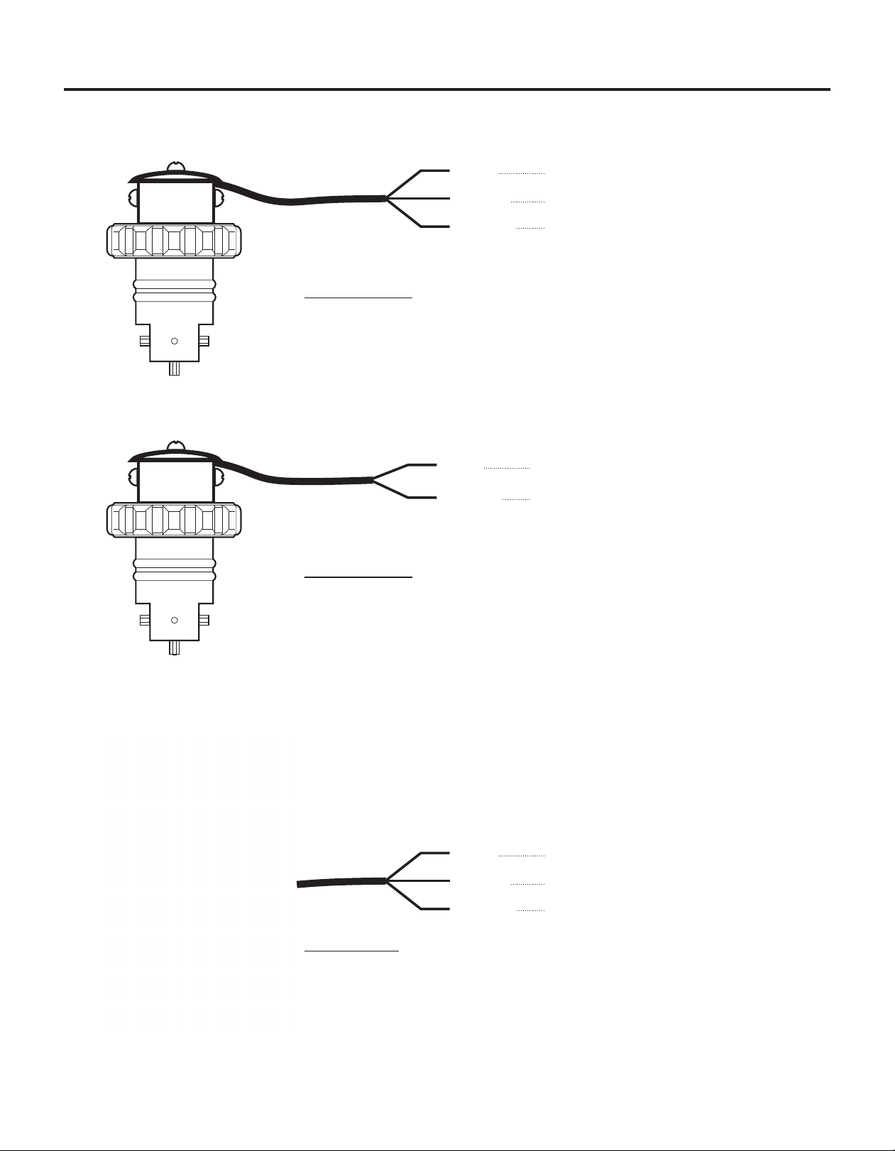
6.4 Model FHXX and FCXX Sensor wiring
Page 10
RED
BARE
BLACK
Input Supply Voltage (+ 6 to 24 Vdc)
Signal Output (square wave)
Ground (-)
Model FHXX
Note: Output type - current sinking type hall effect sensor (13.5mA max).
Pull-up resistor is recommended. 5k ohm across red & bare wires.
Approximately 10 to 350 Hz operating range.
RED
BLACK
Signal Output (Sine wave)
Ground (-)
Model FCXX
Note: Output type - AC sine wave. 100 mV peak to peak.
0.06 to 3.00 volts AC / 10uA to 500uA AC.
Approximately 10 to 350 Hz operating range.
RED
BARE
BLACK
Input Supply Voltage (+ 6 to 24 Vdc)
Signal Output (square wave)
Ground (-)
Model FVS
Find Quality Products Online at: sales@GlobalTestSupply.com
www.GlobalTestSupply.com

Page 11
F-2000
7.0 HOW TO OPERATE THE F-2000
7.1 Theory of Operation
The MODEL RT is the base unit of the F-2000 flow monitoring system. Fluid flowing through the pipe causes the
paddlewheel to spin. Pulses generated by the spinning paddlewheel are counted and multiplied by scaling factors. The
resulting flow rate amounts and total flow amounts are displayed on the LCD readout. Pressing the enter button located
on the front panel toggles the display between flow rate and total flow or allows entry into the programming mode.
Pressing the clear total button while the total flow value is displayed will return the total to zero (must be activated in the
programming mode - not the factory default setting). A small icon will light at the bottom of the LCD indicating the mode
being displayed.
The MODEL PC includes all of the features of the MODEL RT as well as a relay which can be used to switch external
electrical equipment when user programmed setpoints are reached. The relay must be assigned to respond to either the
rate value for rate alarm applications (rate mode), or to the total value for batching or proportional feed applications (batch
mode). Only one may made be used at any one time. When assigned to the batch mode, the display can be toggled to
show four different values, the rate of flow, total flow, current batch number or current batch total, by pressing the enter
button located on the front panel. A small icon will light at the bottom of the LCD display indicating the mode being
displayed. The model PC is described in a separate instruction manual.
The MODEL AO includes all of the features of the MODEL RT as well as a 4-20mA or 0-10VDC output signal which is
proportional to the flow rate value. This mode is always active although the output value can not be displayed on the LCD.
A small icon will light indicating the mode is active. The model AO is described in a separate instruction manual.
The MODEL AP includes the features of all three F-2000 models, the RT, PC, and AO.
7.2 How To Operate The MODEL RT
7.2.1 What Was The MODEL RT Designed To Do?
!
Display the rate of flow up to eight digits.
!
Display the total amount of flow up to eight digits.
!
Output an open collector signal (NPN) that is proportional to the flow rate.Operates by batteries or plug-in AC
transformer.
!
Greater than 1 year battery life.
!
Front panel user programmable.
!
Front panel programming can be disabled for security.
!
Front panel total reset can be disabled for security.
!
Programmable battery saving mode. (Screen blanks after 30seconds)
!
Programmable decimal point locations for both rate and total modes.
!
Display can be mounted on the sensor or panel mounted (1/4 DIN). See figure 6 and 8.
!
Display can be rotated on sensor. See figure 6.
!
Display can be mounted on a pipe or wall with optional mounting bracket kit. See figure 8 - 11.
!
Display can be panel mounted up to 250 ft. from sensor when used with AC coil sensor.
!
Display can be panel mounted up to 1 mile from sensor when used with Hall Effect sensor.
!
Optional circuitry, AO (analog output) and PC (process control) boards, can be field installed at a later time.
Find Quality Products Online at: sales@GlobalTestSupply.com
www.GlobalTestSupply.com
F-2000
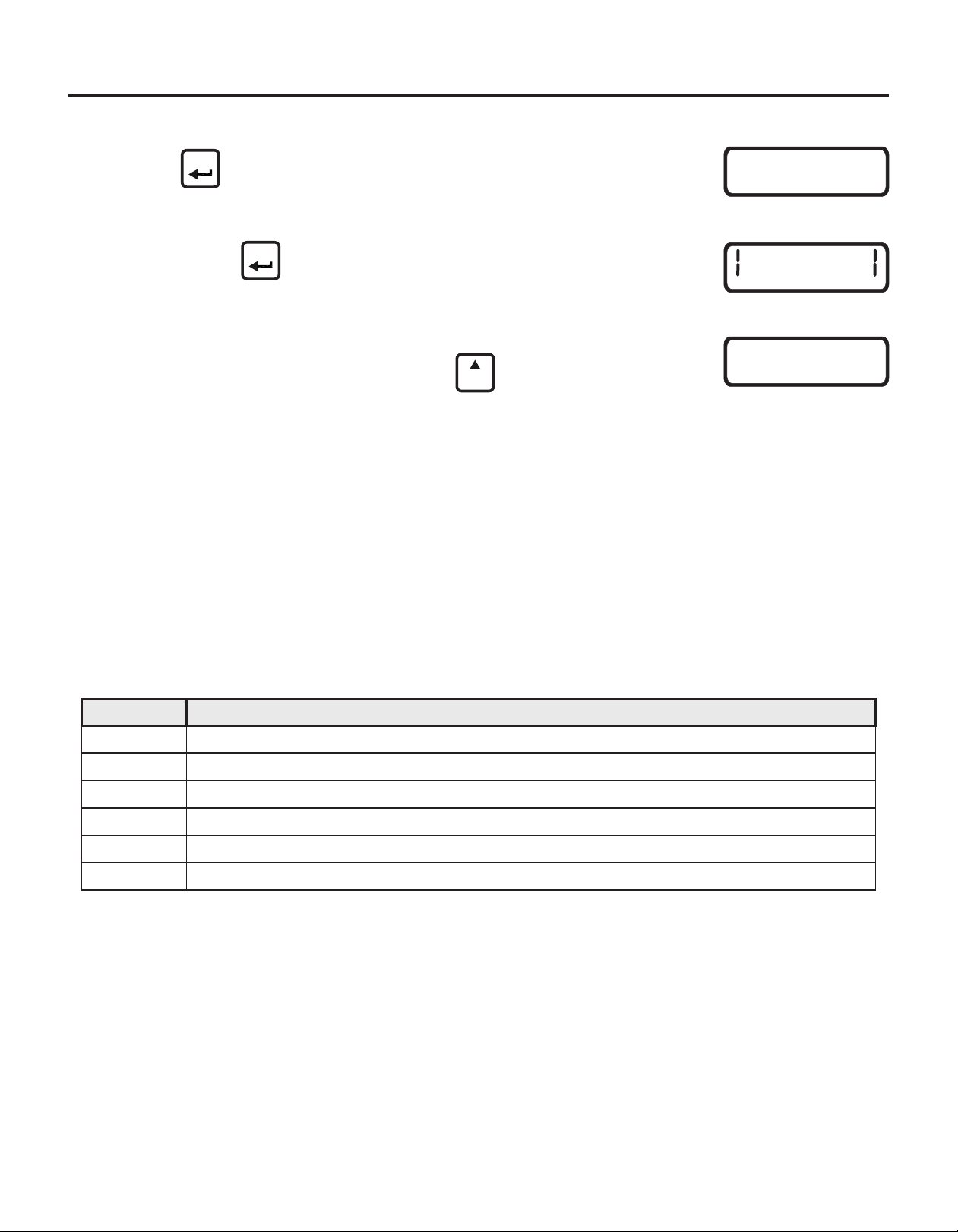
7.2.2 What Features Are Available On The MODEL RT?
Page 12
!
Press to toggle between RATE and TOTAL display modes. The icon will
light to indicate the active mode.
!
Press and hold for at least 1.25 seconds to enter the programming mode.
Allow twenty seconds to pass so the display will switch back to the readout
mode. See section 7.1.
!
While the TOTAL mode is displayed, press to reset the total amount to
zero. (Must be enabled in the program mode - see page 24, step 6.)
ENTER
ENTER
CLEAR
TOTAL
RATE TOTAL
00000
RATE
TOTAL
0
0
7.2.3 How Do I Determine My Calibration Numbers?
When ordered as a complete system, the F-2000 MODEL RT is factory programmed to the flow range you specified when
you placed your order. See section 4.0 for various flow ranges.
Note: The F-2000 model AO and PC functions will always require field programming. All F-2000 models will require field
programming when components are purchased separately. See section 7.2 and 7.3.
The following screens are used to input the calibration constants and to turn on or off the various features of the MODEL
RT. The MODEL RT has six different input screens. They are listed in the table below.
Screen No. Programming Functions
RATE 1
RATE 2
RATE 3
TOTAL 1
TOTAL 2
TOTAL 3
Before programming the unit, the following calibration constants must be determined. Remember, when
purchased as a complete system, the model RT is pre-programmed at the factory. No further programming is
necessary.
Toggle Battery Saving mode - on / off (factory default: off)
Toggle front panel Clear Total button - on (enabled) / off (disabled) -- (factory default: off)
Find Quality Products Online at: sales@GlobalTestSupply.com
www.GlobalTestSupply.com

Page 13
Step 1 Where would you like your displayed flow rate decimal point located?
F-2000
Desired Location = D (Decimal Rate Factor) Note: Four decimal places maximum.
XXXXX = 1
XXXX.X = 10
XXX.XX = 100
XX.XXX = 1000
X.XXXX = 10000 Enter your D here.
Step 2 What time factor would you like to use in your measurement?
Example: Per Minute = 60 seconds
Per Hour = 3600 seconds
Per Day = 86400 seconds
Fill in the amount of seconds you desire here.
Step 3 To determine your flow rate K-Factor, the following information is needed.
a. What size pipe you are going to install this meter on? inch pipe
b. What schedule pipe are you using? Sch 40 or Sch 80 or Inline
c. What is your flow range? Low Flow or Standard Flow (refer to pages 16 & 17)
r
r
d. Using the data you specified above, locate your K-Factor from the correct table. Pages 16 & 17.
e. What is your K-Factor?
f. If you are going to be using gallons as your unit of measure, you can go directly to Step 4.
g. To convert K-Factor to other units of measure, use the following formulas:
Ounces = K-factor ÷ 128
Liters = K-factor ÷ 3.785
Cubic Meters = K-factor ÷ 0.003785
Example: To convert 2” schedule 80 gallons K-factor to
liters, you will use the following formula:
Note: Locate your K-factor off the table on pages 16 & 17..
58.82 (K-factor)
3.785
= 15.54
Your new liters K-factor is 15.54
Write your new K-Factor number here.
Find Quality Products Online at: sales@GlobalTestSupply.com
www.GlobalTestSupply.com

F-2000
Page 14
Step 4 Calculate your Rate Scale Factor (S ) using the following formula.
D from Step 1, Seconds from Step 2, K-Factor from Step 3.
r
r
Example:
D x Seconds
S =
r
r
K-Factor
D = 10
r
Seconds = 3600
S =
10 x 3600
r
K-Factor = 63.52
S =
r
S =
r
Write your S (Rate Scale Factor) number here.
Step 5 Where would you like your displayed accumulated Total Decimal (D ) point located?
Desired Location = D (Total Decimal Factor) Note: Four decimal places maximum.
r
t
t
XXXXX = 1
XXXX.X = 10
XXX.XX = 100
XX.XXX = 1000
X.XXXX = 10000 Enter your D here.
t
63.52
36000
63.52
566.751
Step 6 Determine your Total K-factor.
Your Total K-factor and Flow Rate K-factor are the same if the same units (i.e., Gallons, liters, etc.) Are
displayed for both. However, you can use a different unit of measure for your total display. Follow the
instructions in step 3-g to convert to a different Total K-factor unit.
Write your Total K-factor here.
Step 7 Calculate your Total Scale Factor (S ) using the following formula.
D
S =
t
t
K
t
Example:
D
S =
t
K
S =
t
S =
Note: The Total Scale Factor may be
carried out to four decimal places.
t
58.82
t
1
00.0170
Write your Total Scale Factor (S ) here.
Find Quality Products Online at: sales@GlobalTestSupply.com
www.GlobalTestSupply.com
t

Page 15
F-2000
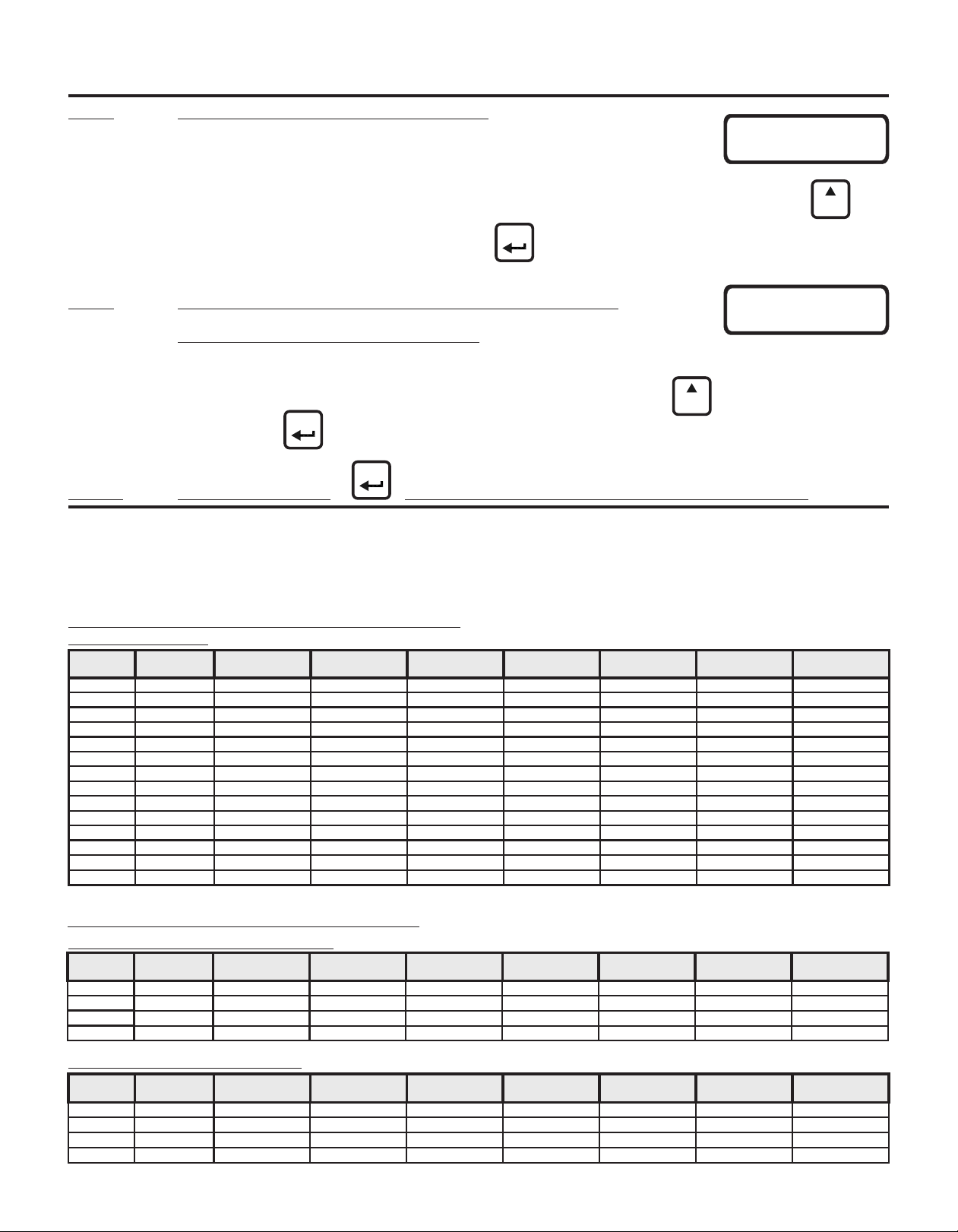
7.2.4 How Do I Program The MODEL RT?
Note: While in the programming mode, if no buttons are pressed within twenty seconds, the programming mode is
automatically exited without saving the input of the last screen. See page 18 for programming menu flow chart.
Step 1 Entering the Rate Scale Factor.
!
Press and hold down for at least 1.25 seconds.
!
Enter the Rate Scale Factor (Sr from Step 4, page 14).
!
Press to select the digit to be modified or the decimal point. Note: The selected digit will blink to notify you
it is selected.
!
Press to modify the selected digit or the decimal point. Repeat the process until all digits have been
modified.
!
When finished, press . This will move you to the RATE 2 screen.
Step 2 The Rate Decimal Point Location screen.
!
Press once to see the decimal point appear. Press repeatedly until the
decimal point is located in the desired location. Then press to move you to RATE 3.
!
This value should match Page 13, Step 1, desired decimal location. Ex. 0000.0
CLEAR
SETPOINT
CLEAR
TOTAL
CLEAR
TOTAL
ENTER
ENTER
ENTER
CLEAR
TOTAL
000000
RATE
2
RATE
00000
Step 3 The Battery Save Mode On / Off screen. Factory default = OFF
!
Press to toggle the ON and OFF settings. Press once you’ve selected
your setting.
Step 4 The Total Scale Factor screen is selected.
!
Enter the Total Scale Factor (S from Step 7, page 14).
!
Press to select the digit to be modified or the decimal point. Note: The selected digit will blink to notify you
it is selected.
!
Press to modify the selected digit or the decimal point. Repeat until all digits have been Entered.
!
When finished, press . This will move you to the TOTAL 2 screen.
CLEAR
TOTAL
CLEAR
SETPOINT
CLEAR
TOTAL
t
ENTER
ENTER
3
RATE
000000
TOTAL
OFF
Find Quality Products Online at: sales@GlobalTestSupply.com
www.GlobalTestSupply.com
F-2000
Step 5 The Total Decimal Point screen is selected.
!
The Total 2 screen is where you enter your Decimal Point Factor for your totalizer.
Use the information you calculated on D , on Page 14, Step 5. Move the decimal point by pressing the until
the decimal point is in the desired location. Then press . Ex. 00000
t
ENTER
Page 16
000000
2
TOTAL
CLEAR
TOTAL
Step 6 The Front Panel Clear Total Button Enable / Disable screen is
selected. Factory default = OFF (disabled)
!
The Total 3 screen gives you the option to turn on or off the clear total button function. It was designed to prevent
the user from making the mistake of clearing the totalizer screen. By pressing the you can scroll through the
ENTER
CLEAR
TOTAL
3
TOTAL
Off
on and off mode. Press once you have made your selection.
ENTER
Step 7 Press and hold down for at least 1.25 seconds to exit the programming mode.
7.2.6 Calibration Constants
Note: The values in the following tables are based on laboratory testing of nominal pipe dimensions. The F-2000 sensor is factory calibrated to ±1%
of full scale linearity. Your actual accuracy will vary based on your pipe I.D. And other installation factors.
METRIC PIPE PN10 & PN16 (Meets DIN 8062)
Saddle Mount Models (Pipe Insertion connection)
Standard Flow Range - LPM (liters per minute)
Pipe Size
(MM)
50
50
63
63
90
90
110
110
160
160
200
PN
Rating
10
16
10
16
10
16
10
16
10
16
10
16200 170.2 1150 - 11500 1.008 59.5501 00000 00.9925 00000
10250 226.2 1700 - 17000 0.565 106.232 00000 01.7705 00000
10315 285.0 2700 - 27000 0.353 170.003 00000 02.8334 00000
Pipe I.D. (MM)
45.2
42.6
57.0
53.6
81.4
76.6
99.4
93.6
144.6
136.2
180.8
Flow Range
(LPM)
70.0 - 700.0
70.0 - 700.0
110 - 1100
110 - 1100
230 - 2300
230 - 2300
350 - 3500
350 - 3500
720 - 7200
720 - 7200
1150 - 11500
K-Factor
(Pulse/L)
16.561
20.719
10.522
11.830
5.294
5.944
2.942
3.107
1.386
1.574
0.927
RATE 1 RATE 2
Rate Scale
Factor (Sr)
36.2297
28.9588
05.7023
05.0720
11.3335
10.0944
20.3969
19.3133
43.2782
38.1081
64.7077
Rate Display
Decimal Point
0000.0
0000.0
00000
00000
00000
00000
00000
00000
00000
00000
00000
TOTAL 1 TOTAL 2
Total Scale
Factor (St)
00.0604
00.0483
00.0950
00.0845
00.1889
00.1682
00.3399
00.3219
00.7213
00.6351
01.0785
Total Display
00000
00000
00000
00000
00000
00000
00000
00000
00000
00000
00000
I.P.S. PIPE (Meets ASTM-D-1785)
Molded Inline Bodies (Male NPT connection)
3/8” - 1” pipe sizes - Standard Range #1 - GPM (gallons per minute)
Pipe Size
(in.)
3/8
1 /2
3/4
1.0
Pipe Sch.
Inline
Inline
Inline
Inline
Body I.D. (In.)
0.375
0.500
0.660
0.840
Flow Range
(GAL/Min)
.800 - 8.000
2.00 - 20.00
3.00 - 30.00
5.00 - 50.00
K-Factor
(Pulse/GAL)
1456.31
1034.48
612.25
338.60
3/8” - 1” pipe sizes - Low Range #2 - GPM (gallons per minute)
Pipe Size
(in.)
3/8
1/2
3/4
1.0
Pipe Sch.
Inline
Inline
Inline
Inline
Body I.D. (In.)
0.218
0.250
0.375
0.500
Find Quality Products Online at: sales@GlobalTestSupply.com
Flow Range
(GAL/Min)
.400 - 4.000
.500 - 5.000
.800 - 8.000
2.00 - 20.00
K-Factor
(Pulse/GAL)
2926.83
2419.35
1518.99
1034.48
www.GlobalTestSupply.com
RATE 1 RATE 2 TOTAL 1 TOTAL 2
Rate Scale
Factor (Sr)
41.2000
05.8000
09.8000
17.7200
RATE 1
Rate Scale
Factor (Sr)
20.5000
24.8000
39.5000
05.8000
Rate Display
Decimal Point
00.000
000.00
000.00
000.00
Total Scale
Factor (St)
00.0069
00.0097
00.0163
00.0295
Total Display
Decimal Point
0000.0
0000.0
0000.0
0000.0
RATE 2 TOTAL 1 TOTAL 2
Rate Display
Decimal Point
00.000
00.000
00.000
000.00
Total Scale
Factor (St)
00.0034
00.0041
00.0066
00.0097
Total Display
Decimal Point
0000.0
0000.0
0000.0
0000.0

Page 17
Molded Inline Bodies (Male NPT connection) - continued
1-1/2” - 2” pipe sizes - GPM (gallons per minute)
Pipe Size
(in.)
1-1/2
1-1/2
1-1/2
2
2
2
2 4 20.0 - 200.0 67.416 8.9000 0000.0 00.1483 0000.0
Pipe Sch.
Inline
Inline
Inline
Inline
Inline
Inline
Inline
Flow Range #
1
2
3
1
2
3
Flow Range
(GAL/Min)
4.00 - 40.00
6.00 - 60.00
10.0 - 100.0
4.00 - 40.00
6.00 - 60.00
10.0 - 100.0
K-Factor
(Pulse/GAL)
466.20
192.93
156.94
468.75
196.40
162.16
Machined Inline Bodies (Female NPT connection)
Standard Flow Range #1 - GPM (gallons per minute)
Pipe Size
(in.)
3/8
1/2
3/4
1.0
1-1/2
2.0
Pipe Sch.
Inline
Inline
Inline
Inline
Inline
Inline
Body I.D. (In.)
0.375
0.500
0.750
1.000
1.500
1.900
Low Flow Range #2 - GPM (gallons per minute)
Pipe Size
(in.)
3/8
1/2
3/4
1.0
1-1/2
2.0
Pipe Sch.
Inline
Inline
Inline
Inline
Inline
Inline
Body I.D. (In.)
0.218
0.250
0.375
0.500
1.250
1.500
Low Flow Ranges #3, 4, 5, 6 - GPM (gallons per minute)
Pipe Size
(in.)
1-1/2
1-1/2
1-1/2
2.0
2.0
2.0
2.0
Pipe Sch.
Inline
Inline
Inline
Inline
Inline
Inline
Inline
Flow Range #
3
4
5
3
4
5
6 2.00 - 20.00 950.87 6.3100 000.00 00.0105 0000.0
Flow Range
(GAL/Min)
.800 - 8.000
2.00 - 20.00
4.00 - 40.00
6.00 - 60.00
15.0 - 150.0
30.0 - 300.0
Flow Range
(GAL/Min)
.400 - 4.000
.500 - 5.000
.800 - 8.000
2.00 - 20.00
10.0 - 100.0
15.0 - 150.0
Flow Range
(GAL/Min)
6.00 - 60.00
2.00 - 20.00
1.00 - 10.00
10.0 - 100.0
6.00 - 60.00
4.00 - 40.00
K-Factor
(Pulse/GAL)
1469.87
985.22
471.70
204.08
86.120
48.884
K-Factor
(Pulse/GAL)
3468.21
2631.58
1469.87
985.22
155.00
89.020
K-Factor
(Pulse/GAL)
217.39
1076.60
1283.88
162.47
224.67
493.83
Saddle Models (Pipe insertion connection)
Standard Flow Range - GPM (gallons per minute)
Pipe Size
(in.)
1.5
1.5
2.0
2.0
2.5
2.5
3.0
3.0
4.0
4.0
6.0
6.0
8.0
8.0
10.0
10.0
12.0
12.0
Pipe Sch. Pipe I.D. (In.)
40
80
40
80
40
80
40
80
40
80
40
80
40
80
40
80
40
80
1.610
1.500
2.067
1.939
2.469
2.323
3.068
2.900
4.026
3.826
6.065
5.761
7.981
7.625
10.020
9.564
11.938
11.376
Flow Range
(GAL/Min)
15.0 - 150.0
15.0 - 150.0
30.0 - 300.0
30.0 - 300.0
40.0 - 400.0
40.0 - 400.0
60.0 - 600.0
60.0 - 600.0
100 - 1000
100 - 1000
250 - 2500
250 - 2500
400 - 4000
400 - 4000
600 - 6000
600 - 6000
800 - 8000
800 - 8000
K-Factor
(Pulse/GAL)
86.580
102.04
50.850
58.820
34.8635
39.200
21.820
24.000
11.8577
12.7659
5.3507
5.5738
2.985
2.940
1.594
1.845
1.116
1.296
RATE 1 RATE 2 TOTAL 1 TOTAL 2
Rate Scale
Factor (Sr)
12.8700
31.0994
3.8231
12.8000
30.5499
3.7000
Rate Display
Decimal Point
000.00
000.00
0000.0
000.00
000.00
0000.0
Total Scale
Factor (St)
00.0215
00.0518
00.0637
00.0213
00.0509
00.0617
RATE 1 RATE 2 TOTAL 1 TOTAL 2
Rate Scale
Factor (Sr)
40.8200
06.0900
12.7200
29.4000
6.9670
12.2740
Rate Display
Decimal Point
00.000
000.00
000.00
000.00
0000.0
0000.0
Total Scale
Factor (St)
00.0068
00.0102
00.0212
00.0490
00.0116
00.0205
RATE 1 RATE 2 TOTAL 1 TOTAL 2
Rate Scale
Factor (Sr)
17.3000
22.8000
40.8200
06.0900
3.8710
6.7401
RATE 1 RATE 2
Rate Scale
Factor (Sr)
27.6002
5.5731
4.6733
3.6930
26.7058
12.1500
Rate Display
Decimal Point
00.000
00.000
00.000
000.00
0000.0
0000.0
Rate Display
Decimal Point
000.00
000.00
000.00
0000.0
000.00
000.00
Total Scale
Factor (St)
00.0029
00.0038
00.0068
00.0102
00.0065
00.0112
TOTAL 1 TOTAL 2
Total Scale
Factor (St)
00.0460
00.0093
00.0078
00.0062
00.0445
00.0203
RATE 1 RATE 2 TOTAL 1 TOTAL 2
Rate Scale
Factor (Sr)
06.9300
05.8800
11.7994
10.2006
17.2010
15.3061
27.4977
25.0000
05.0600
04.7000
11.2135
10.7647
20.1000
20.4082
37.6412
32.5203
53.7634
46.2963
Rate Display
Decimal Point
0000.0
0000.0
0000.0
0000.0
0000.0
0000.0
0000.0
0000.0
00000
00000
00000
00000
00000
00000
00000
00000
00000
00000
Total Scale
Factor (St)
00.0116
00.0098
00.0197
00.0170
00.0287
00.0255
00.0458
00.0417
00.0843
00.0783
00.1869
00.1794
00.3350
00.3401
00.6274
00.5420
00.8961
00.7716
F-2000
Total Display
Decimal Point
0000.0
0000.0
0000.0
0000.0
0000.0
0000.0
Total Display
Decimal Point
0000.0
0000.0
0000.0
0000.0
00000
00000
Total Display
Decimal Point
0000.0
0000.0
0000.0
0000.0
00000
00000
Total Display
Decimal Point
0000.0
0000.0
0000.0
00000
0000.0
0000.0
Total Display
Decimal Point
00000
00000
00000
00000
00000
00000
00000
00000
00000
00000
00000
00000
00000
00000
00000
00000
00000
00000
Find Quality Products Online at: sales@GlobalTestSupply.com
www.GlobalTestSupply.com

F-2000
7.3 Programming Menu Flow Chart
Page 18
ENTER
ENTER
ENTER
ENTER
ENTER
ENTER
ENTER
SCREEN
000000
RATE
00000
2
RATE
3
RATE
O00000
TOTAL
00000
2
TOTAL
3
TOTAL
MODEL PC UNITS ONLY
sETPOINT
CLEAR
TOTAL
RATE sETPOINT
OFF
OFF
OFF
DESCRIPTION
MODIFYING
RATE 1 - Rate Scale Factor
RATE 2 - Rate Decimal Factor
RATE 3 - Battery Save Mode On / Off
TOTAL 1 - Total Scale Factor
TOTAL 2 - Total Decimal Factor
TOTAL 3 - Clear Total Enable On / Off
SETPOINT MODE ASSIGN - on rate / on batch / off
Setpoint ON - Assigned to RATE
CLEAR
SETPOINT
CLEAR
TOTAL
CLEAR
TOTAL
CLEAR
SETPOINT
CLEAR
TOTAL
CLEAR
TOTAL
Or
Or
CLEAR
TOTAL
CLEAR
TOTAL
ENTER
ENTER
ENTER
ENTER
ENTER
CLEAR
TOTAL
BATCH SETPOINT
ENTER
ENTER
ENTER
MODEL AO UNITS ONLY
00000
RATE SETPOINT
00000
2
RATE SETPOINT
00000
3
RATE SETPOINT
00000
4
RATE SETPOINT
5
RATE SETPOINT
BATCH SETPOINT
2 OFF
BATCH SETPOINT
3
BATCH SETPOINT
000
00000
00000
Setpoint Rate 1 - High Alarm Trigger
Setpoint Rate 2 - High Alarm Release
Setpoint Rate 3 - Low Alarm Trigger
Setpoint Rate 4 - Low Alarm Release
Setpoint Rate 5 - Alarm Delay Timer
Setpoint ON - Assigned to BATCH
Setpoint Batch 1 - Batch Amount
Setpoint Batch 2 - Auto Reset On / Off
Setpoint Batch 3 - External Equip. Timer
CLEAR
SETPOINT
CLEAR
SETPOINT
CLEAR
SETPOINT
CLEAR
SETPOINT
CLEAR
SETPOINT
CLEAR
SETPOINT
CLEAR
SETPOINT
CLEAR
SETPOINT
Or
Or
Or
Or
Or
Or
Or
Or
CLEAR
TOTAL
CLEAR
TOTAL
CLEAR
TOTAL
CLEAR
TOTAL
CLEAR
TOTAL
CLEAR
TOTAL
CLEAR
TOTAL
CLEAR
TOTAL
ENTER
ENTER
Find Quality Products Online at: sales@GlobalTestSupply.com
00000
MA
00000
2
MA
www.GlobalTestSupply.com
MA-1 - Low Analog Out Value
MA-2 - High Analog Out Value
CLEAR
SETPOINT
CLEAR
SETPOINT
Or
Or
CLEAR
TOTAL
CLEAR
TOTAL
Page 19
8.0 MAINTENANCE
The F-2000 requires very little maintenance, however, some conditions will cause increased wear or
possible damage to the unit.
!
Periodically remove the sensor assembly from the pipe fitting and inspect the meter for signs of wear
and obstructions. Clean the paddle of any foreign objects. Replace the paddle and axle if worn.
!
Although the meter is capable of operating at the high end of the flow range, continuous use at very
high flow rates (upper 25% of the calibrated flow range), is not recommended. The paddle and axle life
is related to the rate of flow and the fluid being measured. Corrosive fluids moving at high flow rates
will cause increased wear requiring frequent inspection and maintenance. Ceramic, titanium or nickel
axles are available for extreme corrosive environments.
!
Although the F-1000 is designed to withstand outdoor conditions, a cool, dry location where the unit can
be easily serviced is recommended. The life of the LCD display will be severely reduced when
installed in direct sunlight. Do not install the meter so that the LCD is in direct sunlight.
!
O-rings should be inspected periodically. Immediately replace the o-rings at any sign of wear, swelling,
cracking or discoloration.
!
Battery operated models. Replace the four AA batteries every 12 months. The program memory will
not erase when replacing the batteries. The unit will function normally for approximately 2 minutes
while replacing the batteries. To replace the batteries, open the front panel of the enclosure by
removing the four Phillips screws. After replacing the batteries, be sure the foam insert is in place
before closing the front panel.
!
Test the electronics by removing the sensor assembly from the pipe fitting and spinning the paddle by
hand. If a reading does not appear in the display window, replace the batteries. If a reading still does
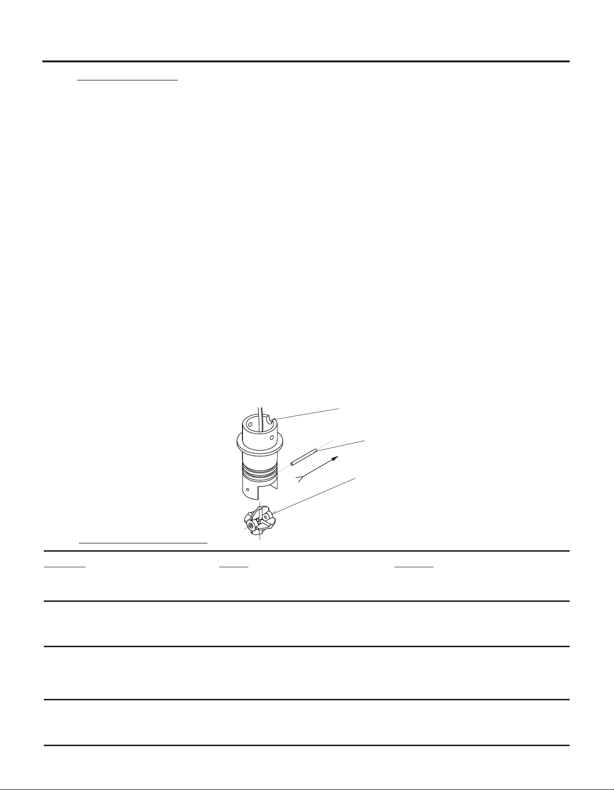
F-2000
Step 1: Locate notch on the sensor
PADDLE REMOVAL
Fig. 12
Arrow
Direction
Step 2: Push shaft out in the direction shown.
Step 3: Replace the paddle, then press shaft
back into place in the opposite
8.1 TROUBLESHOOTING
Situation Cause Solution
Leaking Improper installation Pipe Fitting Manual pages 6 thru 10
Worn or damaged o-rings Pipe Fitting Manual pages 6 thru 10
Flow rate reading is inaccurate Improper installation Pipe Fitting Manual page 6
Improper velocity profile Pipe Fitting Manual page 4
Flow rate is out of range Model RT Manual page 4
No display Dead batteries Model RT Manual page 19
Blocked paddle Pipe Fitting Manual page 7
Damaged electronics Model RT Manual page 19
Battery save mode is ON Model RT Manual page 18
Display shows zero flow Improper alignment / installation Pipe Fitting Manual page 7
Worn paddle and / or axle Model RT Manual page 19
Damaged electronics Model RT Manual page 19
Find Quality Products Online at: sales@GlobalTestSupply.com
www.GlobalTestSupply.com

Item Part Number Description Quantity
F-2000
F-2000 Parts List
Item Part Number Description Quantity
1 70000-783 Paddle assembly Kynar 1
2 90003-021 O-ring 022 Viton E60 2
3 90007-589 Axle PVDF 1
4 71000-238 Sensor body AC coil 1’ cable 1
71000-289 Sensor body AC coil 25’ cable 1
70000-290 Sensor body Hall effect 25’ cable 1
5 90011-080 Screw #6-32 x .37 PH pan B 18/8 5
6 91001-280 Union nut 1
7 76000-628 Retainer sensor cap 1
8 90006-550 Cap sensor body SS 1
9 90012-208 Switch overlay F-2000 1
10 71000-356 Cover F-2000 w/ Switch overlay 1
11 90006-592 Gasket F-2000 housing neoprene 1
12 90010-227 Circuit board F-2000 RT 1
13 71000-311 Kit Circuitry model F-2000 AO (AO Board 90010-229) 1
14 71000-316 Kit Circuitry model F-2000 PC(PC Board 90010-228) 1
15 90011-155 Screw #6-32 x .31 PH pan SS 4
16 76001-149 Enclosure F-2000 sensor mount 1
76001-150 Enclosure F-2000 panel mount 1
17 90006-593 Gasket F-2000 1/4 DIN panel mount 1
18 90008-331 Cap plug P-48 1/2 NPT red F-2000 1
19 71000-294 Kit F-2000 1/4 DIN panel mount 1
20 70000-500 Connector liquid-tight 1/2 in. 2
21 70000-589 Connector liquid-tight 3/4 in. 1
22 90008-332 Plug 1/2 in. 2
23 90008-340 Cap plug VTP-25 red 1
24 90011-038 Stud screw #10-32 1.62 long 2
25 90011-092 Star washer #10-32 2
26 90011-026 Hex nut #10-32 2
27 90008-333 Plug 7/8 in. 1
28 90013-222 Foam pad 1/4 in. thick 1
29 90008-254 Battery clip 1
30 90010-233 Battery holder F-2000 4x AA 1
31 90008-330 Battery alkaline AA 4
32 90008-336 Power supply 115VAC/15VDC 1
90008-337 Power supply 220VAC/15VDC Europe 1
71000-310 Power supply 230VAC/15VDC 1
Page 20
Find Quality Products Online at: sales@GlobalTestSupply.com
www.GlobalTestSupply.com
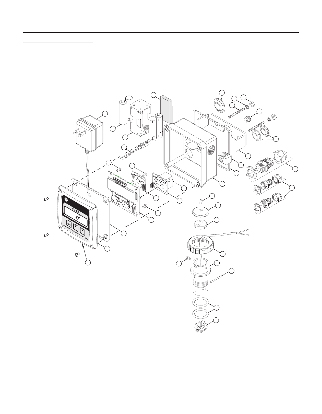
Page 21
F-2000 Exploded View
F-2000
BLUE-WHITE
®
INDUSTRIES
F-2
0
00
ENTER
CLEAR
Flow Monitoring System
SETPOINT
CLEAR
T
OT
28
27
26
25
24
32
SIZE AA BATTERY
23
31
30
SIZE AA BATTERY
22
29
19
5
15
18
21
17
8888.8888
15
13
14
16
20
5
8
15
12
AL
11
7
10
6
9
5
4
3
2
1
Find Quality Products Online at: sales@GlobalTestSupply.com
www.GlobalTestSupply.com

Warranty
!
Blue-White flowmeters are warranted to be free from defects in material and workmanship for 12 months from date of
factory shipment. Warranty coverage is limited to repair or replacement of the defective flowmeter only.
!
This warranty does not cover damage to the flowmeter that results from misuse or alterations, nor damage that occurs
as a result of: meter misalignment, improper installation, over tightening, use of non-recommended chemicals, use of
non-recommended pipe dopes or adhesives, excessive heat or pressure or allowing the meter to support the weight of
related piping.
!
Flowmeters are repaired at the factory only. Call or write the factory to receive a RA (return authorization) number.
Carefully pack the flowmeter to be returned, including a brief description of the problem, chemical used, and a description of the application. Note: Write the RA number on the outside of the shipping carton.
!
Prepay all shipping costs. The factory does not accept C.O.D. Shipments. Damage that occurs during shipping is the
responsibility of the sender.
Users of electrical and electronic equipment (EEE) with the WEEE marking per Annex IV of
the WEEE Directive must not dispose of end of life EEE as unsorted municipal waste, but
use the collection framework available to them for the return, recycle, recovery of WEEE
and minimize any potential effects of EEE on the environment and human health due to the
presence of hazardous substances. The WEEE marking applies only to countries within the
European Union (EU) and Norway. Appliances are labeled in accordance with European
Directive 2002/96/EC.
P.N. 80000-355 Rev 6/25/2014
Find Quality Products Online at: sales@GlobalTestSupply.com
Contact your local waste recovery agency for a Designated Collection Facility in your area.
www.GlobalTestSupply.com
 Loading...