

Blue Wave Pools NB2540 Installation Manual

UNIV E RSAL INS TRUCTIONS
BRACE D OVAL P O OL S
PLE AS E READ THE SE INSTRUCTI O NS CAREFULL Y AND THOROUGHL Y BEFORE
STARTING GROUND PREPARATION A ND POOL ASSEMBLY.
DOING SO WILL PREVENT PROBLEMS.
Page.
Oval Pool: General informaition -----------------------------------
1) Selection pool site -----------------------------------------------
2) Ground preparation ----------------------------------------------
3) Assembling side vertical,Hor izontal support and brace-
4) Drawing pool shape ----------------------------------------------
5) Connecting tension straps --------------------------------------
6) Positioning assembled oval parts -----------------------------
7) Assembling bottom rail ------------------------------------------
8) Installing wall -------------------------------------------------------
9) Build an earth mound(Cove) -----------------------------------
10) Through the wall skimmer --------------------------------------
11) Liner installation ---------------------------------------------------
1
1
2
3
5
7
7
8
8
9
9
9
Please refer to "Assemble TopSeat , Vert ical and Cover" of an attached sheet.
12) Filling the pool -----------------------------------------------------
13) Helpful information -----------------------------------------------
14) SAFETY RULES -------------------------------------------------BRACED O VAL Parts List (#A OVAL CARTON) --------------
10
10
10
11
GENERA L INFORMATION
Befor e attempting to set up the pool, read the ent ire
instructions. There are certain areas in the instruct ions that are
extr emely i mportant to fol low exactly as written and/ or pictured.
Any deviation fr om t hese instruct ions voi ds warranty of the pool
and coul d cause bodily har m or damage t o your property.
Open the cartons and remove all par ts except st eel wall and liner .
Before pool assembly, you must identify, count and c heck all part s for
assembly by parts list. Familiarize yourself wit h all of the part s. Refer
to the parts list.
1) SELECTION OF POOL SITE
Before starti ng the i nstallat ion, the fol lowing points are
important;
a) The si te must be large enough to accom modate the pool with
plenty of area around it f or pool accessaries, chairs, tabl es etc.
b) Determine where your filtration andskimmer will be located.
It must be connected to a grounded 110 volt electrical outlet,
with a G.F.I. (Ground Fault In terrupter)
c) The pool must be in reach of your water supply. A lthough t he
water should not be drained, but kept clean t hr o ugh fi ltration and
chem icals, there should be drainage facilities near in case of need.
CAUTION:
Do not start the installation of your pool unless you have
an entire day t o finish the work.
Do not try to set up your pool on a windy day.
The wall will be di fficult or even impossible to handle.
d) Perimeter area of ground must be absolutely l evel and firm. All
grass and sod under entire pool area must be dug out t o avoid
unpleasant odors from decomposition under the pool due to lack of
air. Remove sharp objects, stones, twigs, pebbles, roots, etc.
They may damage the liner. If the gr ound has been t r eated with
chemicals or weed killer all ow two weeks before setting up the pool.
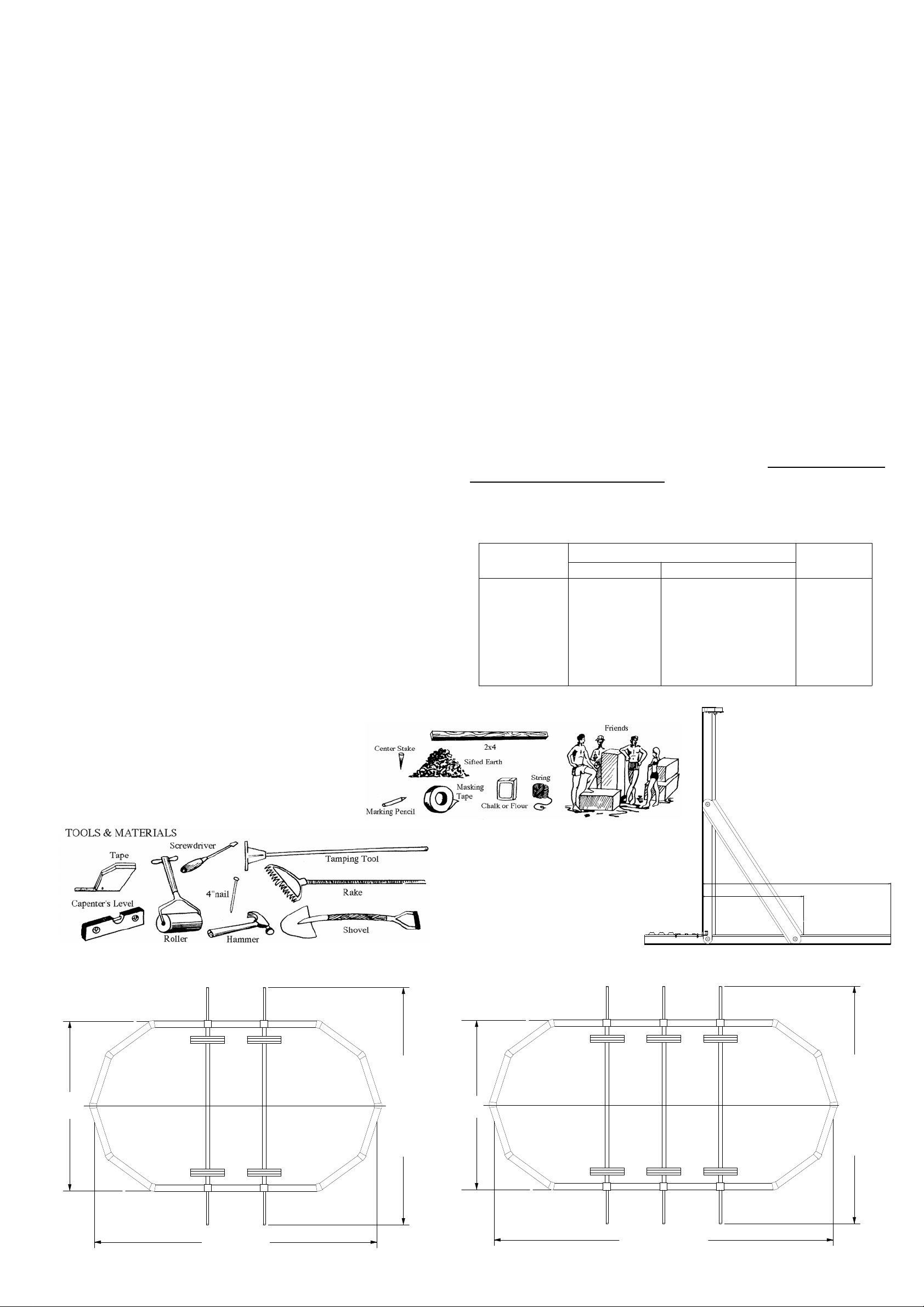
An average pool needs 2 or 3 people f or
installation.
The following tool s and materials are needed.
Do not set up t he pool on concrete, asphalt, tar paper, peatmoss,
sand, gravel, or where nut grass has been planted.
Poorly prepared ground could allow certain weeds or grass to grow
through the liner. Liner is not warranted against this. If ground is
unev en in perimeter area, dig out the hi gh spots. Do not build up the
Screwdriver
Tamping Tool
Pegs and
Stakes
Carpenter's
Level
Measuring Tape
Patio Block
Earth Roller
String
Hammer &
Nails
Sand
2"x4" Boar d
Shovel
Marking
Pencil
Masking
Tape
Rake
Chalk or
Flour
low side by padding it with earth. The weight and movem ent of the
water will pack down the fill causi ng the pool to sink. Inside
perimeter of pool (the area inside of t he frame and wall ) c an be
leveled with 1" or 2" of sand raked and rolled sm ooth.
Plastic Ta pe
FAILURE TO OBSERVE ANY O F THE ABOVE INSTRUCTIONS
WILL VOID W ARRANTY.
SIFTED EARTH OR SAND NEEDED
PER EACH SIZE POOL AS FOLLOWS:
16' x 12' 26 cubic feet 0.79cubic M
20' x 12' 34 cubic feet 0.96cubic M
24' x 12' 42 cubic feet 1.19cubic M
25' x 15' 54 cubic feet 1.53cubic M
30' x 15' 66 cubic feet 1.87cubic M
33' x 18' 87 cubic feet 2.46cubic M
41' x 21' 127 cubic feet 3. 59c ubicM
POOL SIZ E Wall Length Top Sheet
mm ft in
.
Q'ty
1612 13,855 45 5 4/8 12
2012 16,364 53 8 2/8 14
2412 18,873 61 11 16
2515 20,625 67 8 14
3015 23,756 77 11 2/8 16
3318 26,586 87 2 6/8 18
4121 32,549 106 9 4/8 22
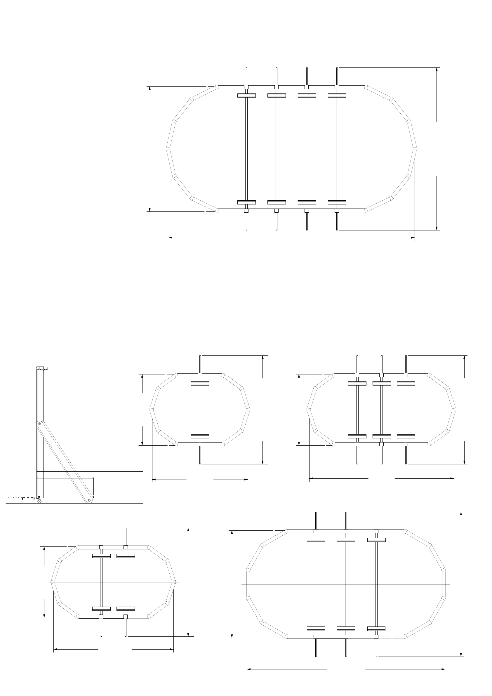
48" Oval F r ame
(4572mm)
(960mm)
3'
1-3/4"
(542mm)
1'
9-3/8"
15'
25x15
6- 3/4" (48" W al l )
10-3/4" (52" Wall)
(6269mm)
(6370mm)
20'
20'
(4572mm)
15'
30x15
10-3/4" (52" Wall)
(6269mm)
(6370mm)
20'
20' 6- 3/4" (48" W al l )
(7656mm)
25'
1-3/8"
1
(9198mm)
30'
2-1/8"
2) GROUND PREPARATION
The preparation of the
ground is the most
important step in the
installation of the pool.
a) Mark off your pool area
by driving stakes. Hav e a
helper hold a tape measure
or a string and mark off the
pool perimeter using flour
or chalk. Remove sod inside
thepoolareatoadistance
of 1 feet beyond di mensions
shown in the plot layout
around entire perimeter
of pool.
b) Remove all grass from
within the entire pool area.
It is not enough to just cut
the grass. The sod m ust
be removed.
21'
(6401mm)
(12570mm)
41'
2-7/8"
41x21
(8161mm)
1-1/4" (52" Wall)
26' 9-1/4" (48" Wall )
(8262mm)
27'
c) Two or three inches of sand is t he best for your liner . Using sand eliminates the necessit y to level inside of fr ame area except where
except ionally high or low areas exist.
These areas should either be dug or filled in. This does not m ean the perimeter or frame area. That area must be firm and level by digging
only.
d) Do not fill low spots in the area where pool wall will rest. as setting m a y cause your pool t o beco me out of le vel.
Making sure pool bottom is flat.This is a must.
e) If your site is not on firm soil, use 2" patio blocks for the base of t he wall Care should be taken to center a patio
block under each bottom plate. The top of the patio blocks should be flush with the prepared ground surface.
10-1/8"
(3611mm)
11'
24x12
52" Oval F r ame
10-1/8"
(3611mm)
11'
16x12
(5355mm)
6-7/8" (48" Wall)
10-7/8" (52" Wall)
17'
17'
(5456mm)
(5355mm)
6-7/8" (48" Wall)
10-7/8" (52" Wall)
17'
17'
(5456mm)
10-1/8"
11'
(3611mm)
(575mm)
1'
10-5/8"
(1011mm)
3'
3-3/4"
20x12
(4847mm)
15'
6-7/8" (48" Wall)
17'
(5355mm)
(5456mm)
10-7/8"
10-7/8" (52" Wall)
17'
18'
(5487mm)
(7319mm)
24'
1/8"
33x18
(7220mm)
1/4" (52" Wall)
24'
23' 8-1/4" (48" Wall)
(7321mm)
(6083mm)
19'
11-4/8"
2
(10112mm)
33'
2-1/8"
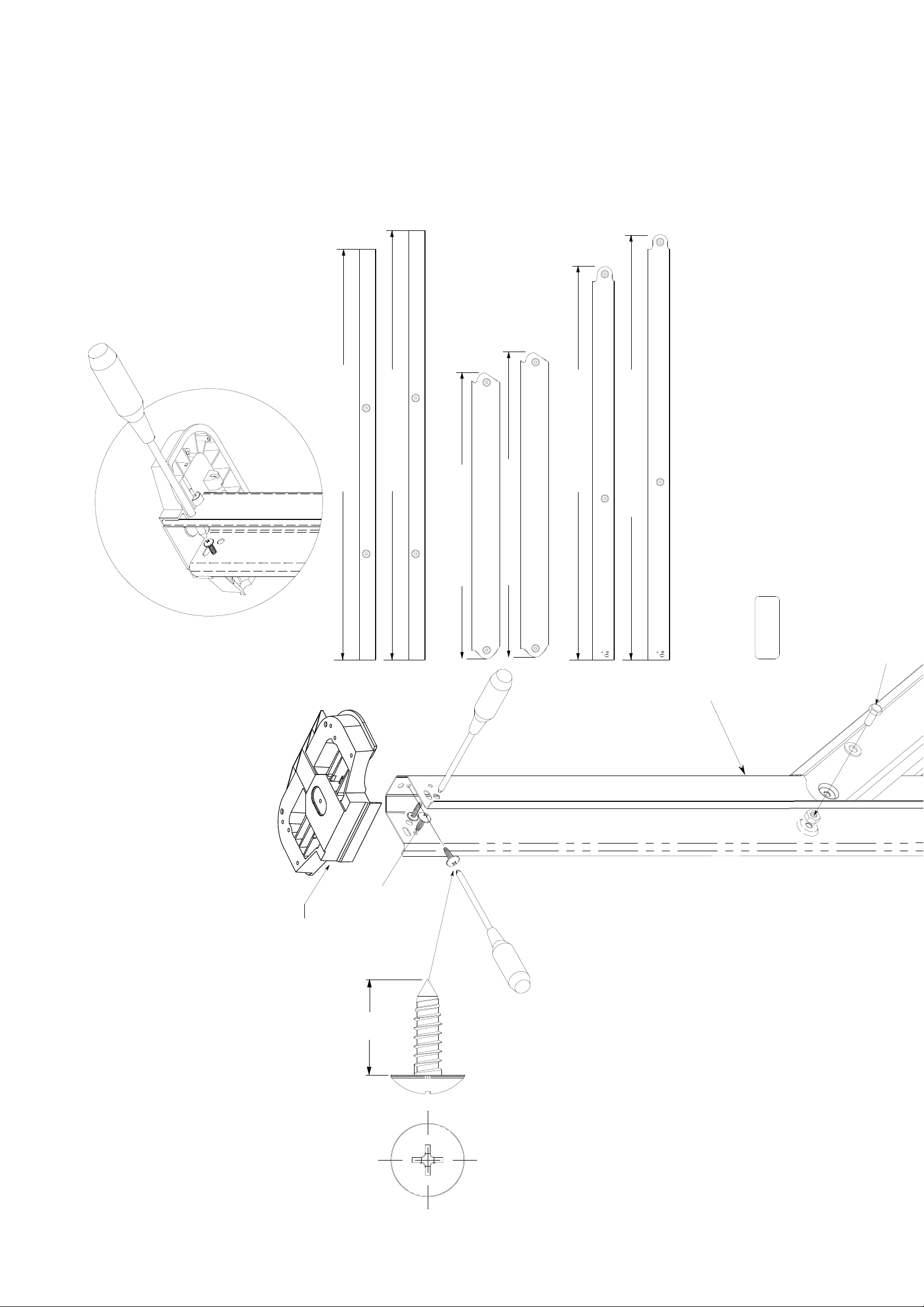
P.No.5239 Horizontal Support For 52"
P.No.5238 Horizontal Support For 48"
P.No.3313 Side Vertical For 48"
P.No.4106 Brace For 52"
P.No.4105 Brace For 48"
P.No.3314 Side Vertical For 52"
(1270mm)
4' 2"
(1321mm)
4' 4"
(1264mm)
4' 3/4"
(1367mm)
4' 5-7/8"
(920mm)
(980mm)
3' 1/4"
3' 2-5/8"
The Fi gure which look ed at attach ment of
Side Upper Jo int from down.
STEP2
M8 x 20 Hex Head Bolt
P.No.0923
P.No.3313 Side Vertical For 48"
P.No.3314 Side Vertical For 52"
3) ASSEMBLINGSIDE VERTICA L, HORIZONTAL SUPPORT A ND BRACE
Use #0104PACK Oval frame bolt package.
P.No.3177
Use #0105(#0106)PACK Strap bolt package.
from inside, Do not fasten tightly.
W asher from out side then put M8 nut
Connect side v er tical t o hor izontal support.
Put M8x20 hex head bolt with Plain
STEP1;
Connect brace to side verti cal.
W asher from out side then put M8 nut from i nsaide AND
Put M8x20 hex head bolt with Plain
STEP2;
1/4"X1/2" truss head screw from out side then
put 1/4" nut from inside, Do not f asten
Resin Side Upper Joint
(Packed #3 Package)
tightly.
3/4
#12 Sheet Metal Screw
P.No.0341
3
 Loading...