

Page 1
INSTALLATION AND USER INSTRUCTIONS
FOR THE DROP-IN COOKTOP
FOR THE HOME
MODELS RBCT304BSS and RBCT365BSS
THIS APPLIANCE WAS DESIGNED FOR EASE OF INSTALLATION AND OPERATION. HOWEVER, WE
RECOMMEND THAT YOU READ ALL SECTIONS OF THIS MANUAL BEFORE YOU BEGIN INSTALLATION. INSTALLATION MUST BE PERFORMED BY AN APPROVED GAS INSTALLER OR GAS SERVICE
TECHNICIAN OR THE WARRANTY IS VOID. IN THE COMMONWEALTH OF MASSACHUSETTS A
LICENSED PLUMBER OR GAS FITTER CAPABLE OF REVIEWING AND PERFORMING THE MANUFACTURER’S INSTALLATION CHECKLIST SHOULD INSTALL THIS APPLIANCE. THE INSTALLATION
CHECKLIST IS INCLUDED AT THE REAR OF THIS BOOKLET.
DO NOT REMOVE PERMANANTLY AFFIXED LABELS, WARNINGS OR DATA PLATES FROM YOUR
APPLIANCE. THIS MAY VOID THE MANUFACTURER’S WARRANTY AND/OR HINDER EFFECTIVE
SERVICING AND MAINTENANCE.
THESE INSTRUCTIONS ARE TO REMAIN WITH THE APPLIANCE AND THE CONSUMER IS TO RETAIN
THEM FOR FUTURE REFERENCE.
WARNING
If the information in this booklet is not followed
exactly, a fire or explosion may result causing
property damage, personal injury or death.
WHAT TO DO IF YOU SMELL GAS
Do not try to light any appliance
Do not touch or activate any electrical switch
Do not use any phone in your building
Immediately call your gas supplier from a neighbor’s house
Follow the gas supplier’s instructions
If you cannot reach your gas supplier, call the fire department
Installation and service must be performed by a qualified installer, service agency or gas supplier.
© Copyright 2010 Prizer –Painter Stoves Works
WARNING
Do not store or use gasoline or other flammable
vapors and liquids in the vicinity of this or any
other appliance.
P/N 751001 Rev 1
Page 2

Since 1880, we have been dedicated to quality! We believe that our success can only be
measured by the continuing success of our customers. We achieve customer satisfaction by
ensuring that each of our employees understands, meets and exceeds customer expectations.
We establish and maintain an environment that encourages all employees to pursue continuous improvement in quality and productivity.
Our quality policy is monitored by the highest levels of management.
We hope you enjoy your new appliance and we THANK YOU again for believing in our
product as much as we do.
The staff and team at Prizer!
All specifications are subject to change without prior notice
P/N 751001 Rev 1
Page 3

WELCOME
...to the exciting world of BlueStar™ cooking! You have purchased one of the finest appliances available for home
use, which shows that you take cooking seriously. As the owner of a new BlueStar appliance you can look forward
to years of cooking enjoyment. You will prepare meals with the speed and accuracy of a professional chef right in
your own kitchen! All equipment is designed and manufactured to the highest quality standards in the industry specifically to meet the needs of the world’s most demanding chefs: you. From simmering to sautéing, baking and
broiling these versatile appliances provide the flexibility you need in any cooking application. Commercial styling
adds a touch of elegance to your kitchen like no other appliance can. What’s more, this high quality, highperformance appliance is backed by our professional service network from coast to coast to provide you with
quick, competent technical service should the need arise. Please take a few moments now to fill in the information
below for your future reference. In the event you require parts or service, this information will be needed to ensure
you receive the highest quality service we can provide.
DATE OF PURCHASE
DEALER’S NAME
DEALER’S ADDRESS
DATE OF INSTALLATION
INSTALLER’S NAME
INSTALLER’S ADDRESS
MODEL NUMBER
SERIAL NUMBER
NOTE: WARRANTY SERVICE MUST BE PERFORMED BY AN AUTHORIZED SERCIVE AGENT. A LIST
OF THESE AGENTS MAY BE PROVIDED BY YOUR DEALER. YOU MAY ALSO REQUEST WARRANTY
SERVICE BY CALLING 610-376-7479.
In the Commonwealth of Massachusetts, gas connections must be
performed by a licensed plumber or licensed gas fitter.
P/N 751001 Rev 1
Page 4

TABLE OF CONTENTS
Introduction............................................................................................................................... 2
Welcome .................................................................................................................................. 3
Table of Contents...................................................................................................................... 4
Safety Instructions .................................................................................................................... 5
Site Preparation......................................................................................................................... 6
Installation Unpacking / Positioning......................................................................................... 7
Positioning ................................................................................................................................ 8
Gas Connections ....................................................................................................................... 8
Electrical Connections .............................................................................................................. 9
Ventilation................................................................................................................................. 9
Operation................................................................................................................................. 10
Cleaning .................................................................................................................................. 11
Troubleshooting ...................................................................................................................... 12
Electrode/Igniter Replacement……………………………………………………………….13
Warranty ................................................................................................................................14-15
Performance Checklist............................................................................................................16-18
All specifications are subject to change without prior notice
P/N 751001 Rev 1
Page 5

SAFETY INSTRUCTIONS
To avoid personal injury or property damage,
please read and follow these important safety
precautions.
1. Before any maintenance or repairs are performed, disconnect the appliance from the
electric supply.
2. Your appliance should be installed by a
qualified gas installation technician. Have
the technician show you the exact location
of the gas shutoff valve on the incoming
gas line so you know how to turn off the
gas if necessary.
3. In the event of a power failure, do not attempt to operate the appliance or light any
of the burners. This is a gas fired appliance
that employs electrical components such as
the ignition and safety devices.
4. Do not attempt to repair or replace any part
of this appliance unless specifically instructed to do so by this manual. Inwarranty service must be performed by an
authorized service agency.
5. Do not store flammable materials on or
near the appliance. Keep the appliance area
clean and free of combustible materials,
gasoline and other flammable vapors and
liquids. A check before each use to determine that no hazardous materials are in the
area is recommended.
6. The push-to-turn control knobs on this appliance are designed to be child-safe, however, not a guarantee of operation. Children
should not be left alone or unattended in the
kitchen while the appliance is in use.
7. Additional care should be exercised if your
appliance is equipped with a high-shelf.
During heavy or continued use this shelf
may become hot. Do not place combustible materials or plastics on this shelf.
8. Do not store items of interest to children
above the appliance. Children, as well as
adults, should never be allowed to sit,
stand, or climb on any part of the appliance. Serious injury may occur.
9. Never leave the appliance unattended during use. Boil-overs may occur, causing
spills which may ignite.
10. Do not use water on grease fires. Never
pick up a flaming pan. It is recommended
you purchase a multi-purpose dry chemical or foam-type fire extinguisher for your
home. Store it in close proximity to your
appliance.
11. If you are flaming liquor or other spirits,
and you appliance is installed under a vent
hood, TURN THE FAN OFF. The draft
created could cause the flames to spread
out of control.
12. For your safety, never use your appliance
or any other cooking appliance as a space
heater to warm or heat the room.
13. Use only dry potholders. Moist or damp
potholders on hot surfaces may result in
steam burns. Do not allow potholders to
touch hot burner areas. Do not use a towel
or other bulky material as a potholder.
14. To reduce the risk of burns, ignition of
flammable materials, and spillage, the
handle of any pot or pan should be positioned so that it does not extend over adjacent burners or the front of the appliance.
WARNING
Operation of this product could expose you to carbon monoxide if not adjusted properly. Inhalation of carbon monoxide is known to the state of California to cause birth defects or other reproductive harm.
P/N 751001 Rev 1
Page 6
SITE PREPARATION
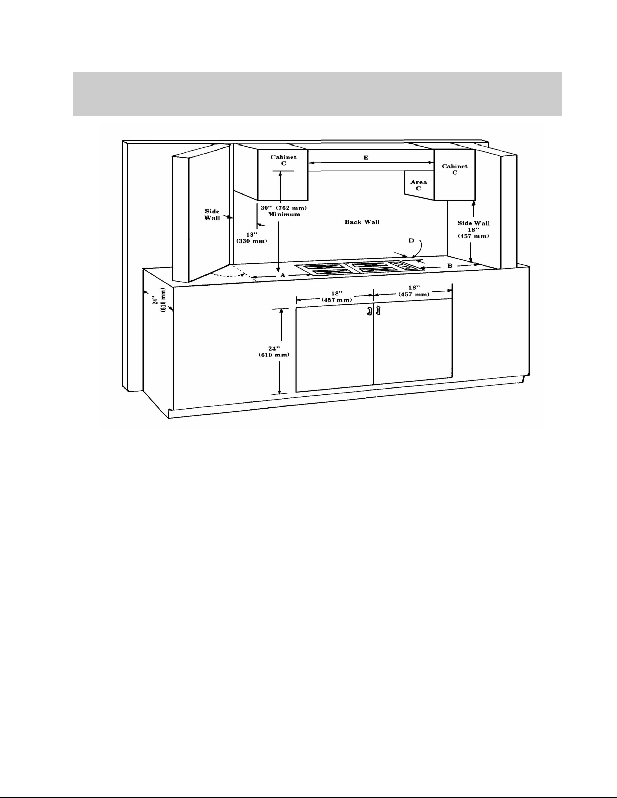
Your Drop-in Cooktop may be installed into a
counter top in a row of cabinets or into an island. Refer to the illustration above for key
dimensions to be followed when installing
your appliance.
Your cooktop has zero clearance requirements
to surrounding surfaces. There are restrictions
to flammable surfaces around and above
your cooktop. These minimum dimensions
are shown in the figure. Dimension “E” is for
your ventilation hood. It is recommended that
your exhaust hood be powerful enough to
move a minimum of 300 cfm.
Dimensions “A” and “B” must be a minimum
of 6” [150mm] from side walls or cabinets.
Dimension “D” must be at least 1
1/2” [38mm] from back wall to the cooktop.
All specifications are subject to change without prior notice
If installed in a countertop along a wall at the
rear the surface must be inflammable material
extending at least six inches upward.
When making the cut-out be sure to follow
the dimensions that match the body of your
cooktop model. The cut-out required is
smaller in both directions than the finished
top. The depth is always 20-1/4 inches. The
width is either 28-1/4 inches for a 30 in
cooktop or 34-1/4 inches for a 36 in cooktop.
THE FRONT FACE OF THE UNIT
MUST BE 2 (TWO) INCHES FROM
THE FRONTEDGE OF THE COUN-
P/N 751001 Rev 1
Page 7

INSTALLATION
UNPACKING
1. Check the package for damage. If any
damage is visible you should mark the bill
of lading you sign that there may be concealed damage.
2. Insure the container is upright. If the con-
tainer is not upright major damage can
occur to your appliance. If damage is discovered, do not refuse delivery. Contact
the carrier and file appropriate freight
claims. Do not contact the manufacturer.
Your appliance was shipped from the
dealer you purchased it from. Shipping
damage claims are to be resolved between
the customer, shipping carrier and dealer.
The manufacturer may assist in resolving
any such claims, but such assistance does
not relieve you of your responsibility.
3. Move the container as close to its installa-
tion location as possible. This will reduce
moving and handling your appliance once
it is out of its shipping container.
4. Cut the straps holding the carton to the
palette. Lift the box directly up and off
the appliance. Do not use a hammer. Do
not cut the carton with a razor, utility or
box cutting knife.
5. Thoroughly inspect your appliance for
damage. If damage is discovered, do not
refuse delivery. Contact the carrier and
file appropriate freight claims. Do not
contact the manufacturer. Your appliance
was shipped from the dealer you purchased it from. Shipping damage claims
are to be resolved between the customer,
shipping carrier and dealer. The manufacturer may assist in resolving any such
claims, but such assistance does not relieve you of your responsibility.
6. Remove and unpack any accessories
shipped with your appliance. Make sure
no hardware or accessories are left to be
disposed of unintentionally.
POSITIONING
1. The importance of the proper installation
of gas cooking equipment cannot be overstressed. Proper performance of the
equipment is dependent, in great part, on
the compliance of the installation with the
manufacturer’s specifications.
2. Each gas appliance shall be located with
respect to building construction and other
equipment to permit access to the appliance. Such access and clearance is necessary for cleaning and servicing.
3. Due to size and weight, a rolling lift jack,
air sled or pallet jack may be required to
move the appliance into position.
4. Do not push against the edges or sides of
any appliance in an attempt to slide it into
position. Although all metal parts are deburred during the manufacturing process,
serious injury could occur if the appliance
were to move suddenly while being positioned. We recommend you use gloves
during the installation process.
5. As part of the installation protective plastic wrappers on stainless steel surfaces
should be removed. These wrappers must
be removed before operation.
6. For optimum performance the appliance
should be leveled during installation. A
carpenter type level should be placed on
the appliance three ways: side to side,
front to back, diagonally.
7. Appliances on bullet legs may be leveled
by screwing the various leg assemblies in
or out. If the appliance is for installation
in an island or cabinet cut-out the edges
should be shimmed with small metal coupons.
The appliance must be installed
by a licensed gas technician or
appliance installer
P/N 751001 Rev 1
Page 8

INSTALLATION
GAS CONNECTIONS
1. The installation of this appliance must
conform with all applicable local codes.
In the absence of local codes, the installation must conform to the latest level of the
National Fuel Gas Code, ANSI Z223.1/
NFPA 54. In Canada, the installation
must be in accordance with the current
CAN/CGA B149.1 and B149.2.
2. This appliance is designed to work with
either natural gas or LP gas. Verify that
the appliance and the incoming gas supply
are compatible. Check the rating plate.
3. The gas supply line must be the same size
or larger than the gas inlet of the appliance. Your appliance has either a ½”
NPT or ¾” NPT gas inlet connection. We
recommend the supply line be ¼” NPT
larger than the gas inlet of the appliance.
4. Sealant used on pipe joints must be resistant to LP gas.
5. An installer provided manual shut-off
valve must be installed in the gas supply
line ahead of the appliance. This shoutoff must be easily accessible in case of
emergency.
6. All gas cooking equipment must have a
pressure regulator on the incoming service
line for safe and efficient operation. This
appliance is equipped with such a gas
pressure regulator. Incoming gas pressure
should be checked with a manometer.
The correct manifold pressure for natural
gas is 5.0” wc. For LP gas the correct
manifold pressure is 10” wc.
7. Incoming line pressure upstream of the
appliance should be 1.0” wc greater than
the operating manifold pressure. Service
pressure may fluctuate for a variety of reasons. Under no circumstances should the
factory installed regulator be removed or
by-passed.
8. The factory installed pressure regulator
will withstand an input pressure of ½ PSI
(12” wc). If the incoming pressure exceeds the maximum rating a step-down
regulator is required.
9. The appliance and it individual shut-off
valve must be disconnected from the gas
supply line during any pressure testing in
excess of ½ PSI [3.5 kPa].
10. The appliance must be disconnected from
the gas supply by closing its individual
shut-off during any pressure testing less
than ½ PSI [3.5 kPa].
11. Check to see that all installer –supplied
pipes and fittings are clear of direct,
threading chips or other foreign particles
before connecting the appliance to the
supply line. Such particles will clog orifices and/or valves when pressure is applied. Service to clean such clogs is not
covered by your warranty.
12. The incoming gas supply is brought from
the inlet pipe. This is the only connection
required via the installer-supplied shut-off
valve.
13. If the appliance is to be installed with
flexible couplings and/or a “quick disconnect” the installer must use a commercially approved AGA Design certified flexible connector at least ½” NPT that complies with ANSI Z21.41. In Canada the
connector must comply with CAN 16.1088 and the “quick disconnect” device
must comply with CAN 16.19M-79 and
installed with a strain relief device.
14. Before putting the appliance into service
test all gas connections for leaks. Use a
soapy solution. DO NOT USE AN OPEN
FLAME TO CHECK FOR LEAKS. Such
a procedure is dangerous and it may not
detect all the small leaks that a soapy solution will.
15. Air shutter adjustments are preset at the
factory. These adjustments may need to
All specifications are subject to change without prior notice
P/N 751001 Rev 1
Page 9

INSTALLATION
be redone and/or fine tuned by the installer. These adjustments are the responsibility of the installer and are not covered by
your warranty.
16. A gas conversion performed in the field
may void your warranty. Contact your
dealer for information regarding the conversion from one type of gas supply to
another.
ELECTRICAL CONNECTIONS
1. The installation of this appliance must
conform with all applicable local codes.
In the absence of local codes, the installation must conform to the latest level of the
National Electric Code, ANSI/NFPA 70.
2. This appliance is equipped with a standard
three prong polarized, NEMA 5-15P line
cord to be plugged into a 120Volt 15 Amp
outlet.
3. Removing the grounding prong from the
plug will void the manufacturer’s warranty.
4. The cord exits the appliance
5. If the electrical supply is not turned on or
is interrupted the appliance will not operate.
6. The applicable wiring diagram for this
appliance is affixed to the appliance.
7. The circuit where you plug your appliance
must be grounded and polarized.
8. We recommend the circuit for your appliance be a dedicated line.
9. It is recommended that your circuit never
include a microwave oven.
10. If present, an optional rotisserie motor is
also equipped with the same grounded
plug.
WARNING
This appliance is equipped with a threepronged grounding plug for your protection against shock hazard and should be
plugged directly into a properly grounded
receptacle. Do NOT cut or remove the
grounding prong from this plug.
If the appliance is not grounded or its polarity is reversed severe shock hazards can
exist.
If present, the optional rotisserie motor
must be also be grounded in accordance
with local codes or in the absence of local
codes with the National Electric Code ANSI/NFPA 70.
VENTILLATION
Proper ventilation is highly important for
good operation. This appliance must be installed under a properly designed canopy
hood. The width of the hood can be the same
as the cooking unit, but we recommend the
hood be 6” wider for optimal performance.
A strong exhaust fan can create a vacuum in
the room. For proper air balance work with
your dealer and/or contactor to properly size
your hood and its exhaust fan. A minimum of
300 cfm’s is recommended for both the 30”
and 36” models.
All gas burners need sufficient air to operate
and large objects should not be placed in front
of this appliance or obstruct the airflow
through the front covers. Do not place objects over the rear vent exit.
IMPORTANT
ALL GAS BURNERS NEED SUFFICIENT
AIR TO OPERATE AND LARGE OBJECTS
SHOULD NOT BE PLACED IN FRONT OF
THIS APPLIANCE WHICH WOULD OBSTRUCT THE AIR FLOW THROUGH THE
FRONT. OBJECTS SHOULD NOT BE
PLACED ON THE REAR BACKGUARD
P/N 751001 Rev 1
WHILE IN USE. THIS COULD OBSTRUCT THE VENTING SYSTEM OF
Page 10

OPERATION
GENERAL
As part of the installation protective plas-
tic wrappers on stainless steel surfaces
should be removed. These wrappers must
be removed before operation.
New appliances are wiped clean with vari-
ous cleaners and solvents to remove visible signs of dirt, oil and grease before
leaving the factory. During the initial
start-up, after performance checks and
adjustments, the appliance should be allowed to heat for about 30 minutes to burn
off any such oils from internal parts. The
presence of such coatings is normal as
part of the manufacturing process. The
ventilation hood should be turned on and
the area well ventilated to allow fumes to
escape safely.
Removable parts should be washed with
hot soapy water, well rinsed and wiped
dry.
BURNERS
Remove the ring grates and top grates and
thoroughly wash them with hot soapy water, rinse and wipe dry. Extended exposure to moisture may cause these cast
parts to rust.
To light a burner turn the corresponding
control knob to HIGH.
This knob is a gas control valve and an
electric switch. Turning to the High position begins the ignition sequence.
The igniters begin to “click”. As gas
flows through the piping to the burner the
sparking ignites it. After the flame lights
the igniter senses its heat and the
“clicking” automatically stops.
ALL burners light at the HIGH setting.
Burners are equipped with a re-ignite fea-
ture in case the flame is extinguished for
any reason.
At the High setting, flames should be ap-
proximately ½ inch high, with a sharp
blue tip. Some yellow may appear depending on the type of gas being burned.
Adjust the flame so it does not wrap
around the bottom edge of the pan.
Burners may be operated at any knob po-
sition between LOW and HIGH.
Never operate the burner with the know
between the HIGH and OFF position. If
the flame goes out it will not re-ignited
and gas leaks could occur.
NEVER use this appliance as a space
heater to heat or warm the room. Doing
so may result in carbon monoxide poisoning and over-heating of the oven.
All specifications are subject to change without prior notice
P/N 751001 Rev 1
Page 11

CLEANING
BODY
All stainless steel and painted parts should
be cleaned regularly with hot soapy water.
Commercially available stainless steel
cleaners may be use don stainless steel.
Be sure to follow manufacturer’s instruction for use.
Do NOT use steel wool or metal pads or
other abrasive cleaners. These surfaces
are painted or polished and using these
product will scratch and damage your finish.
In extreme conditions use a cloth soaked
in hot water to sit on the soiled area to
soften the residue and allow it to be safely
cleaned off. LIGHT scraping with a rubber or nylon spatula may be used to finish
lifting residue off.
Do NOT use a metal knife, spatula or sim-
ilar or any metal tool to scrape these surfaces.
Do NOT permit citrus or tomato juices to
sit and dry on these surfaces. Wipe such
spills immediately. Citric acid will discolor stainless steel.
BURNERS
The ring grates and top grates of your ap-
pliance may be effectively cleaned with
ho soapy water.
In the event of heavy soiling, a commer-
cially available oven cleaner may be safely used on these parts. Be sure to follow
the manufacturer’s instructions for use.
Insure the cleaning chemical does not
contact any painted surfaces on your appliance.
To insure proper fit and safe use replace
the top grates and ring grates in their
proper position. Ridges and ledges allow
the parts to fit together aligned properly.
The grease drip pan may be pulled out for
cleaning. Removing the pan from the appliance is possible but usually not necessary.
P/N 751001 Rev 1
Page 12
TROUBLESHOOTING
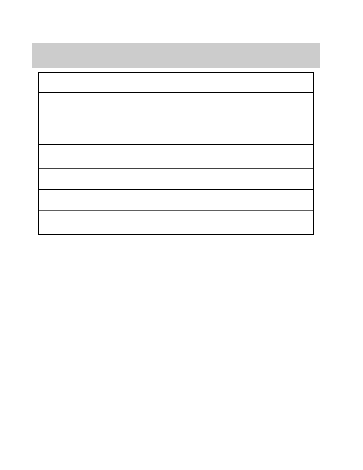
Burner won’t light—no “clicking” from igniter Insure appliance is plugged in
Insure circuit is not tripped or fuse blown
Burner won’t light—”clicking”, no flame Insure gas is turned on
Insure burner ports are clean
Try a second burner for same or different result
Insure electrode is plugged in
Insure electrode is properly lined up
Insure electrode is not cracked—spark not in correct
place
Burner lights, “clicking” won’t stop Insure electrode wires are properly connected after
cleaning
Call for service
LAZEY flame—floating, larger in size than normal Air shutter adjustment
LIFTING flame—well defined with visible inner core,
noisy, gap between burner and flame
Pungent odor when burners on Insure burner is properly seated after cleaning
Air shutter adjustment
Check for lazy flame
All specifications are subject to change without prior notice
P/N 751001 Rev 1
Page 13
Igniter / Electrode replacement
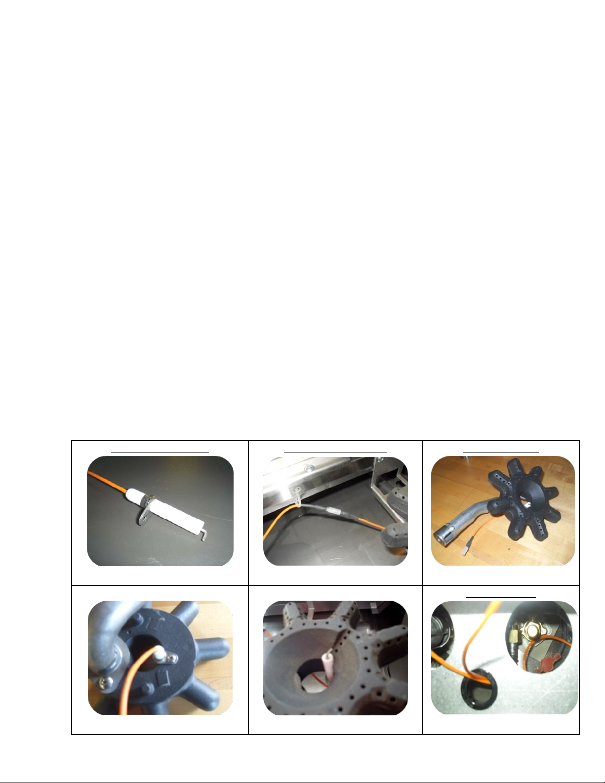
The following procedure is required to replace any top burner igniter. A Phillips head screwdriver is
required.
1. Shut off the gas & power to the product.
2. Remove the ring grate & the square bowl grate associated with the igniter in question of replacing.
For rear burner igniter replacement, also remove the grates on the front burner.
3. Disconnect the orange lead wires (picture 2)
4. Remove the burner assembly (burner head & connected venturi tube, picture 3) by pulling upward
then back to free the assembly from its position.
5. Remove the igniter by removing the screw that holds the igniter to the burner head with a Phillips
head screwdriver (picture 4).
6. Install the new igniter securely to the burner head in proper alignment (picture 5).
7. Reinstall the burner assembly.
a. Lean over and look inside to locate the round brass orifice, which is where the gas enters.
b. Be sure when reinstalling venturi (burner tube connected to burner head) that the end fits
over the brass orifice. (picture 6)
c. Make sure burner head sits level with the two prongs on the bottom of the burner head
through the holes on the burner support.
8. Connect the lead wires. Wires should be under the burner supports, not pinched between burner
head and the support. Make sure the wires are not resting on drip pan.
9. Test the unit for proper operation.
Igniter – Part # 741801
Picture 1
Igniter Screw Location
Lead Wires Connection
Picture 2
Igniter Alignment
Burner Assembly
Picture 3
Orifice Location
Picture 4
Picture 5
P/N 751001 Rev 1
Picture 6
Page 14

WARRANTY
WHAT IS COVERED?
Prizer-Painter provides the following limited warranties to the original retail purchasers of Products sold and
installed in the continental United States and Canada on or after February 22, 2002. The appliance must be
installed by a certified gas technician or license plumber for any warranty authorizations. Self installations
will void any/all warranty.
Initial Seven (7) Day Limited Warranty. Prizer-Painter warrants that all cosmetic components of its
Products will, under normal use and service, be free from defects in materials and workmanship for a period
of seven (7) calendar days from the date of delivery (the "Warranty Period") to the original retail purchaser.
For purposes of this Limited Warranty, cosmetic components include top grates, ring grates, plate rail, kick
panel, body sides, glass, control panel, door panel, back guards, oven seals, light bulbs, and enameled parts.
All warranty claims for cosmetic items must be reported immediately within seven calendar days of delivery
or such claims will not be honored. Please refer to your installation checklist to activate your limited warranty.
One (1) Year Limited Warranty. Prizer-Painter warrants that all functional components (except cast iron
burner tops) of its Products will, under normal use and service, be free from defects in materials and workmanship for a period of one (1) year from the date of delivery (the "Warranty Period") to the original retail
purchaser. For purposes of this Limited Warranty, functional components include all components of the
Product other than the cosmetic components covered by the initial seven day limited warranty and the cast
iron burner tops covered by the 10 year limited warranty. Floor models are not covered under the One(1)
Year Limited Warranty but are covered by a Ninety (90) Day Labor and a one (1) Year Limited Parts Warranty with proof of date of install and a completed Installation Checklist. Demonstration units are not covered under the one (1) Year Limited Warranty. Please refer to your installation checklist to activate your
limited warranty. Failure to send a complete and accurate copy of the installation checklist within 15
days of installation will invalidate your limited warranty.
Ten (10) Year Limited Warranty. Prizer-Painter warrants that all functional components of its cast iron
burner tops will, under normal use and service, be free from defects in materials and workmanship for a period of ten (10) years from the date of delivery (the "Warranty Period") to the original retail purchaser. Please
refer to your installation checklist to activate your limited warranty. Failure to send a complete and accu-
rate copy of the installation checklist within 15 days of installation will invalidate your limited warranty.
If any Product fails to comply with the foregoing Limited Warranties during the applicable Warranty Period,
Prizer-Painter will, at its option, either (i) pay the reasonable labor and material costs to have the Product
repaired by a factory authorized service agent; (ii) replace the Product or defective component of the Product; or (iii) if in Prizer-Painter's sole judgment circumstances are such as to preclude the remedying of any
breach of warranty by repair or replacement, then Prizer-Painter will refund the purchase price paid by the
original purchaser. All repairs or replacement service must be performed by a factory authorized service
agent. Additionally, all Products must be accessible for service in the home and must be accessible via public highways within 100 miles roundtrip of a factory authorized service agent. The purchaser will be responsible for the cost of additional mileage, non-standard service and special equipment to remove the Product
for service so that there is accessibility on all sides of the Product.
The repair or replacement of the Product or the return of the purchase price will be the purchaser's sole and
exclusive remedy for any breach of this Limited Warranty or any other claim with respect to the Product,
including those claims based on contract, warranty, or tort. In no event will Prizer-Painter's liability for any
defective Product exceed the purchase price thereof. This exclusive remedy will not be deemed to have
failed of its essential purpose so long as Prizer-Painter is willing and able to repair and/or replace defective
Products in the manner prescribed herein or to provide a refund if, in Prizer-Painter's sole judgment, repair
or replacement is not feasible or appropriate under the circumstances.
All specifications are subject to change without prior notice
P/N 751001 Rev 1
Page 15

WARRANTY
WHAT IS NOT COVERED?
This Limited Warranty is the sole and exclusive warranty provided for the Product and extends only to original retail purchasers in the continental United States and Canada. This Limited Warranty is not transferable
to any subsequent purchasers or users. If any implied warranties arise under any applicable law (including,
but not limited to, implied warranties of merchantability and fitness for particular purpose), then the duration
of those implied warranties will last only as long as the express warranties stated above. Prizer-Painter will
not under any circumstances be liable for any special, indirect, incidental or consequential damages of
any kind, including but not limited to loss of business or profits, loss of use, or installation or removal
costs. Nor will Prizer-Painter be responsible for any shipping costs related to the repair or replacement of
any Product under this Limited Warranty. Some States do not allow the exclusion or limitation of incidental
or consequential damages or limitations on how long implied warranties last, so the above limitations may
not apply to you.
This Limited Warranty does not apply to commercial usage or to any Products installed in any nonresidential settings such as day cares, bed and breakfasts, hotels, nursing homes, churches, etc. This Limited
Warranty also does not cover, and specifically excludes, chipping porcelain, porcelain igniters, calibrations
and normal adjustments after installation and setup, burner adjustments, normal care and maintenance,
cleaning of parts, shipping damage, discoloration of the griddle, rust, gasket materials, ceramic materials,
and fuses. Additionally, there is no warranty coverage for any Products that fail or have been damaged due
to alterations or modifications; abuse; misuse; neglect; improper installation, instruction, handling, operation, maintenance or storage; accidental or intentional damage; normal wear and tear; unauthorized service
or repairs, including unauthorized adjustments or calibrations performed on the Product; damage from natural disasters, fires, floods, earthquakes or other acts of God; loss of electrical power to the Product for any
reason; alteration for outdoor use; damage due to the use of harsh chemicals (e.g., cleaning products improperly applied); or any other circumstances beyond Prizer-Painter's control. This Limited Warranty is also invalid if the original factory installed serial number has been altered or removed from the Product.
The Purchaser is responsible for proper installation and normal care and maintenance of the Product. This
warranty gives you specific legal rights, and you may also have other rights which vary from State to State.
OBTAINING WARRANTY SERVICE
All warranty claims must be reported to Prizer-Painter Stove Works, Inc., 600 Arlington St., Reading, Pennsylvania 19611 prior to the expiration of the applicable Warranty Period. If a warranty claim relates to cosmetic parts, any such claim must be reported to Prizer-Painter within seven (7) calendar days after the Product has been delivered. The purchaser must call the factory at the toll free 1-800-449-8691 to report a warranty claim or to obtain information about warranty service. If any warranty claim is not submitted as required by this Limited Warranty, any such claim will be invalid and will not be honored. At the time the
warranty claim is made, the purchaser must provide the model number of the Product, the serial number of
the Product, proof of delivery, signed installation receipt , a description of the claimed defect, and proof of
purchase of the Product, including the original retail receipt or invoice to establish the Warranty Period.
Prizer-Painter must also be given an opportunity to inspect any defective Product.
All warranty repairs must be performed by a factory authorized service agent. Service will be provided during normal business hours. The purchaser will be responsible for any labor performed at overtime or premium rates. The purchaser is also responsible for making the Product accessible for service.
P/N 751001 Rev 1
Page 16

PERFORMANCE CHECKLIST
This checklist has been developed to assure proper installation of your appliance
To validate your warranty you must mail or fax this form and a copy of your receipt to:
Warranty Department, Prizer-Painter, 600 Arlington Street, Reading, PA 19611, Fax (610) 376-2596
Customer Information (Please Print) Product Information (Please Print)
Name:________________________________________ Model No: ________________________________
Address: ______________________________________ Serial No: _________________________________
City: _________________________________________ Purchase Date: _____________________________
State, Zip Code: ________________________________ Installation Date: ___________________________
e-mail: _______________________________________ Installer’s Name: ___________________________
Telephone: ____________________________________ Company: _________________________________
Dealer: _______________________________________ Telephone: ________________________________
CHECK ALL THAT APPLY
Appearance and Aesthetics Electrical Connection
Exterior Correct voltage
Top section Grounded outlet
Oven interior Polarized outlet
Broiler pan set No GFCI
Installation Gas Connection
Proximity to cabinets Verify fuel—_____Nat _____LP
Level Gas shut-off present and accessible
Backguard in place Supply line properly sized
Ventilation system Supply pressure checked
Read User Manual Operating pressure checked
Review safety instructions All connections checked for leaks
Ignition Flame Adjustment Air/Gas Mixture Valve Operation
Top Burners Top Burners Top Burners Top Burners
Griddle Griddle Griddle Griddle
Char Broiler Char Broiler Char Broiler Char Broiler
Oven Burner Oven Burner Oven Burner Oven Burner
Infrared Broiler Infrared Broiler Infrared Broiler Infrared Broiler
Controls Oven Door
Burner knobs Alignment
Thermostats Door seal
Convection oven fan & switch Hinges
Oven light switch
All specifications are subject to change without prior notice
P/N 751001 Rev 1
Page 17

Fold Here
———————————————————————————————————————————————
____________________________
_______________________________
_______________________________
Prizer-Painter Stove Works, Inc.
600 Arlington Street
Reading, PA 19611
**Performance Checklist Enclosed**
———————————————————————————————————————————————
Fold Here
P/N 751001 Rev 1
Page 18

PERFORMANCE CHECKLIST
This checklist has been developed to assure proper installation of your appliance
To validate your warranty you must mail or fax this form and a copy of your receipt to:
Warranty Department, Prizer-Painter, 600 Arlington Street, Reading, PA 19611, Fax (610) 376-2596
Customer Information (Please Print) Product Information (Please Print)
Name:________________________________________ Model No: ________________________________
Address: ______________________________________ Serial No: _________________________________
City: _________________________________________ Purchase Date: _____________________________
State, Zip Code: ________________________________ Installation Date: ___________________________
e-mail: _______________________________________ Installer’s Name: ___________________________
Telephone: ____________________________________ Company: _________________________________
Dealer: _______________________________________ Telephone: ________________________________
CHECK ALL THAT APPLY
Appearance and Aesthetics Electrical Connection
Exterior Correct voltage
Top section Grounded outlet
Oven interior Polarized outlet
Broiler pan set No GFCI
Installation Gas Connection
Proximity to cabinets Verify fuel—_____Nat _____LP
Level Gas shut-off present and accessible
Backguard in place Supply line properly sized
Ventilation system Supply pressure checked
Read User Manual Operating pressure checked
Review safety instructions All connections checked for leaks
Ignition Flame Adjustment Air/Gas Mixture Valve Operation
Top Burners Top Burners Top Burners Top Burners
Griddle Griddle Griddle Griddle
Char Broiler Char Broiler Char Broiler Char Broiler
Oven Burner Oven Burner Oven Burner Oven Burner
Infrared Broiler Infrared Broiler Infrared Broiler Infrared Broiler
Controls Oven Door
Burner knobs Alignment
Thermostats Door seal
Convection oven fan & switch Hinges
Oven light switch
MAIL-IN COPY
All specifications are subject to change without prior notice
P/N 751001 Rev 1
 Loading...