

Page 1

INSTALLATION, USE AND CARE MANUAL
FOR PROFESSIONAL VENTILLATION FOR
THE HOME
MODELS: BS-PL SERIES, BS-PC SERIES
IMPORTANT!—PLEASE READ AND FOLLOW
1. THIS APPLIANCE WAS DESIGNED FOR EASE OF INSTALLATION AND OPERATION. HOWEVER, WE
RECOMMEND THAT YOU READ ALL SECTIONS OF THIS MANUAL BEFORE YOU BEGIN INSTALLA-
TION.
2. DO NOT REMOVE PERMANANTLY AFFIXED LABELS, WARNINGS OR DATA PLATES FROM YOUR
APPLIANCE. THIS MAY VOID THE MANUFACTURER’S WARRANTY AND/OR HINDER EFFECTIVE
SERVICING AND MAINTENANCE.
3. THESE INSTRUCTIONS ARE TO REMAIN WITH THE APPLIANCE AND THE CONSUMER IS TO RE-
TAIN THEM FOR FUTURE REFERENCE.
4. PLEASE OBSERVE ALL LOCAL AND NATIONAL BUILDING CODES AND ORDINANCES. IF NO LO-
CAL CODES ARE APPLICABLE, PLEASE FOLLOW ALL WIRING REQUIREMENTS IN ACCORDANCE
WITH THE NATIONAL ELECTRICAL CODE, ANSI/NFPA 70 EDITION.
5. PLEASE CHECK WITH A QUALIFIED AND TRAINED INSTALLER OR YOUR LOCAL CODES FOR ANY
MAKE UP AIR REQUIREMENTS.
6. THIS HOOD IS FOR RESIDENTIAL USE ONLY AND IS NOT DESIGNED FOR INSTALLATION OVER A
COMMERCIAL PRODUCT.
7. MAKE SURE ALL POWER IS TURNED OFF AT THE MAIN BREAKER OR FUSE BOX BEFORE MAKING
ANY CONNECTIONS.
8. TO AVOID RISK OF FIRE , ELECTRIC SHOCK, OR INJURY TO PERSONS, TURN OFF THE ELECTRICI-
TY TO THE HOOD FROM THE POWER SUPPLY BEFORE CLEANING OR SERVICING.
This product is intended for domestic use only!
© Copyright 2007 Prizer –Painter Stoves Works
P/N 750301 Page 1
Page 2
TABLE OF CONTENTS
Table of Contents ................................................................................................................................... 2
Safety Instructions ............................................................................................................................... 3-4
Introduction ............................................................................................................................................ 5
Welcome ................................................................................................................................................ 6
Handling & Unpacking .......................................................................................................................... 7
Packing list for your Vent Hood ....................................................................................................... 8-9
Pro Line Hoods ......................................................................................................................... 8
Pyramid Style Hoods ............................................................................................................... 9
Installation of Pro Line Series
Dimensions…………. .. ……………………………………………………………………10
Site Preparation …………………………………………………………………………….. 11
The Correct Height …………………………………………………………………………...12
Duct Information ……………………………………………………………………………..13
Blower Installation …………………………………………………………………………...14
Custom Duct Installation ……………………………………………………………………..15
Installation of Pyramid Style
Dimensions ............................................................................................................................. 16
Site Preparation .................................................................................................................... 17
The Correct Height ................................................................................................................ 18
Duct Information ................................................................................................................... 19
Blower Installation ................................................................................................................ 20
Flue Installation ..................................................................................................................... 21
Wire Diagram ..................................................................................................................................... 22
Cleaning and Maintenance ................................................................................................................. 23
Warranty .......................................................................................................................................... 24-25
Performance Checklist .................................................................................................................... 26-27
P/N 750301 Page 2
Page 3
IMPORTANT!—PLEASE READ AND FOLLOW
1. THIS APPLIANCE WAS DESIGNED FOR EASE OF INSTALLATION AND OPERATION. HOWEVER, WE
RECOMMEND THAT YOU READ ALL SECTIONS OF THIS MANUAL BEFORE YOU BEGIN INSTALLA-
TION.
2. DO NOT REMOVE PERMANANTLY AFFIXED LABELS, WARNINGS OR DATA PLATES FROM YOUR
APPLIANCE. THIS MAY VOID THE MANUFACTURER’S WARRANTY AND/OR HINDER EFFECTIVE
SERVICING AND MAINTENANCE.
3. THESE INSTRUCTIONS ARE TO REMAIN WITH THE APPLIANCE AND THE CONSUMER IS TO RE-
TAIN THEM FOR FUTURE REFERENCE.
4. PLEASE OBSERVE ALL LOCAL AND NATIONAL BUILDING CODES AND ORDINANCES. IF NO LO-
CAL CODES ARE APPLICABLE, PLEASE FOLLOW ALL WIRING REQUIREMENTS IN ACCORDANCE
WITH THE NATIONAL ELECTRICAL CODE, ANSI/NFPA 70 EDITION.
5. PLEASE CHECK WITH A QUALIFIED AND TRAINED INSTALLER OR YOUR LOCAL CODES FOR ANY
MAKE UP AIR REQUIREMENTS.
6. THIS HOOD IS FOR RESIDENTIAL USE ONLY AND IS NOT DESIGNED FOR INSTALLATION OVER A
COMMERCIAL PRODUCT.
7. MAKE SURE ALL POWER IS TURNED OFF AT THE MAIN BREAKER OR FUSE BOX BEFORE SERVIC-
ING OR MAKING ANY CONNECTIONS.
8. TO AVOID RISK OF FIRE , ELECTRIC SHOCK, OR INJURY TO PERSONS, TURN OFF THE ELCTRICITY
TO THE HOOD FROM THE POWER SUPPLY BEFORE CLEANING OR SERVICING.
WARNING!
TO REDUCE RISK OF FIRE, ELECTRIC SHOCK, OR
INJURY TO PERSONS, OBSERVE THE FOLLOW-
ING:
USE THIS UNIT IN THE MANNER INTENDED
BY THE MANUFACTURER, IF YOU HAVE
ANY QUESTIONS PLEASE CALL 610.374.7679
BEFORE CLEANING OR SERVICING UNIT,
SWITCH POWER OFF TO THE UNIT AT THE
SERVICE PANEL AND LOCK OUT THE SER-
VICE PANEL. IF THE SERVICE PANEL CAN-
NOT BE LOCKED OUT, PLEASE AFIX A
WARNING DEVICE PROMINENTLY, SUCH AS
A TAG, TO THE SERVICE PANEL.
WARNING!
TO REDUCE THE RISK OF A RANGETOP GREASE
FIRE:
NEVER LEAVE THE APPLIANCE UNATTEND-
ED DURING USE. BOIL-OVERS MAY OCCUR,
CAUSING SPILLS WHICH MAY IGNITE.
DO NOT USE WATER ON GREASE FIRES.
NEVER PICK UP A FLAMING PAN. IT IS REC-
OMMENDED YOU PURCHASE A MULTI-
PURPOSE DRY CHEMICAL OR FOAM-TYPE
FIRE EXTINGUISHER FOR YOUR HOME.
STORE IT IN CLOSE PROXIMITY TO YOUR
APPLIANCES.
TO REDUCE THE RISK OF A RANGETOP GREASE
FIRE (CONTINUED):
WARNING!
TO REDUCE RISK OF FIRE, ELECTRIC SHOCK, OR
INJURY TO PERSONS, OBSERVE THE FOLLOW-
ING:
INSTALLATION WORK AND ELECTRICAL
WORK MUST BE PERFORMED BY QUALIFIED
INDIVIDUALS IN ACCORDANCE WITH ALL
APPLICABLE CODES AND STANDARDS, IN-
CLUDING ALL FIRE RATED CONSTRUCTION
DO NOT DAMAGE ANY EXISTING ELECTRI-
CAL OR HIDDEN UTILITIES WHEN DRILL-
ING , CUTTING AND/OR REMOVING A WALL,
CEILING OR FLOOR
DUCTED FANS MUST VENT OUTDOORS
SUFFICIENT AIR IS REQUIRED TO PROPERLY
EXHAUST GASES THROUGH THE FLUE OF
NATURAL AND LIQUID PROPANE FUELED
COOKING EQUIPMENT TO AVOID ANY BACK
DRAFTING. FOLLOW ALL LOCAL AND NA-
TIONAL CODES AND STANDARDS FOR PROP-
ER AIR REQUIREMENTS.
USE ONLY METAL DUCTWORK
NEVER VENT DUCTED EXHAUST AIR INTO
ANOTHER ROOM OR GARAGE. TO REDUCE
THE RISK OF FIRE AND TO PROPERLY VENT
EXHAUST AIR, DUCT MUST VENT OUT-
DOORS
MATERIAL IN THIS MANUAL IS FOR REFER-
ENCE ONLY. DUE TO CONTINUOUS IM-
PROVEMENT THE MANUAL MAY DIFFER
FROM ACTUAL PRODUCT.
P/N 750301 Page 3
Page 4
WARNING!
IF YOU ARE FLAMING LIQUOR OR OTHER SPIRITS, AND YOUR APPLIANCE IS INSTALLED UNDER
A VENT HOOD, TURN THE FAN OFF. THE DRAFT CREATED COULD CAUSE THE FLAMES TO
SPREAD OUT OF CONTROL.
FOR YOUR SAFETY, NEVER USE YOUR APPLIANCE OR ANY OTHER COOKING APPLIANCE AS A
SPACE HEATER TO WARM OR HEAT THE ROOM.
USE ONLY DRY POTHOLDERS. MOIST OR DAMP POTHOLDERS ON HOT SURFACES MAY RESULT
IN STEAM BURNS. DO NOT ALLOW POTHOLDERS TO TOUCH HOT BURNER AREAS. DO NOT USE
A TOWEL OR OTHER BULKY MATERIAL AS A POTHOLDER.
TO REDUCE THE RISK OF BURNS, IGNITION OF FLAMMABLE MATERIALS, AND SPILLAGE, THE
HANDLE OF ANY POT OR PAN SHOULD BE POSITIONED SO THAT IT DOES NOT EXTEND OVER
ADJACENT BURNERS OR THE FRONT OF THE APPLIANCE.
CLEAN VENTILATING FANS AND GREASE BAFFLES OFTEN. GREASE SHOULD NOT BE ALLOWED
TO ACCUMULATE .
ALWAYS TURN HOOD ON WHEN OPERATING YOUR COOKING EQUIPMENT
WARNING!
TO REDUCE RISK OF INJURY TO PERSONS DUE TO A GREASE FIRE:
SMOTHER THE FLAMES WITH A CLOSE FITTING LID, COOKIE SHEET OR METAL TRAY, THEN
TURN OFF THE BURNER. TAKE CARE TO AVOID AND PREVENT BURNS. IF FLAMES DO NOT EX-
TINGUISH, EVACUATE THE PRMISES AND CALL THE FIRE DEPARTMENT
NEVER HANDLE OR PICK UP A FLAMING PAN.
DO NOT USE WATER, INCLUDING WET DISHCLOTHS, OR TOWELS. A VIOLENT STEAM EXPLO-
SION MAY ENSUE
DO NOT TURN ON HOOD TO EVACUATE SMOKE. TURN OFF HOOD
USE AN EXTINGUISHER ONLY IF:
YOU HAVE A CLASS ABC EXTINGUISHER AND YOU CAN OPERATE IT
THE FIRE IS SMALL AND CONTAINED WHERE IT STARTED
THE FIRE DEPARTMENT HAS BEEN NOTIFIED
YOU CAN FIGHT THE FIRE WITH YOUR BACK TOWARDS AN UNOBSTRUCTED EXIT
WARNING!
THIS PRODUCT IS FOR GENERAL VENTILATION APPLICATIONS. DO NOT USE TO EXHAUST HAZ-
ARDOUS, FLAMMABLE, OR EXPLOSIVE MATERIALS
PRIOR TO CLEANING OR SERVICING THE UNIT, SWITCH POWER OFF AT THE SERVICE PANEL
AND LOCK OUT THE PANEL. IF THE PANEL CANNOT BE LOCKED OUT, AFFIX A PROMINENT
WARNING TAG TO THE SERVICE PANEL.
DO NOT USE PORCELAIN OR ABRASIVE CLEANERS ON THIS PRODUCT. THIS MAY RESULT IN
COSMETIC DAMAGE TO THE SURFACE LIKE SCRATCHES AND/OR DISCOLORIZATION
ALL BRASS TRIM PIECES REQUIRE SPECIAL CLEANING. DO NOT USE ABRASIVE CLEANERS OR
FURNITURE POLISH. THIS WILL RESULT IN DISCOLORIZATION TO THE BRASS SURFACE
P/N 750301 Page 4
Page 5

Since 1880, we have been dedicated to quality! We believe that our success can only be measured
by the continuing success of our customers. We achieve customer satisfaction by ensuring that
each of our employees understands, meets and exceeds customer expectations. We establish and
maintain an environment that encourages all employees to pursue continuous improvement in qual-
ity and productivity.
Our quality policy is monitored by the highest levels of management.
We hope you enjoy your new appliance and we THANK YOU again for believing in our product
as much as we do.
The staff and team at Prizer Stove Works !
PRO LINE HOOD
PYRAMID HOOD
P/N 750301 Page 5
Page 6
WELCOME!
...to the exciting world of BlueStar™ cooking! You have purchased one of the finest appliances available for
home use, which shows that you take cooking seriously. As the owner of a new BlueStar appliance you can look
forward to years of cooking enjoyment. You will prepare meals with the speed and accuracy of a professional chef
right in your own kitchen! All equipment is designed and manufactured to the highest quality standards in the in-
dustry specifically to meet the needs of the world’s most demanding chefs: you. From simmering to sautéing, bak-
ing and broiling these versatile appliances provide the flexibility you need in any cooking application. Commercial
styling adds a touch of elegance to your kitchen like no other appliance can. What’s more, this high quality, high -
performance appliance is backed by our professional service network from coast to coast to provide you with
quick, competent technical service should the need arise. Please take a few moments now to fill in the information
below for your future reference. In the event you require parts or service, this information will be needed to ensure
you receive the highest quality service we can provide.
DATE OF PURCHASE
DEALER’S NAME
DEALER’S ADDRESS
DATE OF INSTALLATION
INSTALLER’S NAME
INSTALLER’S ADDRESS
MODEL NUMBER
SERIAL NUMBER
NOTE: WARRANTY SERVICE MUST BE PERFORMED BY AN AUTHORIZED SERVICE AGENT. YOU
MAY REQUEST WARRANTY SERVICE BY CALLING 800-449-8691. YOU MAY ALSO REQUEST SER-
VICE VIA THE INTERNET BY SUBMITTING THE SERVICE REQUEST FORM AT
WWW.BLUESTARCOOKING.COM
P/N 750301 Page 6
Page 7
HANDLING
REMOVE ALL WATCHES, BELT BUCKLES, JEWELRY, RINGS AND ANY CLOTHING WITH
METAL BUTTONS OR SNAPS TO PREVENT DAMAGE TO THE HOOD.
WHEN YOU BEGIN THE INSTALLATION PROCESS REMOVE THE HOOD FROM IT’S ORIGI-
NAL CARTON AND PLACE THE HOOD ON A CLEAN, NON-ABRASIVE BLANKET.
INSPECT THE HOOD CAREFULLY FOR ANY DAMAGE OR IMPERFECTIONS BEFORE YOU
BEGIN TO INSTALL THE HOOD. IF ANY DAMAGE OR IMPERFECTIONS EXIST, RECARTON
THE HOOD AND CALL YOUR DEALER IMMEDIATELY, DO NOT INSTALL A DAMAGED
HOOD.
IT IS HIGHLY RECOMMENDED THAT RUBBER GLOVES BE USED TO PREVENT SCRATCH-
ES ON THE HOOD AND TO PROVIDE YOU WITH A FIRM GRIP.
WHEN REMOVING THE HOOD FROM THE CARTON LOCATE THE FILTERS. THE FILTERS
ARE PACKED SEPARATELY.
DO NOT REMOVE HOOD FROM ORIGINAL CARTON UNTIL YOU ARE READY TO IN-
STALL
UNPACKING
CHECK THE PACKAGE FOR DAMAGE. IF ANY DAMAGE IS VISIBLE YOU SHOULD MARK
THE BILL OF LADING YOU SIGN THAT THERE MAY BE CONCEALED DAMAGE.
INSURE THE CONTAINER IS UPRIGHT. IF THE CONTAINER IS NOT UPRIGHT MAJOR DAM-
AGE CAN OCCUR TO YOUR APPLIANCE. IF DAMAGE IS DISCOVERED, DO NOT REFUSE
DELIVERY. CONTACT THE DEALER AND FILE APPROPRIATE FREIGHT CLAIMS. SAVE
ALL PACKAGING MATERIAL. DO NOT CONTACT THE MANUFACTURER. YOUR APPLI-
ANCE WAS SHIPPED FROM THE DEALER YOU PURCHASED IT FROM. SHIPPING DAMAGE
CLAIMS ARE TO BE RESOLVED BETWEEN THE CUSTOMER, SHIPPING CARRIER AND
DEALER. THE MANUFACTURER MAY ASSIST IN RESOLVING ANY SUCH CLAIMS, BUT
SUCH ASSISTANCE DOES NOT RELIEVE YOU OF YOUR RESPONSIBILITY.
MOVE THE CONTAINER AS CLOSE TO ITS INSTALLATION LOCATION AS POSSIBLE. THIS
WILL REDUCE MOVING AND HANDLING YOUR APPLIANCE ONCE IT IS OUT OF ITS SHIP-
PING CONTAINER
DO NOT DISCARD PACKAGING WITHOUT FIRST LOCATING THE FILTERS
INSPECT ALL MOLDED PACKAGING BEFORE DISCARDING
ANY DAMAGE MUST BE REORTED BEFORE INSTALLING THE HOOD.
ONCE THE HOOD HAS BEEN INSTALLED, NO RETURN WILL BE AC-
CEPTED!
MAKE SURE BLOWERS ARE FREE FROM OBSTRUCTIONS (PACKING AND DEBRIS). TEST
RUN BLOWERS BEFORE FINALIZING INSTALLATION. CHECK WITH MANUFACTURER BE-
FORE ATTEMPTING TO USE OTHER THAN BLUESTAR BLOWER SYSTEMS. FOR TECH-
NICAL INFORMATION CONTACT BLUESTAR SERVICE (610.376.7479)
P/N 750301 Page 7
Page 8
PACKING LIST FOR PRO LINE HOOD SERIES
PL30240——24” depth
No blower (Sold and Packaged Separately)
Two (2) Stainless Steel Baffle Filters
Two (2) Pre-Installed Lights
Lid for Electrical Box
Use and Care Manual with Wiring Diagram
PL36240, PL42240—24” depth
No blower (Sold and Packaged Separately)
Four (4) Stainless Steel Baffle Filters
Two (2) Pre-Installed Lights
Lid for Electrical Box
Use and Care Manual with Wiring Diagram
PL48240 , PL54240, —- 24" Depth
No blower (Sold and Packaged Separately)
Six (6) Stainless Steel Baffle Filters
Three (3) Pre-Installed Lights
Lid for Electrical Box
Use and Care Manual with Wiring Diagram
PL60240, PL66240 — 24" Depth
No blower (Sold and Packaged Separately)
Six (6) Stainless Steel Baffle Filters
Three (3) Pre-Installed Lights
Lid for Electrical Box
Use and Care Manual with Wiring Diagram
P/N 750301 Page 8
Page 9

PACKING LIST FOR PYRAMID STYLE HOOD SERIES
PC30240—24” depth
No blower (Sold and Packaged Separately)
Two (2) Stainless Steel Baffle Filters
Two (2) Pre-Installed Lights
Lid for Electrical Box
Use and Care Manual with Wiring Diagram
Duct cover sold packed in separate box (2 of2)
PC36240, PC42240—24” depth
No blower (Sold and Packaged Separately)
Four (4) Stainless Steel Baffle Filters
Two (2) Pre-Installed Lights
Lid for Electrical Box
Use and Care Manual with Wiring Diagram
Duct cover sold packed in separate box (2 of2)
PC48240 , PC54240, —- 24" Depth
No blower (Sold and Packaged Separately)
Six (6) Stainless Steel Baffle Filters
Three (3) Pre-Installed Lights
Lid for Electrical Box
Use and Care Manual with Wiring Diagram
Duct cover sold packed in separate box (2 of2)
PC60240, PC66240 — 24" Depth
No blower (Sold and Packaged Separately)
Six (6) Stainless Steel Baffle Filters
Three (3) Pre-Installed Lights
Lid for Electrical Box
Use and Care Manual with Wiring Diagram
Duct cover sold packed in separate box (2 of2)
P/N 750301 Page 9
Page 10
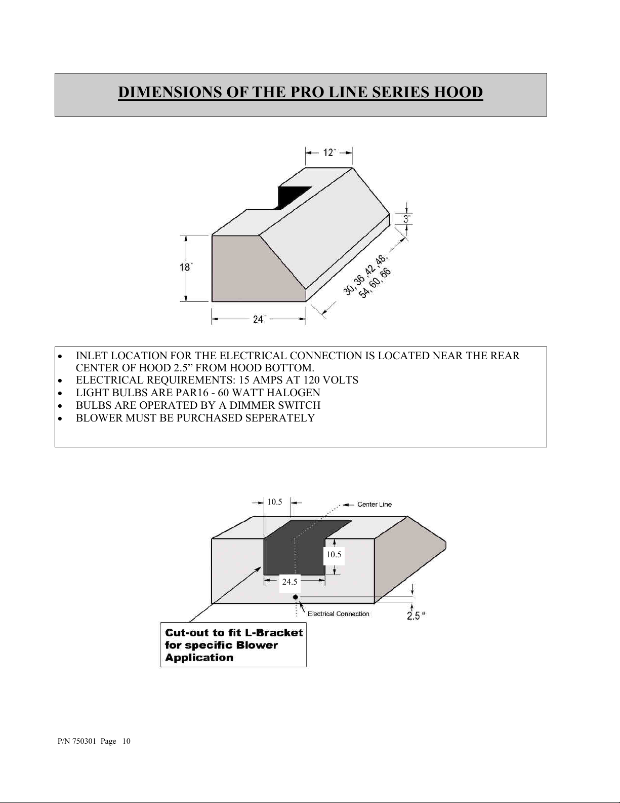
DIMENSIONS OF THE PRO LINE SERIES HOOD
INLET LOCATION FOR THE ELECTRICAL CONNECTION IS LOCATED NEAR THE REAR
CENTER OF HOOD 2.5” FROM HOOD BOTTOM.
ELECTRICAL REQUIREMENTS: 15 AMPS AT 120 VOLTS
LIGHT BULBS ARE PAR16 - 60 WATT HALOGEN
BULBS ARE OPERATED BY A DIMMER SWITCH
BLOWER MUST BE PURCHASED SEPERATELY
P/N 750301 Page 10
10.5
10.5
24.5
Page 11
SITE PREPARATION FOR PRO LINE SERIES
IN SELECTING THE PROPER HEIGHT TO MOUNT THE HOOD, TAKE INTO CONSIDERATION
THE STATURE OF THE PERSON OR PERSONS WHO WILL BE COOKING. A HEIGHT OF 30",
MINIMUM HEIGHT OFF OF COOKING SURFACE, TO 36" MAXIMUM HEIGHT OFF OF THE
COOKING SURFACE, WILL SUIT MOST USERS. IF MOUNTED AT A HEIGHT GREATER THAN
36" ABOVE THE COOKING SURFACE, THE HOOD SHOULD BE AT LEAST 6" WIDER THAN
THE COOKING APPLIANCE TO PROVIDE A PROPER CAPTURE OF HEAT AND GREASE.
(REFER TO THE RANGE MANUFACTURER'S GUIDELINES). ONCE THE PROPER HEIGHT IS
ESTABLISHED, DRAW A LEVEL LINE WHERE THE BOTTOM OF THE HOOD WILL REST. IF
PRACTICAL, MOUNT A BOARD EQUAL TO THE WIDTH OF THE HOOD ALONG THE LINE SO
YOU MAY REST THE HOOD ON IT WHILE INSTALLING. MARK A CENTER LINE ON THE
WALL EQUAL TO THE ENTIRE HEIGHT OF THE HOOD TO ASSIST WITH THE PROPER DUCT
ALIGNMENT AND HOOD PLACEMENT. DETERMINE STUD LOCATION AND MARK IT
CLEARLY. BECAUSE OF THE WEIGHT OF THE HOOD MAKE SURE THAT THE MOUNTING
SCREWS ARE DRIVEN INTO THE FRAMING AND NOT JUST THE DRYWALL. IT MAY BE
NECESSARY TO DRILL ADDITIONAL HOLES INTO THE CANOPY FOR PROPER ALIGNMENT.
IF ONLY ONE STUD CAN BE LOCATED, TOGGLE BOLTS OR ADDITIONAL FASTENING MUST
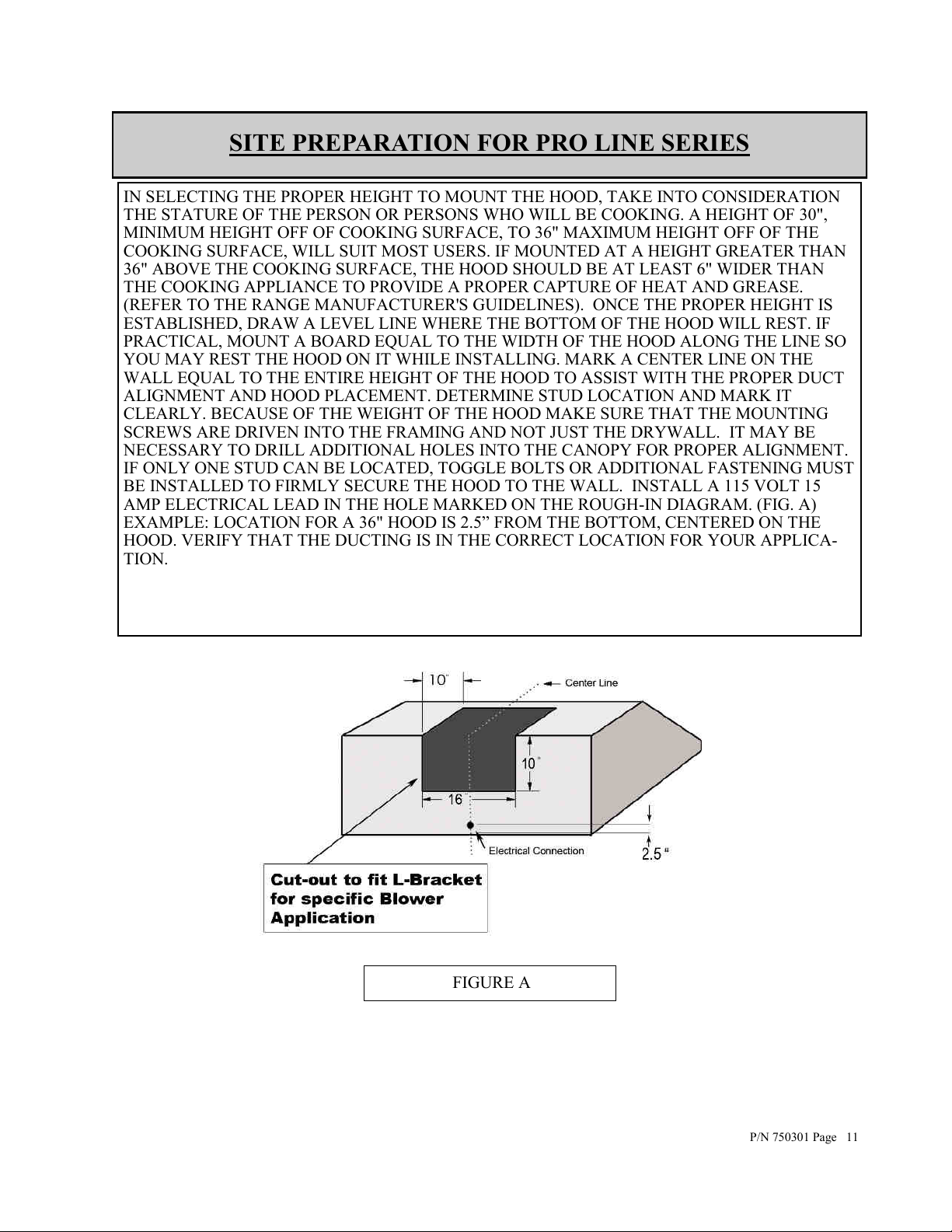
BE INSTALLED TO FIRMLY SECURE THE HOOD TO THE WALL. INSTALL A 115 VOLT 15
AMP ELECTRICAL LEAD IN THE HOLE MARKED ON THE ROUGH-IN DIAGRAM. (FIG. A)
EXAMPLE: LOCATION FOR A 36" HOOD IS 2.5” FROM THE BOTTOM, CENTERED ON THE
HOOD. VERIFY THAT THE DUCTING IS IN THE CORRECT LOCATION FOR YOUR APPLICA-
TION.
FIGURE A
P/N 750301 Page 11
Page 12
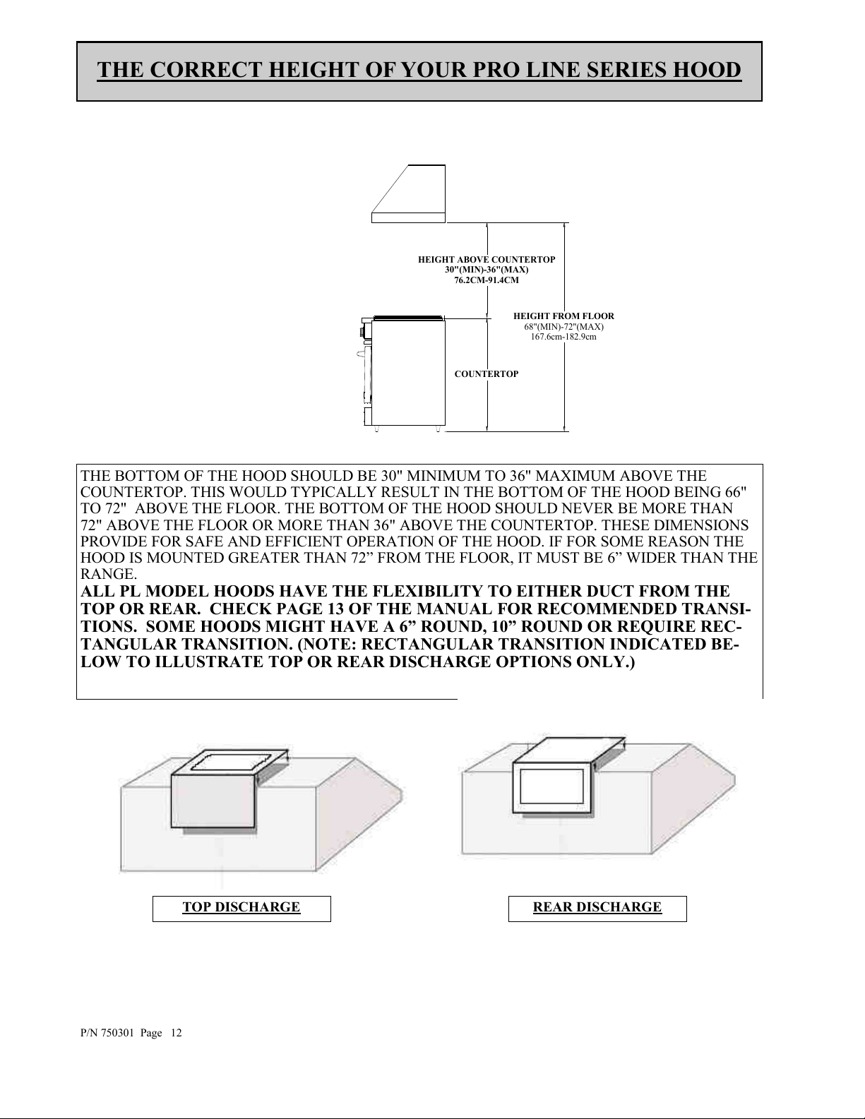
HEIGHT FROM FLOOR
68"(MIN)-72"(MAX)
167.6cm-182.9cm
COUNTERTOP
HEIGHT ABOVE COUNTERTOP
30"(MIN)-36"(MAX)
76.2CM-91.4CM
THE CORRECT HEIGHT OF YOUR PRO LINE SERIES HOOD
THE BOTTOM OF THE HOOD SHOULD BE 30" MINIMUM TO 36" MAXIMUM ABOVE THE
COUNTERTOP. THIS WOULD TYPICALLY RESULT IN THE BOTTOM OF THE HOOD BEING 66"
TO 72" ABOVE THE FLOOR. THE BOTTOM OF THE HOOD SHOULD NEVER BE MORE THAN
72" ABOVE THE FLOOR OR MORE THAN 36" ABOVE THE COUNTERTOP. THESE DIMENSIONS
PROVIDE FOR SAFE AND EFFICIENT OPERATION OF THE HOOD. IF FOR SOME REASON THE
HOOD IS MOUNTED GREATER THAN 72” FROM THE FLOOR, IT MUST BE 6” WIDER THAN THE
RANGE.
ALL PL MODEL HOODS HAVE THE FLEXIBILITY TO EITHER DUCT FROM THE
TOP OR REAR. CHECK PAGE 13 OF THE MANUAL FOR RECOMMENDED TRANSI-
TIONS. SOME HOODS MIGHT HAVE A 6” ROUND, 10” ROUND OR REQUIRE REC-
TANGULAR TRANSITION. (NOTE: RECTANGULAR TRANSITION INDICATED BE-
LOW TO ILLUSTRATE TOP OR REAR DISCHARGE OPTIONS ONLY.)
P/N 750301 Page 12
TOP DISCHARGE REAR DISCHARGE
Page 13
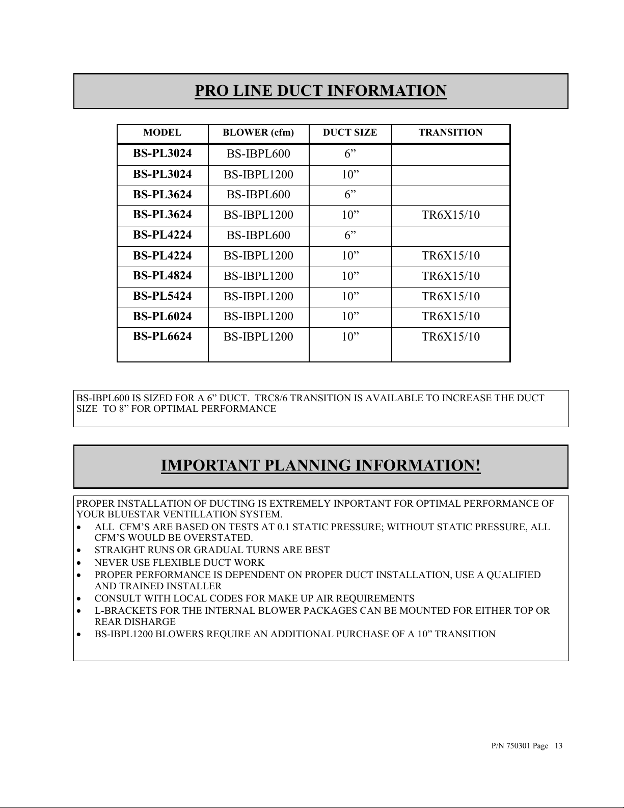
PRO LINE DUCT INFORMATION
MODEL BLOWER (cfm) DUCT SIZE TRANSITION
BS-PL3024
BS-PL3024
BS-PL3624
BS-PL3624
BS-PL4224
BS-PL4224
BS-PL4824
BS-PL5424
BS-PL6024
BS-PL6624
BS-IBPL600 6”
BS-IBPL1200 10”
BS-IBPL600 6”
BS-IBPL1200 10” TR6X15/10
BS-IBPL600 6”
BS-IBPL1200 10” TR6X15/10
BS-IBPL1200 10” TR6X15/10
BS-IBPL1200 10” TR6X15/10
BS-IBPL1200 10” TR6X15/10
BS-IBPL1200
10” TR6X15/10
BS-IBPL600 IS SIZED FOR A 6” DUCT. TRC8/6 TRANSITION IS AVAILABLE TO INCREASE THE DUCT
SIZE TO 8” FOR OPTIMAL PERFORMANCE
IMPORTANT PLANNING INFORMATION!
PROPER INSTALLATION OF DUCTING IS EXTREMELY INPORTANT FOR OPTIMAL PERFORMANCE OF
YOUR BLUESTAR VENTILLATION SYSTEM.
ALL CFM’S ARE BASED ON TESTS AT 0.1 STATIC PRESSURE; WITHOUT STATIC PRESSURE, ALL
CFM’S WOULD BE OVERSTATED.
STRAIGHT RUNS OR GRADUAL TURNS ARE BEST
NEVER USE FLEXIBLE DUCT WORK
PROPER PERFORMANCE IS DEPENDENT ON PROPER DUCT INSTALLATION, USE A QUALIFIED
AND TRAINED INSTALLER
CONSULT WITH LOCAL CODES FOR MAKE UP AIR REQUIREMENTS
L-BRACKETS FOR THE INTERNAL BLOWER PACKAGES CAN BE MOUNTED FOR EITHER TOP OR
REAR DISHARGE
BS-IBPL1200 BLOWERS REQUIRE AN ADDITIONAL PURCHASE OF A 10” TRANSITION
P/N 750301 Page 13
Page 14

INSTALLATION OF YOUR PRO LINE SERIES HOOD BLOWER
INSTALLATION OF BS-IBPL600 INTERNAL BLOWER KIT
REFER TO WIRING DIAGRAM
1. REMOVE SHIPPING BRACKET (SEE ITEM 1)FROM HOOD. DO NOT DISCARD SCREWS!
2. INSTALL BLOWER BRACKET WITH THE SCREWS REMOVED FROM THE SHIPPING
BRACKET.
3. LOCATE THE TERMINAL BLOCK INSIDE THE ELECTRICAL SUPPLY BOX.
4. CONNECT FAN # 1 WIRE TO TERMINAL BLOCK #4.
5. CONNECT FAN # 1 WIRE TO TERMINAL BLOCK #6.
6. CONNECT THE 115 VOLT SUPPLY WIRE TO TERMINAL BLOCK #2.
7. CONNECT THE 115 VOLT SUPPLY WIRE TO TERMINAL BLOCK #1.
INSTALLATION OF BS-IBPL1200 INTERNAL BLOWER KIT
REFER TO WIRING DIAGRAM
1. REMOVE SHIPPING BRACKET FROM HOOD. DO NOT DISCARD SCREWS!
FOR FAN #1
1. INSTALL BLOWER BRACKET WITH THE SCREWS REMOVED FROM THE SHIPPING
BRACKET.
2. LOCATE THE TERMINAL BLOCK INSIDE THE ELECTRICAL SUPPLY BOX.
3. CONNECT FAN # 1 WIRE TO TERMINAL BLOCK #4.
4. CONNECT FAN # 1 WIRE TO TERMINAL BLOCK #6.
5. CONNECT THE 115 VOLT SUPPLY WIRE TO TERMINAL BLOCK #2.
6. CONNECT THE 115 VOLT SUPPLY WIRE TO TERMINAL BLOCK #1.
FOR FAN #2
CONNECT FAN #2 WIRE TO TERMINAL BLOCK #3.
1. CONNECT FAN #2 WIRE TO TERMINAL BLOCK #5.
Item 1: shipping bracket should be used with remote blower, as the attachment for the flue. Once
removed attach blower as described above.
P/N 750301 Page 14
Shipping bracket
Blower motor bracket
Page 15
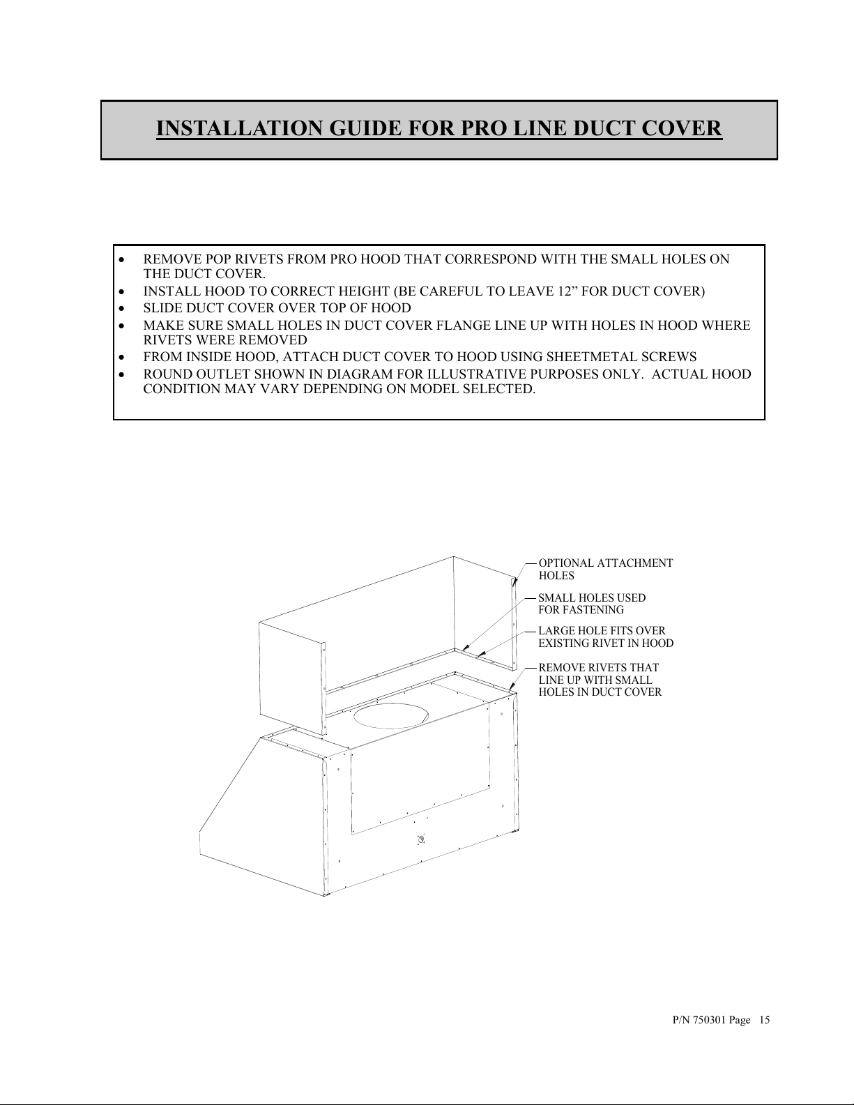
LARGE HOLE FITS OVER
EXISTING RIVET IN HOOD
REMOVE RIVETS THAT
LINE UP WITH SMALL
HOLES IN DUCT COVER
SMALL HOLES USED
FOR FASTENING
OPTIONAL ATTACHMENT
HOLES
INSTALLATION GUIDE FOR PRO LINE DUCT COVER
REMOVE POP RIVETS FROM PRO HOOD THAT CORRESPOND WITH THE SMALL HOLES ON
THE DUCT COVER.
INSTALL HOOD TO CORRECT HEIGHT (BE CAREFUL TO LEAVE 12” FOR DUCT COVER)
SLIDE DUCT COVER OVER TOP OF HOOD
MAKE SURE SMALL HOLES IN DUCT COVER FLANGE LINE UP WITH HOLES IN HOOD WHERE
RIVETS WERE REMOVED
FROM INSIDE HOOD, ATTACH DUCT COVER TO HOOD USING SHEETMETAL SCREWS
ROUND OUTLET SHOWN IN DIAGRAM FOR ILLUSTRATIVE PURPOSES ONLY. ACTUAL HOOD
CONDITION MAY VARY DEPENDING ON MODEL SELECTED.
P/N 750301 Page 15
Page 16
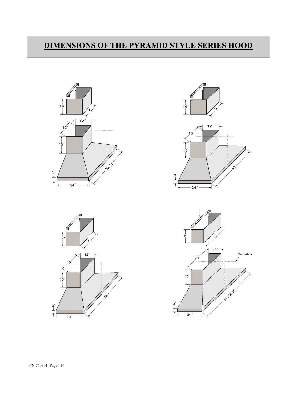
DIMENSIONS OF THE PYRAMID STYLE SERIES HOOD
P/N 750301 Page 16
Page 17
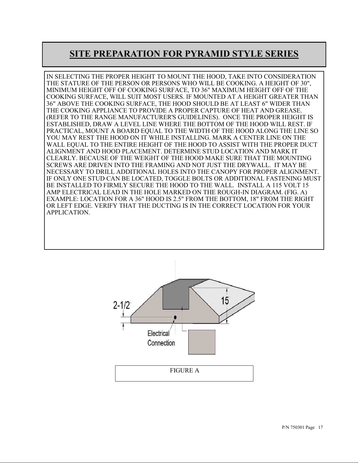
SITE PREPARATION FOR PYRAMID STYLE SERIES
IN SELECTING THE PROPER HEIGHT TO MOUNT THE HOOD, TAKE INTO CONSIDERATION
THE STATURE OF THE PERSON OR PERSONS WHO WILL BE COOKING. A HEIGHT OF 30",
MINIMUM HEIGHT OFF OF COOKING SURFACE, TO 36" MAXIMUM HEIGHT OFF OF THE
COOKING SURFACE, WILL SUIT MOST USERS. IF MOUNTED AT A HEIGHT GREATER THAN
36" ABOVE THE COOKING SURFACE, THE HOOD SHOULD BE AT LEAST 6" WIDER THAN
THE COOKING APPLIANCE TO PROVIDE A PROPER CAPTURE OF HEAT AND GREASE.
(REFER TO THE RANGE MANUFACTURER'S GUIDELINES). ONCE THE PROPER HEIGHT IS
ESTABLISHED, DRAW A LEVEL LINE WHERE THE BOTTOM OF THE HOOD WILL REST. IF
PRACTICAL, MOUNT A BOARD EQUAL TO THE WIDTH OF THE HOOD ALONG THE LINE SO
YOU MAY REST THE HOOD ON IT WHILE INSTALLING. MARK A CENTER LINE ON THE
WALL EQUAL TO THE ENTIRE HEIGHT OF THE HOOD TO ASSIST WITH THE PROPER DUCT
ALIGNMENT AND HOOD PLACEMENT. DETERMINE STUD LOCATION AND MARK IT
CLEARLY. BECAUSE OF THE WEIGHT OF THE HOOD MAKE SURE THAT THE MOUNTING
SCREWS ARE DRIVEN INTO THE FRAMING AND NOT JUST THE DRYWALL. IT MAY BE
NECESSARY TO DRILL ADDITIONAL HOLES INTO THE CANOPY FOR PROPER ALIGNMENT.
IF ONLY ONE STUD CAN BE LOCATED, TOGGLE BOLTS OR ADDITIONAL FASTENING MUST
BE INSTALLED TO FIRMLY SECURE THE HOOD TO THE WALL. INSTALL A 115 VOLT 15
AMP ELECTRICAL LEAD IN THE HOLE MARKED ON THE ROUGH-IN DIAGRAM. (FIG. A)
EXAMPLE: LOCATION FOR A 36" HOOD IS 2.5" FROM THE BOTTOM, 18" FROM THE RIGHT
OR LEFT EDGE. VERIFY THAT THE DUCTING IS IN THE CORRECT LOCATION FOR YOUR
APPLICATION.
FIGURE A
P/N 750301 Page 17
Page 18

HEIGHT FROM FLOOR
68"(MIN)-72"(MAX)
167.6cm-182.9cm
COUNTERTOP
HEIGHT ABOVE COUNTERTOP
30"(MIN)-36"(MAX)
76.2CM-91.4CM
THE CORRECT HEIGHT OF YOUR PYRAMID STYLE HOOD
THE BOTTOM OF THE HOOD SHOULD BE 30" MINIMUM TO 36" MAXIMUM ABOVE THE
COUNTERTOP. THIS WOULD TYPICALLY RESULT IN THE BOTTOM OF THE HOOD BEING 66"
TO 72" ABOVE THE FLOOR. THE BOTTOM OF THE HOOD SHOULD NEVER BE MORE THAN
72" ABOVE THE FLOOR OR MORE THAN 36" ABOVE THE COUNTERTOP. THESE DIMENSIONS
PROVIDE FOR SAFE AND EFFICIENT OPERATION OF THE HOOD. IF FOR SOME REASON THE
HOOD IS MOUNTED GREATER THAN 72” FROM THE FLOOR, IT MUST BE 6” WIDER THAN THE
RANGE.
ALL PC MODELS TOP DUCT ONLY. (NOTE: THE PC HOOD CAN BE DUCTED TO
THE REAR WITH THE USE OF A 90 DGREE ELBOW (NOT INCLUDED). CHECK
PAGE 19 OF MANUAL FOR RECOMMENDED TRANSITIONS. (ROUND DUCTING
SHOWN FOR ILLUSTRATIVE PURPOSES. ACTUAL HOOD MAY VARY)
BS-PC3024 CANNOT ACCEPT THE BS-PCIB1200 INTERNAL BLOWER
REAR DISCHARGE TOP DISCHARGE
P/N 750301 Page 18
Page 19
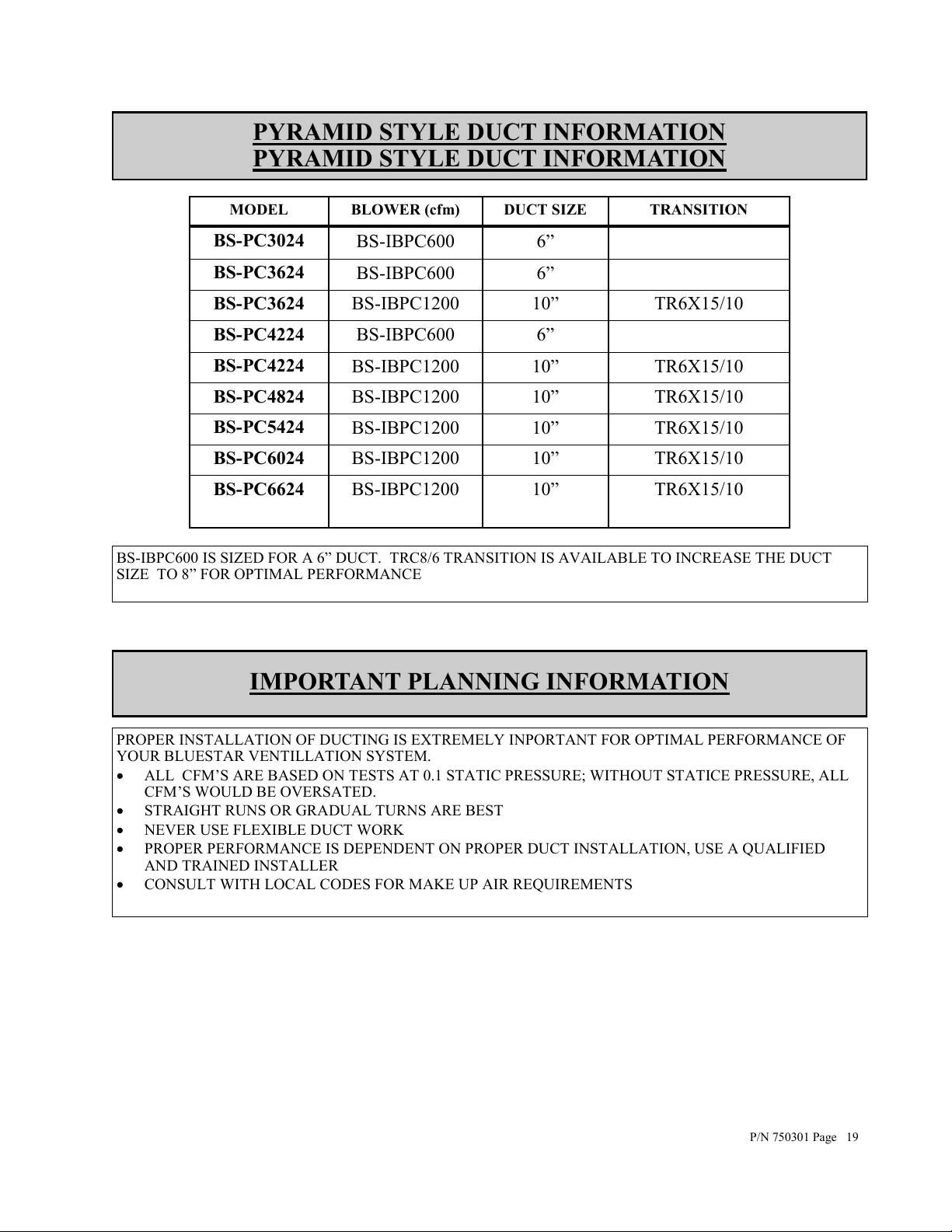
PYRAMID STYLE DUCT INFORMATION
PYRAMID STYLE DUCT INFORMATION
MODEL BLOWER (cfm) DUCT SIZE TRANSITION
BS-PC3024
BS-PC3624
BS-PC3624
BS-PC4224
BS-PC4224
BS-PC4824
BS-PC5424
BS-PC6024
BS-PC6624
BS-IBPC600 6”
BS-IBPC600 6”
BS-IBPC1200 10” TR6X15/10
BS-IBPC600 6”
BS-IBPC1200 10” TR6X15/10
BS-IBPC1200 10” TR6X15/10
BS-IBPC1200 10” TR6X15/10
BS-IBPC1200 10” TR6X15/10
BS-IBPC1200
10” TR6X15/10
BS-IBPC600 IS SIZED FOR A 6” DUCT. TRC8/6 TRANSITION IS AVAILABLE TO INCREASE THE DUCT
SIZE TO 8” FOR OPTIMAL PERFORMANCE
IMPORTANT PLANNING INFORMATION
PROPER INSTALLATION OF DUCTING IS EXTREMELY INPORTANT FOR OPTIMAL PERFORMANCE OF
YOUR BLUESTAR VENTILLATION SYSTEM.
ALL CFM’S ARE BASED ON TESTS AT 0.1 STATIC PRESSURE; WITHOUT STATICE PRESSURE, ALL
CFM’S WOULD BE OVERSATED.
STRAIGHT RUNS OR GRADUAL TURNS ARE BEST
NEVER USE FLEXIBLE DUCT WORK
PROPER PERFORMANCE IS DEPENDENT ON PROPER DUCT INSTALLATION, USE A QUALIFIED
AND TRAINED INSTALLER
CONSULT WITH LOCAL CODES FOR MAKE UP AIR REQUIREMENTS
P/N 750301 Page 19
Page 20
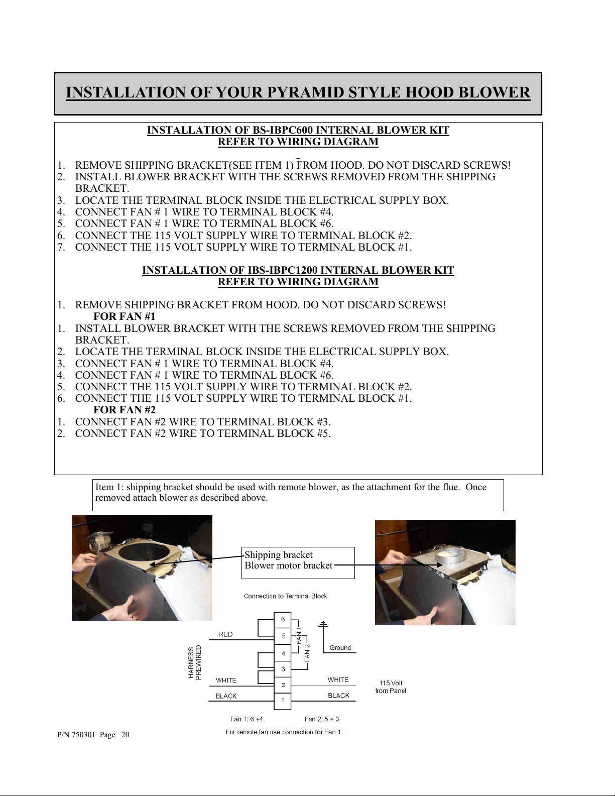
INSTALLATION OF YOUR PYRAMID STYLE HOOD BLOWER
INSTALLATION OF BS-IBPC600 INTERNAL BLOWER KIT
REFER TO WIRING DIAGRAM
1. REMOVE SHIPPING BRACKET(SEE ITEM 1) FROM HOOD. DO NOT DISCARD SCREWS!
2. INSTALL BLOWER BRACKET WITH THE SCREWS REMOVED FROM THE SHIPPING
BRACKET.
3. LOCATE THE TERMINAL BLOCK INSIDE THE ELECTRICAL SUPPLY BOX.
4. CONNECT FAN # 1 WIRE TO TERMINAL BLOCK #4.
5. CONNECT FAN # 1 WIRE TO TERMINAL BLOCK #6.
6. CONNECT THE 115 VOLT SUPPLY WIRE TO TERMINAL BLOCK #2.
7. CONNECT THE 115 VOLT SUPPLY WIRE TO TERMINAL BLOCK #1.
INSTALLATION OF IBS-IBPC1200 INTERNAL BLOWER KIT
REFER TO WIRING DIAGRAM
1. REMOVE SHIPPING BRACKET FROM HOOD. DO NOT DISCARD SCREWS!
FOR FAN #1
1. INSTALL BLOWER BRACKET WITH THE SCREWS REMOVED FROM THE SHIPPING
BRACKET.
2. LOCATE THE TERMINAL BLOCK INSIDE THE ELECTRICAL SUPPLY BOX.
3. CONNECT FAN # 1 WIRE TO TERMINAL BLOCK #4.
4. CONNECT FAN # 1 WIRE TO TERMINAL BLOCK #6.
5. CONNECT THE 115 VOLT SUPPLY WIRE TO TERMINAL BLOCK #2.
6. CONNECT THE 115 VOLT SUPPLY WIRE TO TERMINAL BLOCK #1.
FOR FAN #2
1. CONNECT FAN #2 WIRE TO TERMINAL BLOCK #3.
2. CONNECT FAN #2 WIRE TO TERMINAL BLOCK #5.
Item 1: shipping bracket should be used with remote blower, as the attachment for the flue. Once
removed attach blower as described above.
P/N 750301 Page 20
Shipping bracket
Blower motor bracket
Page 21

INSTALLATION GUIDE FOR FLUE (PYRAMID STYLE HOOD)
1. MEASURE FROM TOP OF THE CANOPY TO CEILING AND SUBTRACT 1/8" FOR CLEAR-
ANCE.
2. PLACE THE DUCT COVER TOP INSIDE THE DUCT COVER BASE AND LOWER UNTIL DE-
SIRED HEIGHT IS FOUND. (TO ELIMINATE SCRATCHES, MAKE A MARK ON THE DUCT
COVER TOP FOR THE DESIRED LOWERING POINT BY SUBTRACTING 15" FROM THE TO-
TAL HEIGHT NEEDED.)
3. USE THE RETAINING SCREWS TO FASTEN IN PLACE.
4. SLIDE THE DUCT COVER IN PLACE AND FASTEN FROM INSIDE CANOPY USING SHEET
METAL SCREWS.
NOTE: FOR INSTALLATIONS WITH CEILINGS ABOVE 9', USE OPTIONAL CUSTOM FLUES. SEE
PRODUCT LITERATURE FOR DETAILS.
MODEL “A” DIM “B” MAXIMUM “C” DIM
BS-PC3024 15” 27” 12”
BS-PC3624 15” 27” 12”
BS-PC4224 15” 27” 15”
BS-PC4824 15” 27” 18”
BS-PC5424 15” 27” 24”
BS-PC6024 15” 27” 24”
BS-PC6024 15” 27” 24”
P/N 750301 Page 21
Page 22
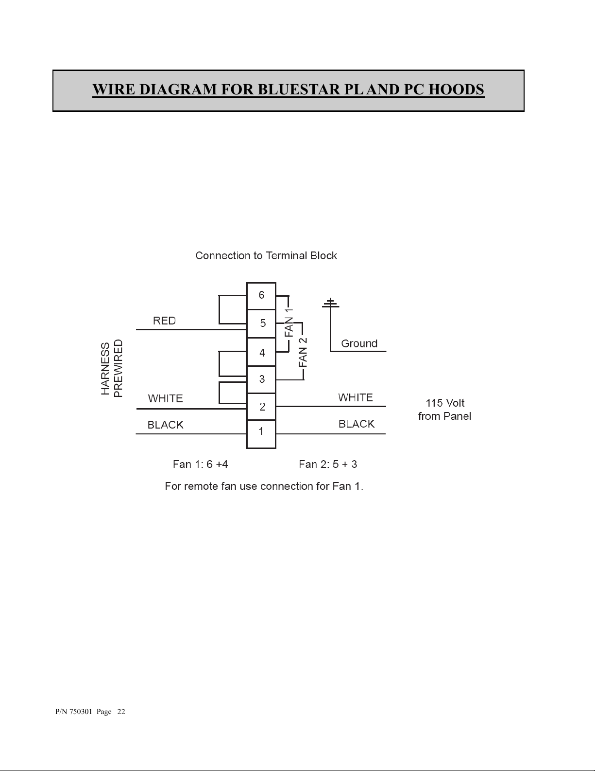
WIRE DIAGRAM FOR BLUESTAR PL AND PC HOODS
P/N 750301 Page 22
Page 23

CLEANING AND MAINTENANCE
YOUR HOOD MUST BE KEPT CLEAN AND MAINTAINED PROPERLY!!
BAFFLE FILTERS
BAFFLE FILTERS SHOULD BE EXAMINED PERIODICALLY TO ASSURE THAT ALL SUR-
FACES AND PARTS ARE CLEAN
THE FILTERS ARE DISHWASHER SAFE OR IN A SINK WITH HOT, SOAPY WATER
EASY PERIODIC CLEANING WILL ASSURE OPTIMUM FILTER PERFORMANCE
DO NOT USE CAUSTIC DETERGENT TO CLEAN THE FILTERS. ABRASIVE CLEANERS MAY
HARM OR DAMAGE THE FINISH
DO NOT DISASSEMBLE THE BAFFLE FILTER. DISASSEMBLY WILL VOID THE WARRAN-
TY.
CANOPY
DO NOT USE ABRASIVE CLEANERS, STEEL WOOL PADS, ABRASIVE CLOTHS OR CLEAN-
ERS WITH CHLORIDES
DO NOT ALLOW GREASE TO ACCUMULATE, FOR BEST RESULTS WIPE THE CANOPY
DOWN WITH A SOFT CLOTH AND HOT, SOAPY WATER
THE CLEANING OF THE OUTSIDE OF THE HOOD DEPENDS ON THE MATERIAL USED AS A
DECORATIVE EXTERIOR. FOR STAINLESS STEEL AND POWDER COATED METALS, CLEAN
WITH SOAP AND WATER ONLY. DO NOT USE ABRASIVE OR AGGRESSIVE CHEMICALS!
REPLACING THE LIGHT BULBS
UNSCREW HALOGEN LIGHT BULB
REPLACE HALOGEN WITH 60 WATT, 115 VOLT HALOGEN, PAR 16 LIGHT BULB
P/N 750301 Page 23
Page 24

LIMITED WARRANTY
BlueStar® Cooking Appliances, BlueStar® Ventilation Hoods, Prizer Hoods® Ventilation Hoods and
Abbaka Ventilation hoods and remote blowers
Before using your Product, please read this Limited Warranty and Arbitration Clause carefully to
understand your rights.
This Warranty is provided to you by Prizer-Painter Stove Works, Inc. (“Prizer-Painter”), which warrants
the parts of your BlueStar® cooking appliance, BlueStar® ventilation hood, Prizer Hoods® ventilation hood,
or Abbaka ventilation hood or remote blower (“Product”), as described below.
This Warranty covers the owner of the residence in which the Product is installed, and his or her spouse
(“Owner” or “You”).
Products Covered
This Warranty applies only to BlueStar® cooking appliances, BlueStar® ventilation hoods, Prizer Hoods
ventilation hoods and Abbaka ventilation hoods and remote blowers purchased in the continental U.S. and
Canada on or after April 1, 2019. This Warranty applies only to Product sold by a BlueStar® authorized
dealer or Prizer-Painter directly for use in residential properties only. Products must be installed by a
qualified, licensed installer. Any service call deemed to be the result of improper installation shall be the
responsibility of the owner. This Warranty is also void if the original factory installed serial number is
altered or removed from the Product.
Products Not Covered
This Warranty does not apply to Products installed or used in any commercial or other non-residential
property such as, but not limited to, day care facilities, hotels, motels, firehouses and nursing homes. This
Warranty does not cover Products installed outside the U.S. or Canada. This Warranty does not apply to
gas type conversions on cooking appliances not completed by a certified gas technician, licensed plumber
or certified BlueStar® servicers.
Full Two-Year Warranty
Product Registration is not required to obtain Warranty Coverage but is highly recommended for optimal
servicing and affects the length and certain remedies available under the warranty.
If the Product is properly registered within 90 days of Installation Date: For two (2) years from the date
that the Product is originally installed, this Warranty covers all parts and labor to repair or replace, at our
discretion, any functional component of the Product, that is defective in materials or workmanship.
Replacement service will only be provided if and when attempts to repair the Product have been
exhausted. Such repair or replacement service must be performed by a factory authorized service agent
located within 100 miles roundtrip from the location of the Product. Service will be provided during
normal business hours. The Owner will be responsible for any and all costs associated with additional
mileage, non-standard service or overtime, and special equipment required to remove the Product so that
service may be performed. Prizer-Painter reserves the right to deny warranty coverage for excessive
installation delays.
For products not properly registered: For one (1) year from the date that the Product is originally installed,
this Warranty covers all parts and labor to repair or replace, at our discretion, any functional component
of the Product, that is defective in materials or workmanship. Replacement service will only be provided
if and when attempts to repair the Product have been exhausted. Such repair or replacement service must
be performed by a factory authorized service agent located within 100 miles roundtrip from the location
For further information about this warranty,
contact Prizer-Painter Customer Service at 1-800-449-8691
®
Page 25

of the Product. Service will be provided during normal business hours. The Owner will be responsible
for any and all costs associated with additional mileage, non-standard service or overtime, and special
equipment required to remove the Product so that service may be performed. Prizer-Painter reserves the
right to deny warranty coverage for excessive installation delays.
Limited Cosmetic Component Warranty: This Warranty covers the repair or replacement of all
cosmetic component flaws for thirty (30) calendar days from the date of delivery of the Product to the
owner’s home from a BlueStar® authorized dealer. Cosmetic components include top grates, ring grates,
plate rail, kick panel, body sides, glass, control panel, door panel, back guards, oven seals), front sides of
hoods, and hoods strapping. Cosmetic components flaws include visible chips, scratches, dents, provided,
however, that cosmetic flaws caused by freight damage are excluded.
Limited Warranty on Floor Models Not Used For Demonstration: Floor Models are covered by a one
(1) year limited functional parts and related services warranty, with proof of date of installation. There is
no cosmetic warranty of any kind for floor models.
Limited Warranty on Floor Models Used For Demonstration: Floor Models used for demonstration
are covered by a ninety (90) day limited parts warranty only, with proof of date of installation. There is
no service or cosmetic warranty of any kind for floor models.
Limited Warranty on Product Refurbished
Refurbished Products are covered by a six (6) months limited functional parts and labor warranty, with
proof of installation, as well as an additional six (6) months limited parts warranty. There is no cosmetic
warranty of any kind on Refurbished Product.
Registration
Registration is strongly recommended. While not necessary to effectuate warranty coverage, it is the best
way for Prizer-Painter to communicate with you about important events and also provides additional
warranty coverage. TO REGISTER, please fill out the “Performance Checklist and Warranty Form”
located online at www.bluestarcooking.com/support/product-registration. Or mail the form located in the
back of the Product Use and Care Manual to: Warranty Department, Prizer-Painter Stove Works, 318
June Avenue, Blandon, PA 19510-9566.
Obtaining Warranty Service
If a Warranty claim is not submitted as required, such claim will be invalid and will not be honored.
To obtain Warranty service, where applicable, the Owner must call the Service Center (toll free: 1-800-
449-8691) or fill out the online form at www.bluestarcooking.com/service to report a warranty claim, and
may be required to, at the time, provide (1) the model number of the Product, (2) the serial number of the
Product, (3) proof of delivery, (4) a signed installation receipt, (5) a description of the claimed defect, and
(6) proof of purchase of the Product, including the original retail receipt or invoice to establish the
Warranty Period. Prizer-Painter must be given an opportunity to inspect any Product subject to a
warranty claim. All warranty related service repairs must be performed by a factory authorized service
agent.
For further information about this warranty,
contact Prizer-Painter Customer Service at 1-800-449-8691
Page 26

This Limited Warranty gives you specific legal rights, and you may also have other rights that may vary
from state to state or province to province.
Out of Warranty Product
Prizer-Painter is under no obligation, at law otherwise, to provide you with any concessions, including
repairs, pro-rates or Product replacement, once this warranty has expired.
What Is Not Covered
This Warranty does not cover, and specifically excludes:
Damages caused by shipping.
Damage or repairs to the porcelain igniters, calibrations and normal adjustments after installation
and setup, including burner adjustments.
Normal wear and tear, care, and maintenance of the Product as described in the installation and
operating manual, such as cleaning of parts, discoloration of the griddle, rust, gasket materials,
ceramic materials, and fuses.
Damage or repairs caused by alterations or modifications, abuse, excessive force, misuse, neglect,
or improper installation, instruction, handling, operation, maintenance or storage.
Accidental or intentional damage.
Damage or repairs caused by unauthorized or improper service or repairs.
Damages or repairs as a result of natural disasters, fires, floods, earthquakes, winds, lightning,
corrosive atmosphere, loss of electrical power to the Product for any reason, or other conditions
beyond Prizer-Painter’s control.
Damage or repairs caused by alteration for outdoor use.
Damage or repairs caused by the use of harsh chemicals or cleaning products improperly applied.
Discolorations to backguards from use of griddle or burners.
The replacement of a part or Product under this Warranty does not extend the Warranty period.
If the Product is removed from the property where it was originally installed .
Slight color variations may be noticed because of differences in painted parts, kitchen lighting,
product placement, and other factors; this warranty does not apply to color variations.
Service calls to educate the customer on proper use and care of the product.
Failure of the product when used for commercial, business, rental or any application other than for
residential consumer use.
Liability or responsibility for damage to surrounding property including cabinetry, floors, ceilings
and other structures or objects around the Product.
Consequential or incidental damage, including but not limited to food or medicine loss, time away
from work or restaurant meals.
This warranty is in lieu of all other express warranties. No employee or representative of Prizer-Painter is
authorized to make any modification, extension or addition to this Limited Warranty.
ALL IMPLIED WARRANTIES, INCLUDING BUT NOT LIMITED TO WARRANTIES OF
MERCHANTABILITY AND FITNESS FOR PARTICULAR PURPOSE ARE LIMITED TO THE
For further information about this warranty,
contact Prizer-Painter Customer Service at 1-800-449-8691
Page 27

DURATION OF THIS WARRANTY. Some states and provinces do not allow limitations on implied
warranties, so the above limitation may not apply to you.
THE OWNER AND PRIZER-PAINTER AGREE THAT THE REMEDIES SET OUT HEREIN
ARE THE OWNER’S EXCLUSIVE REMEDIES FOR BREACH OF ALL WARRANTIES,
EXPRESS OR IMPLIED.
WHETHER ANY CLAIM IS BASED ON NEGLIGENCE OR OTHER TORT, BREACH OF
WARRANTY OR BREACH OF CONTRACT, OR ANY THEORY, PRIZER-PAINTER SHALL
IN NO EVENT BE LIABLE FOR INCIDENTAL, CONSEQUENTIAL OR SPECIAL DAMAGES,
INCLUDING BUT NOT LIMITED TO DAMAGES FOR EXPENSES, SUCH AS, EXTRA
UTILITY EXPENSES, SHIPPING COSTS RELATED TO REPAIR OR REPLACEMENT OF
ANY PRODUCT OR DAMAGES TO PROPERTY, RESULTING FROM BREACH OF THIS
WARRANTY OR ANY IMPLIED WARRANTY. Some states and provinces do not allow the
exclusion or limitation of incidental or consequential damages, so these provisions may not apply to you.
Where Can Any Legal Remedies Be Pursued
Please see the Arbitration Clause and Related Provisions, which affect your legal rights. Read this
Arbitration Clause and its related provisions carefully. The Arbitration Clause is also available on Prizer-
Painter’s website.
For further information about this warranty,
contact Prizer-Painter Customer Service at 1-800-449-8691
Page 28
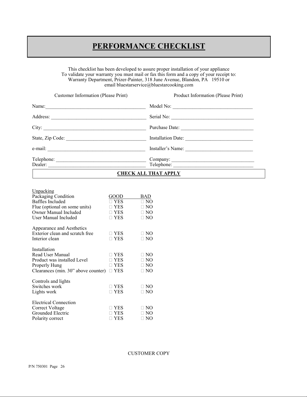
PERFORMANCE CHECKLIST
This checklist has been developed to assure proper installation of your appliance
To validate your warranty you must mail or fax this form and a copy of your receipt to:
Warranty Department, Prizer-Painter, 318 June Avenue, Blandon, PA 19510 or
email bluestarservice@bluestarcooking.com
Customer Information (Please Print) Product Information (Please Print)
Name:________________________________________ Model No: ________________________________
Address: ______________________________________ Serial No: _________________________________
City: _________________________________________ Purchase Date: _____________________________
State, Zip Code: ________________________________ Installation Date: ___________________________
e-mail: _______________________________________ Installer’s Name: ___________________________
Telephone: ____________________________________ Company: _________________________________
Dealer: _______________________________________ Telephone: ________________________________
CHECK ALL THAT APPLY
Unpacking
Packaging Condition GOOD BAD
Baffles Included YES NO
Flue (optional on some units) YES NO
Owner Manual Included YES NO
User Manual Included YES NO
Appearance and Aesthetics
Exterior clean and scratch free YES NO
Interior clean YES NO
Installation
Read User Manual YES NO
Product was installed Level YES NO
Properly Hung YES NO
Clearances (min. 30” above counter) YES NO
Controls and lights
Switches work YES NO
Lights work YES NO
Electrical Connection
Correct Voltage YES NO
Grounded Electric YES NO
Polarity correct YES NO
P/N 750301 Page 26
CUSTOMER COPY
Page 29
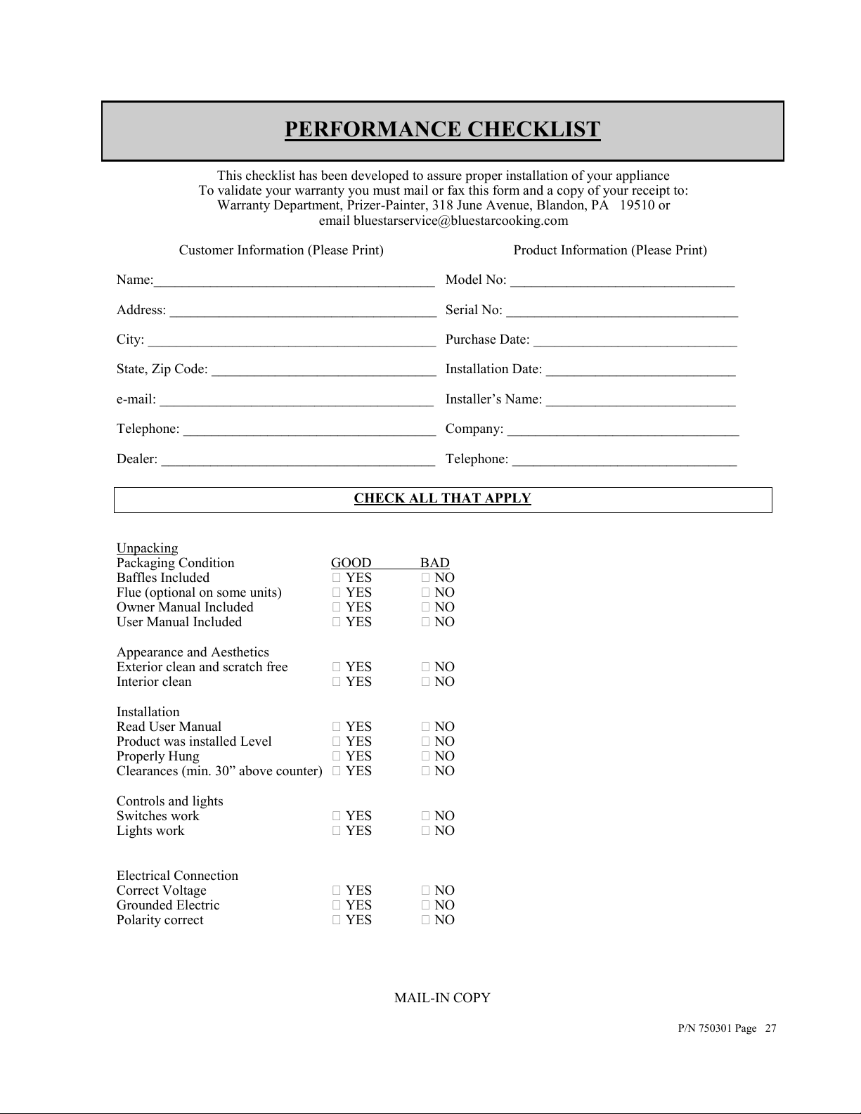
PERFORMANCE CHECKLIST
This checklist has been developed to assure proper installation of your appliance
To validate your warranty you must mail or fax this form and a copy of your receipt to:
Warranty Department, Prizer-Painter, 318 June Avenue, Blandon, PA 19510 or
email bluestarservice@bluestarcooking.com
Customer Information (Please Print) Product Information (Please Print)
Name:________________________________________ Model No: ________________________________
Address: ______________________________________ Serial No: _________________________________
City: _________________________________________ Purchase Date: _____________________________
State, Zip Code: ________________________________ Installation Date: ___________________________
e-mail: _______________________________________ Installer’s Name: ___________________________
Telephone: ____________________________________ Company: _________________________________
Dealer: _______________________________________ Telephone: ________________________________
CHECK ALL THAT APPLY
Unpacking
Packaging Condition GOOD BAD
Baffles Included YES NO
Flue (optional on some units) YES NO
Owner Manual Included YES NO
User Manual Included YES NO
Appearance and Aesthetics
Exterior clean and scratch free YES NO
Interior clean YES NO
Installation
Read User Manual YES NO
Product was installed Level YES NO
Properly Hung YES NO
Clearances (min. 30” above counter) YES NO
Controls and lights
Switches work YES NO
Lights work YES NO
Electrical Connection
Correct Voltage YES NO
Grounded Electric YES NO
Polarity correct YES NO
MAIL-IN COPY
P/N 750301 Page 27
 Loading...