

Page 1

Installation Instructions
Remote Fans
CFMR1000 & CFMR1400
Inline Blowers
INLB300, INLB600 & INLB1200
Page 2

PLEASE READ COMPLETE INSTRUCTIONS BEFORE PROCEEDING.
INSTALLATION MUST COMPLY WITH ALL LOCAL CODES.
IMPORTANT: Save these instructions for the local electrical inspector’s use.
INSTALLER: Please leave these instructions with this unit for the owner.
OWNER: Please retain the instructions for future reference.
SAFETY WARNING: Turn power circuit OFF at the service panel and lock panel door before
wiring this unit.
IMPORTANT SAFETY INSTRUCTIONS
CAUTION – To reduce the
risk of fire, electric shock, or
injury to people, observe the
following:
1. Use this rangehood only in
the manner intended by the
manufacturer. If you have
any questions, contact the
manufacturer – Prizer
Hoods.
2. Before servicing or cleaning
the unit, switch power off at
service panel and lock the
panel to prevent the power
from being switched on
accidentally. When switched
off for service, attach a tag to
the service panel to indicate
power has been switched off
for maintenance.
3. Install this rangehood only
with remote fan models rated
maximum 12.8A or in-hood
fans manufacturered by
Prizer Hoods, CFM300,
CFM600, CFM1200.
CAUTION: FOR GENERAL VENTILATION
USE ONLY. DO NOT USE TO EXHAUST
HAZARDOUS OR EXPLOSIVE MATERIALS
OR VAPOR.
CAUTION – To reduce the
risk of a rangetop grease fire.
1. Never leave cooktop surface
unattended while on high
setting
2. Boil overs cause smoke and
greasy spillovers may ignite.
Heat oils slowly on low or
medium settings.
3. Hood fan should always be
ON when cooking on high
heat or when flambeing
foods (i.e. Crepes Suzette,
Cherries Jubilee, Peppercorn
Beef Flambe.)
4. Clean in-hood fans
frequently. Do not allow
grease to accumulate on fan
or baffle filters.
5. Always use cookware
appropriate for the size of the
surface element.
CAUTION – To reduce the
risk of injury to people, in the
event of a rangetop grease fire,
observe the following:
1. SMOTHER FLAMES with a
tight fitting lid, cookie sheet
or other metal tray.
Immediately turn the gas
burner OFF. NEVER USE
WATER, wet dish-cloths or
towels as a violent steam
explosion will occur.
2. PREVENT BURNS. If gas
flames do not extinguish
immediately: EVACUATE
AND CALL THE FIRE
DEPARTMENT.
3. NEVER PICK UP A
FLAMING PAN as you may
sustain burns.
4. Use fire extinguisher only if:
• You know you have a class
ABC extinguisher, and you
know how to operate it.
• Fire is small & contained in
the area where it started.
• Fire department is being
called.
• You can fight the fire with
your back to an exit.
Page 3

SAFETY PROCEDURES FOR INSTALLING YOUR
NEW PRIZER HOOD (continued)
CAUTION – To reduce the risk of fire, electric shock, or injury to people, observe the following:
CAUTION – For general ventilation use only. Do not use to exhaust hazardous or explosive materials
or vapors.
1. Installation work and electrical wiring must be done by a qualified installer in accordance with all
applicable codes and standards, including re-rated construction.
2. Sufficient air is needed for proper combustion and gas exhaustion through the flue to prevent
backdrafting. Follow the manufacturer’s guidelines and safety standards such as those published by the
National Fire Protection Association (NFPA), and the American Society of Heating, Refrigeration and
Air Conditioning Engineers (ASHRAE), and the local building code authorities.
3. When cutting/drilling into a wall or ceiling, avoid damage to electrical wiring and other hidden utilities.
4. In-hood or in-line fans must be vented to the outdoors.
5. If a ventilation unit is to be installed over a tub or shower, it must be marked as appropriate for the
application and be connected to a GFCI (Ground Fault Circuit Interrupter) – protected branch circuit.
6. NEVER place a control switch where it can be reached from a tub or shower.
7. CAUTION – To reduce the risk of fire within walls or roofs, use only metal ductwork.
8. Install this hood in accordance with all requirements specified by the manufacturer of your
cooktop/range.
9. Install this hood using required clearance from cooking surface to combustible material specified in
cooktop installation instructions.
READ & SAVE: UPON RECEIVING YOUR HOOD
• The high degree of craftsmanship in the construction
and finish of your hood requires careful handling to
ensure proper installation.
• Do not remove your hood from its carton until you are
ready to hang it.
• Do not store your hood anywhere other than within the
carton. If it is necessary to remove your hood from the
carton, place it on a blanket or padded area that will
protect your hood from scratches or indentations.
• Do not lift the hood by its utensil rail. Place your
fingers under the lower reveal of the hood. Grasp
firmly and lift.
• Wearing cotton gloves are preferred. They will protect
the surface from fine scratches and eliminate
fingerprints.
• Remove all rings, watches, belt buckles and jackets
(snaps/zippers) to prevent scratches on the hood.
• If applicable, do not remove the protective covering
from your hood until the installation process is
complete. It will be necessary to remove only a small
portion on the back side for a wall mounted hood in
order to position in place.
• Located within the hood cavity (behind the baffles) are
component parts and halogen bulbs.
Page 4
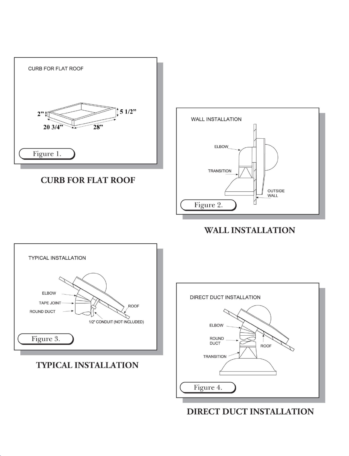
MOUNTING OPTIONS FOR REMOTE FANS
Page 5
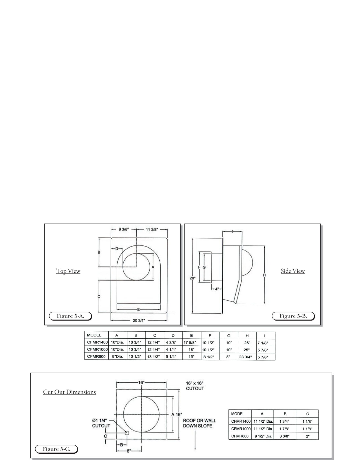
MOUNTING REMOTE FANS ON ROOF OR OUTSIDE WALL
To prepare for mounting a remote fan, inspect the blower wheel to ensure it turns freely. Do not replace the
top unit to the remote fan until the installation has been completed. A remote fan cannot be installed in a
condition where the exhaust/discharge opening is less than 15” from the ground level. NOTE: There may be
some local codes that will not permit this kind of installation. Heavy snow will prevent the damper from
opening due to snow blockage. The installer must check all local codes for outdoor wall installation of the
remote fan.
1. Cut out a round hole to accommodate the size ducting you will be using. Cut a second hole for the
electrical conduit. (see Figure 5-C)
2. When installing a remote fan on a flat roof or a roof with a pitch less than 1 ½” in 12 inches, install the
remote fan in such a way that the discharge (the lowest portion of the curb) is directed away from any
prevailing winds.
3. When installing a remote fan on a roof or outside wall, direct the discharge (the lowest portion of the
curb) pointing down the slope as this is in accordance with the Standard Roofing Procedures: front
discharge edge should be on the top of the shingles and the rear edge underneath the shingles.
• NOTE: The remote fan unit must be sealed between the roof (or outside wall) and the underside
of the flange with roofing mastic to prevent leaks.
4. Connect the remote fan (CFMR1000 & CFMR1400) to the exhaust system’s round duct. Use an
adjustable elbow to attach to the roof angle.
5. Using duct tape, seal all joints to prevent air leaks.
6. NOTE: Clearance to combustible materials is 0”.
Page 6
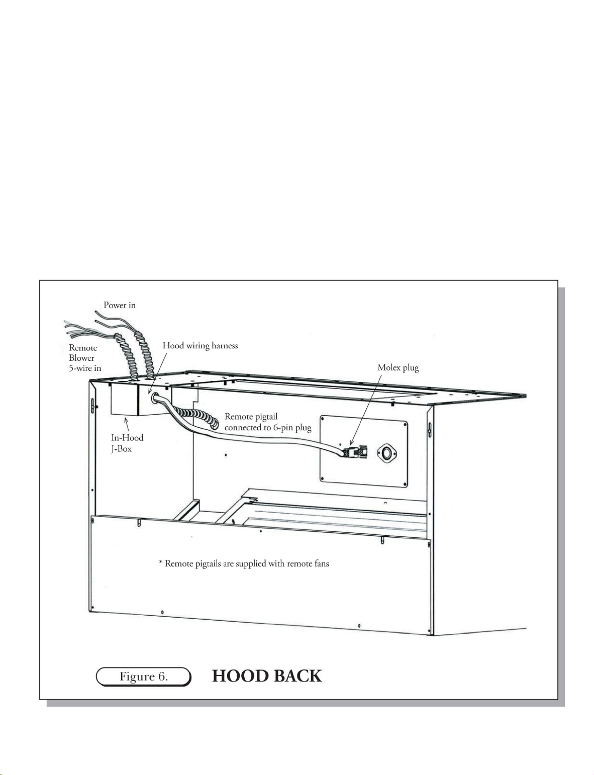
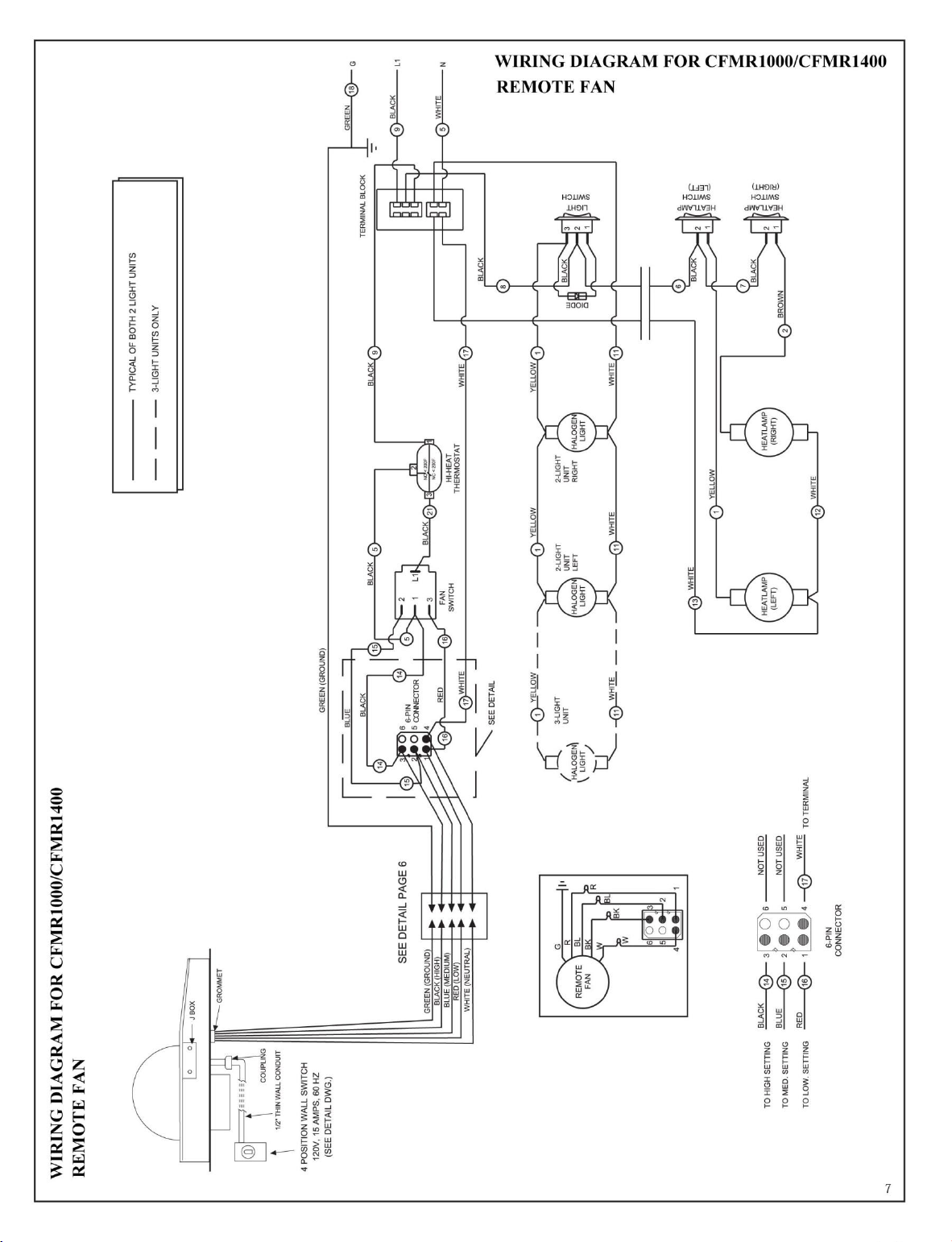
CONNECTING THE 3-SPEED FAN CONTROL TO THE REMOTE FAN
1. Power supply required for remote fans are 15 amps. @ 120V. AC, 60Hz. connected per local codes.
2. Run three #14 AWG wires (black, white and green) from the power supply at the electrical circuit panel
in the hood J-box (see Figure 6).
3. Run five wires from hood J-box through the walls to the remote fan, using color coded wires
corresponding to color codes in diagram (see Figure 7. Page 6)
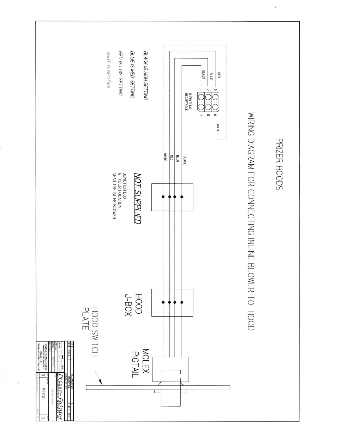
4. Locate the white plastic Moldex electrical connector in the hood. This connector feeds the power to the
remote fan. Use the receptacle connector provided with the fan and plug to the connector in the hood.
Within the J-box, connect the black, white, red and blue wires from the remote fan to the black, white,
red and blue wires of the “pigtail”. Connect the green (ground) wire to the ground wire from the service
panel (see Figure 6.)
Page 7
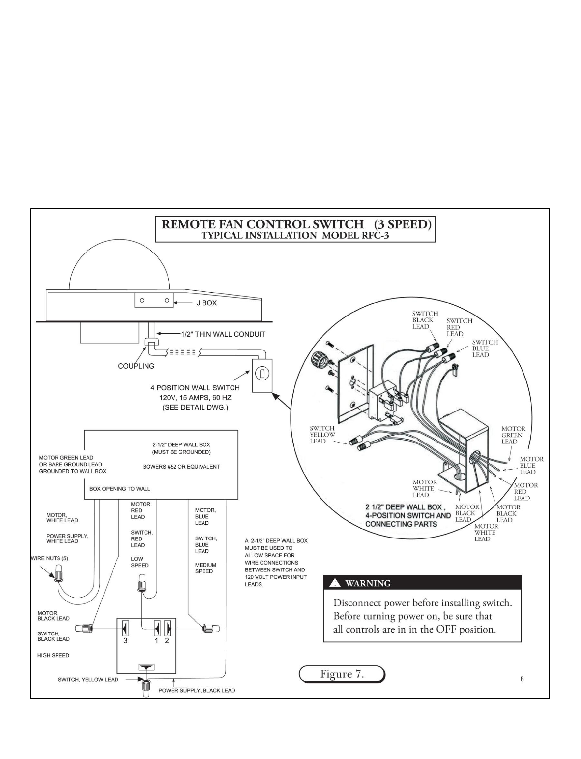
WIRING A WALL-MOUNTED 3-SPEED FAN CONTROL
1. Use 4 Position switch (OFF – LOW – MED – HIGH).
2. Power supply required for these ventilators is 15 amps. @120V. AC, 60Hz. connected per local codes.
3. Run three #14 AWG wires (black, white and green) from the power supply at the electrical circuit panel
to the wall box (see Figure 7).
4. Run electrical conduit per local code from wall box to bottom of remote fan as shown (see Figure 7).
5. Run five #14 AWG wires in conduit between ventilator J-box and 4 position switch. Use color coded
wires corresponding to colors shown (see Figure 7).
6. Use wire nuts to connect wires as shown (see Figure 7).
Page 8
Page 9

INLINE BLOWER INSTALLATION FOR INLB300, INLB600 & INLB1200
WARNING: ELECTRICAL CONNECTIONS SHOULD ONLY BE MADE BY A LICENSED ELECTRICIAN
NOTE: All models use the same housing/enclose
1. Before making any electrical connection make sure your electric is turned off
2. Check that the fan’s impeller is moving freely
3. Unit is designed to be mounted in any position
4. For ideal implementation, close proximity of the blower to its discharge point will improve the unit’s
performance
5. Accessibility to the unit location is important in the planned duct run.
6. When unit is not in its ideal location use larger duct work for longer runs.
7. Sheet metal screws are provided for “L” bracket attachment to the housing. Screws must be positioned
within 1” of the edge of the housing.
8. Seal all ducting connections with cold weather metal tape.
9. The unit should be hung on the “L” brackets using wood screws (not provided).
10. Rubber padding may be added to the insulation of the unit to reduce/eliminate potential vibrations (not
provided).
CLEANING
1. Periodically check exhaust exit for blockage, i.e., bird nests, leaves, etc
2. Periodically inspect the unit ducting and the ventilation exit point for grease build-up
3. If present in the installation, periodically check the dapper for any obstructions.
Page 10
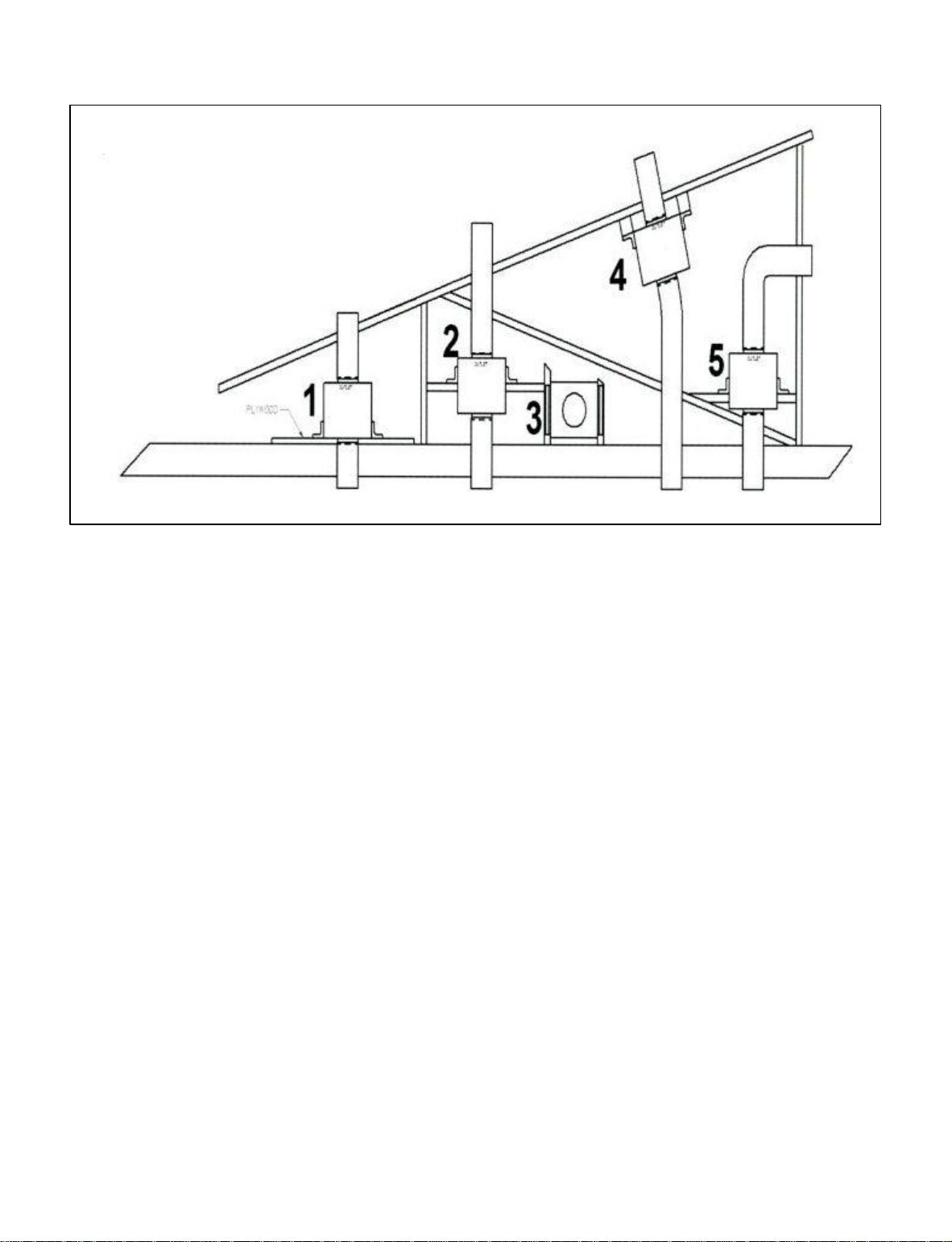
INSTALLATION - POSITIONS
WARNING
1. Use ¾” plywood to mount and separate from ceiling joists bed.
2. Install additional support cross members to truss for a suspended mount.
3. Install additional support cross members to truss for horizontal mounting.
4. Install additional blocking to mount under the roof rafter.
5. Install additional cross members to ceiling joists with a 90 degree elbow to exit side.
Important Notes:
• Adding plywood to each installation may simplify install.
• 10” diameter ducting is recommended for optimal performance of this product. 8” diameter may be used
if ducting space is limited but this may reduce the unit’s performance.
Page 11
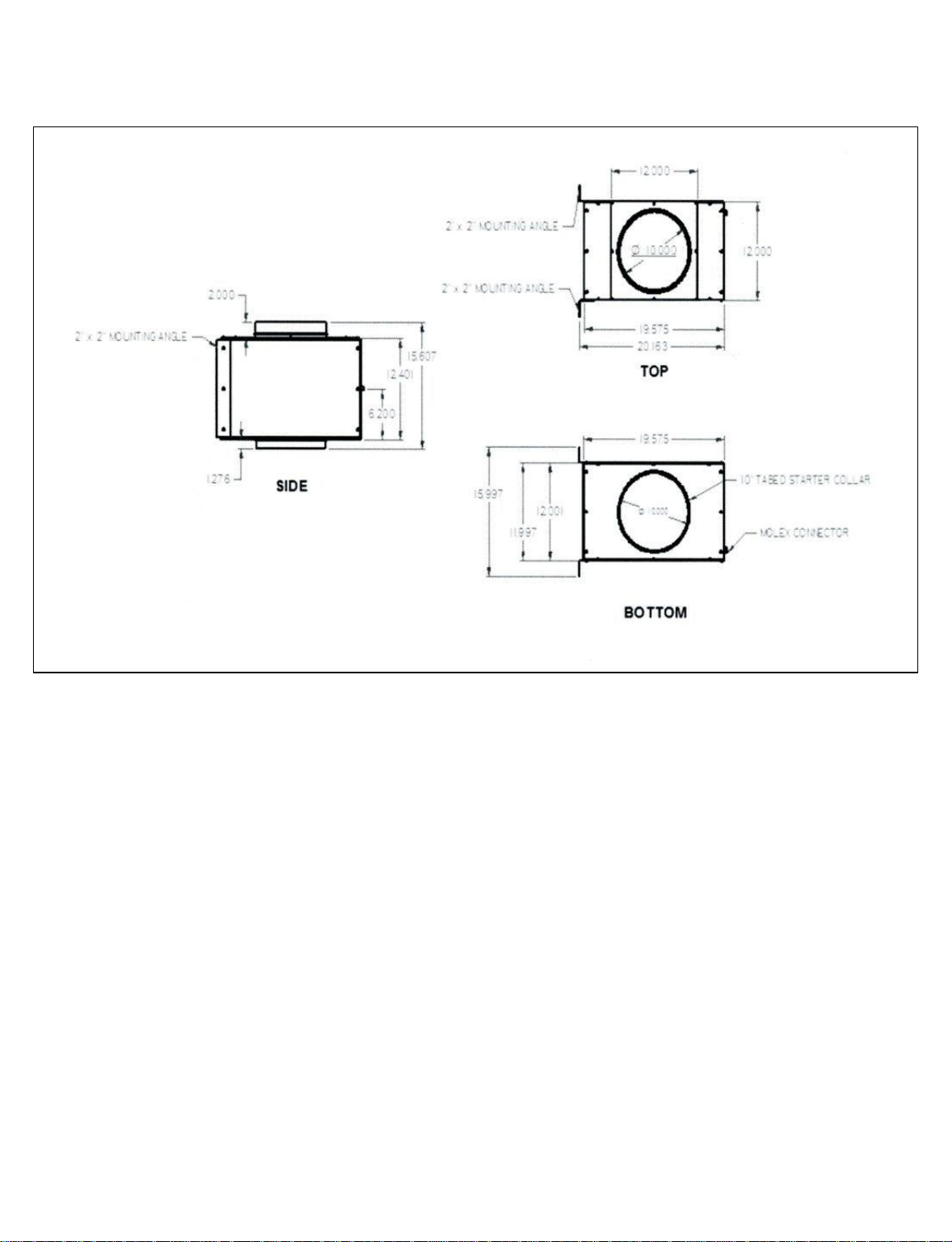
INSTALLATION - SPECIFICATIONS
Page 12
Page 13

INSTALLATION MUST COMPLY WITH ALL LOCAL CODES
KITCHEN VENTILATION TIPS
1. Cooking appliances such as ranges, cooktops,
barbecue units, grill, etc, require adequate ventilation.
Hood should be large enough and cooking
appliances located so that the hood overhangs the
cooking surface as much as possible.
2. Consult a competent kitchen designer or ventilation
engineer for proper hood size and CFM requirements.
3. Provide make-up air input to the kitchen so exhausted
air is not drawn through the furnace unit or down
through the chimney.
4. Locate the cooking area away from doors and
windows for minimum cross drafts when possible.
5. For best performance, duct runs should be as short
and as straight as possible. When turns are necessary
keep turning radius as large and as smooth as
possible.
WARNING – TO REDUCE THE RISK OF A
RANGE TOP GREASE FIRE:
a) Never leave surface units unattended at high settings.
Boil overs cause smoking and greasy spillovers that
may ignite. Heat oils slowly on low or medium
settings.
b) Always turn hood ON when cooking at high heat or
when flaming foods.
c) Clean ventilating fans frequently. Grease should not
be allowed to accumulate on fan or filter.
d) Always use cookware appropriate for the size of the
surface element.
Prizer Hoods reserves the right to change specifications or design without notice. Some models are certified for
use in Canada. Prizer Hoods is not responsible for products which are transported from the United States for use
in Canada. Check with your local Canadian distributor or dealer.
 Loading...