


SOLAR BOOST 3024i
SOLAR BOOST™ 3024i
30AMP 12/24VDC MAXIMUM POWER POINT TRACKING
PHOTOVOLTAIC CHARGE CONTROLLER
INSTALLATION AND OPERATION
MANUAL
THIS MANUAL INCLUDES IMPORTANT SAFETY INSTRUCTIONS FOR
MODEL SB3024i. SAVE THESE INSTRUCTIONS.
COVERED UNDER ONE OR MORE OF THE FOLLOWING US PATENTS
© Blue Sky Energy, Inc. 2005 430-0018 C
6,111,391 • 6,204,645

Blue Sky Energy - Solar Boost 3024i
TABLE OF CONTENTS
IMPORTANT SAFETY INSTRUCTIONS ............................................................................................. 2
PRODUCT DESCRIPTION .................................................................................................................. 3
Part Numbers and Options..................................................................................................... 3
OPERATION ........................................................................................................................................ 3
Optional Remote Displays...................................................................................................... 3
Charge Status Indicator ......................................................................................................... 4
Three Stage Charge Control .................................................................................................. 4
Bulk Charge........................................................................................................ 4
Acceptance Charge............................................................................................ 5
Float Charge....................................................................................................... ..5
Two Stage Charge Control..................................................................................................... 5
Equalization............................................................................................................................ 5
Equalize Time Accumulator ............................................................................... 5
Automatic Equalization....................................................................................... 5
Manual Equalization........................................................................................... 6
Optional Temperature Compensation.................................................................................... 6
Maximum Setpoint Voltage Limit............................................................................................ 6
Temperature and Output Power............................................................................................. 6
Maximum Power Point Tracking (MPPT)............................................................................... 6
How MPPT Works .............................................................................................. 7
Multiple Charge Controllers On The IPN Network ................................................................. 7
INSTALLATION ................................................................................................................................... 7
Over Voltage / Reverse Polarity Protection ........................................................................... 7
Electrostatic Handling Precautions ........................................................................................ 7
Solar Boost 3024i Setup ........................................................................................................ 8
Default Factory Settings..................................................................................... 8
Basic Settings..................................................................................................... 9
Advanced Settings ............................................................................................. 9
Restoring Default Settings ................................................................................. 9
Battery And PV Voltage...................................................................................... 9
Charge Mode...................................................................................................... 10
Acceptance Charge Voltage .............................................................................. 10
Float Charge Voltage ......................................................................................... 10
Acceptance Charge Time................................................................................... 10
IPN Network Address......................................................................................... 10
Battery and PV Wiring............................................................................................................ 11
24V Input / 12V Output........................................................................................................... 11
Battery Temperature Sensor.................................................................................................. 11
Auxiliary Output...................................................................................................................... 12
Auxiliary Battery Charge .................................................................................... 12
Load Controller................................................................................................... 12
Installing a Multi-Controller System ....................................................................................... 13
Multi-Controller Wiring And Setup...................................................................... 13
IPN Network ....................................................................................................... 13
Auxiliary Output In Multi-Controller Systems...................................................... 13
Mounting ................................................................................................................................ 14
TROUBLESHOOTING GUIDE
SPECIFICATIONS
TWO YEAR LIMITED WARRANTY
TABLES AND FIGURES
Table 1 Charge Status Indicator ..................................................................................... 4
Table 2 Maximum Conductor Length - 3% Voltage Drop................................................ 11
Figure 1 Front Panel and Remote Display Indicators....................................................... 4
Figure 2 Factory Charge Voltage Setpoint -vs.- Battery Temperature............................. 6
Figure 3 Setup and Wiring Diagram ................................................................................. 8
Figure 4 Auxiliary Output Wiring....................................................................................... 12
Figure 5 IPN Network Wiring ............................................................................................ 13
Figure 6 Detailed Dimensional Drawing ........................................................................... 13
............................................................................................................................... 17
............................................................................................................. 15
..................................................................................................... 18
1
Installation and Operation Manual
IMPORTANT SAFETY INSTRUCTIONS
This manual contains important instructions for Model SB3024i
SAVE THESE INSTRUCTIONS
1. Refer installation and servicing to qualified service personnel. High voltage is present inside unit. Incorrect installation or use
may result in risk of electric shock or fire. No user serviceable parts in this unit.
2. To reduce the risk of electric shock, fire or personal injury, the following symbols are placed throughout this manual to indicate
dangerous conditions, or important safety or operational instructions.
WARNING CAUTION IMPORTANT
Indicates dangerous conditions or
electric shock potential. Use extreme
caution.
3. PERSONAL PRECAUTIONS
a) Working in the vicinity of lead-acid batteries is dangerous. Batteries produce explosive gasses during normal operation.
b) To reduce risk of battery explosion, follow these instructions and those published by battery manufacturer and manufacturer
of any equipment you intend to use in vicinity of battery.
c) Someone should be within range of your voice or close enough to come to your aid when you work near a lead-acid battery.
d) Have plenty of fresh water and soap nearby in case battery acid contacts skin, clothing or eyes.
e) Wear complete eye protection and clothing protection. Avoid touching eyes while working near battery.
f) If battery acid contacts skin or clothing, wash immediately with soap and water. If acid enters eye, immediately flood eye
with running cold water for at least 10 minutes and get medical attention immediately.
g) NEVER SMOKE or allow a spark or flame in vicinity of battery.
h) Be extra cautious to reduce risk of dropping metal tool onto battery. It might spark or short circuit battery or other electrical
part that may cause explosion.
i) Remove personal metal items such as rings, bracelets and watches when working with a lead-acid battery. A lead-acid
battery can produce a short circuit current high enough to weld a ring or the like to metal, causing a severe burn.
j) Remove all sources of power, photovoltaic and battery before servicing or installing.
4. CHARGER LOCATION & INSTALLATION
a) This unit is designed to charge flooded or sealed type lead-acid chemistry batteries. Follow battery manufacturers charging
recommendations when considering this unit for use with other battery chemistry, i.e., NiCd.
b) This unit employs components that tend to produce arcs or sparks. NEVER install in battery compartment or in the
presence of explosive gases.
c) This unit must be installed and wired in accordance with National Electrical Code, ANSI/NFPA 70.
d) Over current protection for the battery must be provided externally. To reduce the risk of fire, connect to a circuit provided
with 40 amperes maximum branch-circuit over current protection in accordance with National Electrical Code, ANSI/NFPA
70.
e) Over current protection for the auxiliary load control output or auxiliary battery charge output must be provided externally.
To reduce the risk of fire, connect to load or auxiliary battery with 25 amperes maximum over current protection in
accordance with National Electrical Code, ANSI/NFPA 70.
f) Insure that unit is properly configured for the battery being charged.
g) Unit is not water tight. Do not expose to rain or snow.
h) Insure all terminating connections are clean and tight. Battery and PV compression terminals are to be tightened to 45 in-lb
(5 nm). IPN Network and battery temperature sensor compression terminals are to be tightened to 2.1 in-lb (0.24 nm).
Auxiliary output compression terminals are to be tightened to 6 in-lb (0.67 nm).
i) Charging system must be properly installed as described in these instructions prior to operation.
j) Do not connect to a PV array capable of producing greater than 24 amps of short circuit current @ 25°C. Limit input short
circuit current to 12 amps if the 24V input 12V output mode is used.
Indicates items critical to safe
installation or operation of the unit.
Follow these instructions closely for
proper operation of the unit
5. PREPARING TO CHARGE
a) Never charge a frozen battery.
b) Be sure battery is mounted in a well ventilated compartment.
c) Add distilled water in each cell of a lead-acid battery until battery acid reaches level specified by battery manufacturer. This
helps purge excessive gas from the cells. Do not overfill. For batteries other than flooded lead-acid type, or sealed batteries
without cell caps, carefully follow manufacturers charging instructions.
2

Blue Sky Energy - Solar Boost 3024i
PRODUCT DESCRIPTION
Solar Boost™ 3024i a 30 amp 12/24 volt Maximum Power Point Tracking (MPPT) photovoltaic (PV) battery charge controller.
Through the use of patented MPPT technology, Solar Boost 3024i can increase charge current up to 30% or more compared to
conventional controllers. Solar Boost 3024i’s sophisticated three stage charge control system can be configured to optimize charge
parameters to precise battery requirements. The unit is fully protected against voltage transients, over temperature, over current,
reverse battery and reverse PV connections. An automatic current limit feature allows use of the full 30 amp capability without
worrying about overload or nuisance fuse blow from excessive current. An auxiliary output provides either voltage or amp-hour
based 20 amp load control, or can serve as a 2 amp auxiliary battery charger.
Series pass Pulse Width Modulation (PWM) charge voltage control combined with a multistage charge control algorithm leads
to superior charging and enhanced battery performance. The filtered PWM power control system uses highly efficient and reliable
power MOSFET transistors. The MOSFET’s are turned on and off at high frequency to precisely control charge voltage and MPPT.
An environmentally sealed high current high reliability relay is used to disconnect the PV array at night to prevent unwanted current
drain. A relay is used rather than blocking diodes for improved power conversion efficiency, current boost performance, and true
reverse battery polarity protection in an MPPT controller.
Fully automatic temperature compensation of charge voltage is available as an option to further improve charge control and
battery performance. The available battery temperature sensor is built for long term reliability. The sensor element is
environmentally sealed and encapsulated into a copper lug which mounts directly to the battery terminal.
The Solar Boost 3024i also includes an IPN Network interface. The IPN interface allows multiple IPN compatible charge
controllers to communicate with each other and operate as a single machine rather than separate charge controllers. The IPN
interface also provides connection to optional IPN compatible remote displays. The full featured IPN-ProRemote provides
enhanced charge controller setup, monitoring and control. It also provides a complete battery system monitor with amp-hour
counting and a highly accurate remaining battery capacity “fuel gage” type indicator.
PART NUMBERS AND OPTIONS
• SB3024i...............................Solar Boost 3024i controller
• IPNREMOTE.......................IPN-Remote, Low cost LED Bargraph IPN charge control monitor w/25’ cable
• IPNPRO ..............................IPN-ProRemote, Full featured IPN charge control and battery system monitor w/25’ cable
• IPNPRO-S...........................IPN-ProRemote with 500A/50mV current shunt
• CS-500 ................................500A/50mV current shunt
OPERATION
Once installed and configured, charge control and MPPT operations are fully automatic. Charge turns on whenever the PV
array is capable of producing ≈0.25 amps at 2V greater than battery voltage. When PV charge is on the Charge Status LED will
indicate the present charge mode, and indicate when the battery has become highly charged. At night when PV power
production stops, the PV array is disconnected from the battery to prevent unwanted current drain. Note that there is a 5 second
turn-on delay, and a 45 second turn-off delay.
¾ The unit operates on battery power, not PV power. A battery must be connected with a minimum voltage
OPTIONAL REMOTE DISPLAYS
There are two available displays, the very low cost IPN-Remote and the full featured IPN-ProRemote. The IPN-Remote is a basic
LED bargraph type voltage, current and charge mode display without setup or control capability.
setup and monitoring of IPN devices on an IPN network. The IPN-ProRemote provides the ability to access additional setup
parameters and adjust setup parameters to wider ranges that those available with the Solar Boost 3024i alone.
of 9V for the unit to operate.
Solar Boost 3024i uses an IPN compatible display which can monitor up to 8 charge controllers on a single IPN network.
The full featured IPN-ProRemote incorporates a multi-line backlit LCD display and three function keys to provide enhanced
The IPN-ProRemote also provides complete battery system monitoring and eliminates the need for a separate battery
monitor. Some of the many displays provided include; battery voltage, net battery current, net battery amp-hours, highly accurate
battery capacity “fuel gage”, PV amp-hours, min/max battery voltage, auxiliary battery voltage, load control status and much more.
With the IPN-ProRemote, the Solar Boost 3024i can be configured to determine the end-of-charge based on net battery current
matched to battery capacity in amp-hours to provide the most highly optimized charge process.
3
Installation and Operation Manual
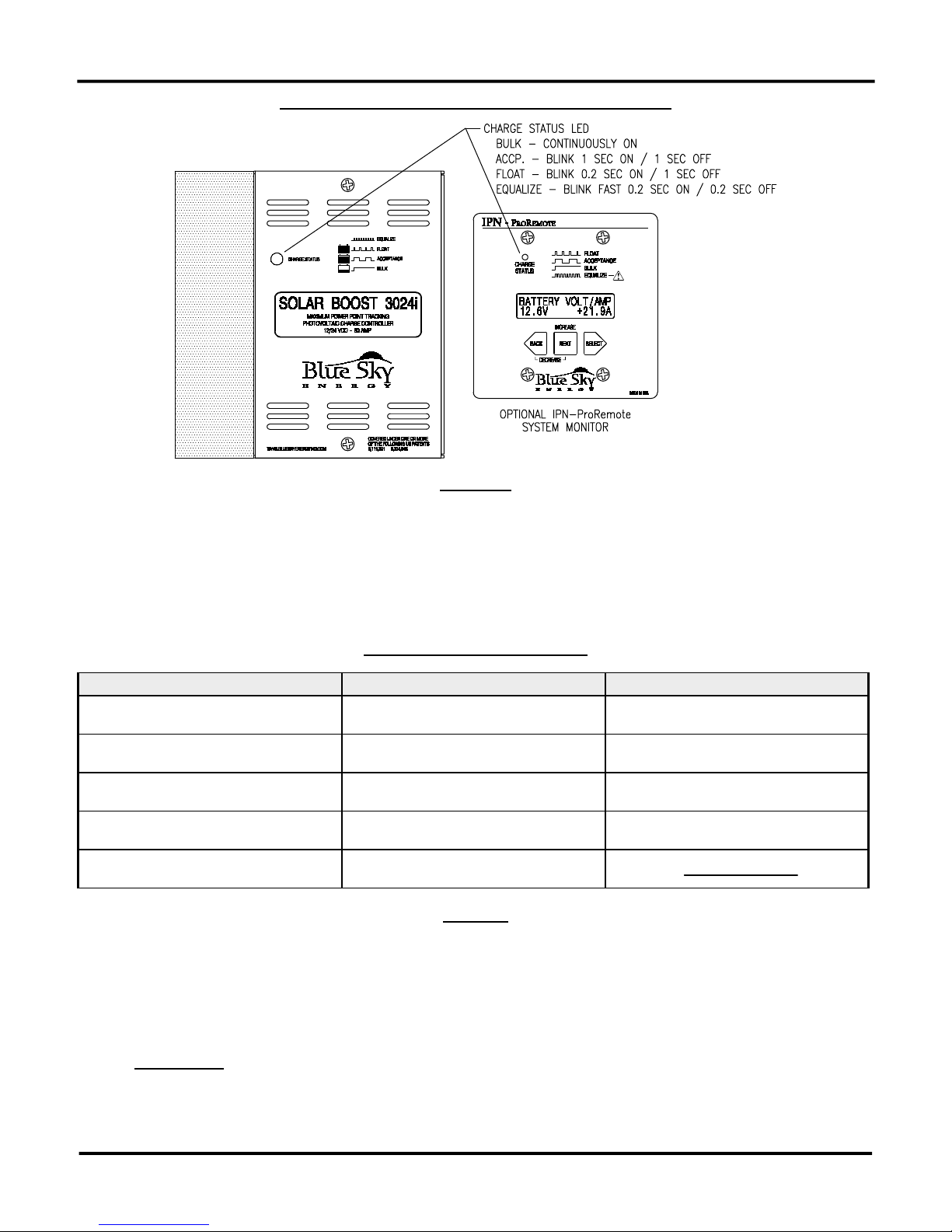
FRONT PANEL AND REMOTE DISPLAY INDICATORS
FIGURE 1
CHARGE STATUS INDICATOR
An LED charge status indicator is provided on the face of the unit, and on the IPN-Remote and IPN-ProRemote displays. The
LED will be off when the unit is not charging, and will be on solid or blinking when the unit is charging the battery. If the PV array is
capable of delivering greater than approximately 3 to 5 amps per 100 amp-hours of battery capacity, the charge status LED can
provide a rough approximation of battery state of charge as shown in the table below.
CHARGE STATUS INDICATOR
STATUS LED CHARGE MODE APPROXIMATE CHARGE LEVEL
OFF
[0]
CONTINUOUSLY ON
[1]
BLINKING
1 SEC ON [1] / 1 SEC OFF [0]
BLINKING
0.1 SEC ON [1] / 1 SEC OFF [0]
BLINKING RAPIDLY
0.1 SEC ON [1] / 0.1 SEC OFF [0]
CHARGE OFF NOT DISPLAYED
BULK <70% FULL
ACCEPTANCE 70% - 95% FULL
FLOAT FULLY CHARGED
EQUALIZE
TABLE 1
THREE STAGE CHARGE CONTROL
Solar Boost 3024i is typically configured for a three stage charging process, Bulk, Acceptance and Float. The three stage
charge process provides a somewhat higher charge voltage to charge the battery quickly and safely. Once the battery is fully
charged a somewhat lower voltage is applied maintain the battery in a fully charged state without excessive water loss. The
three stage charge process charges the battery as quickly as possible while minimizing battery water loss and maintenance.
Bulk Charge
When charge starts the Solar Boost 3024i attempts to apply the Acceptance charge voltage to the battery. The system will
switch to Bulk charge if the battery is sufficiently discharged and/or insufficient charge current is available to drive the battery up to
the Acceptance voltage setpoint. During the Bulk charge stage the unit delivers as much charge current as possible to rapidly
recharge the battery. Once the charge control system enters Acceptance or Float, the unit will again switch to Bulk charge if
4
Blue Sky Energy - Solar Boost 3024i
battery voltage drops below the present charge voltage setpoint. Fully automatic electronic current limit prevents the possibility of
overload by limiting output current to 30 amps regardless of PV input current or power.
Acceptance Charge
As the battery charges in Bulk, battery voltage slowly rises as the battery recovers charge. When sufficient charge has been
recovered for battery voltage to reach the Acceptance voltage setpoint, the unit changes to a constant voltage mode where the
Acceptance voltage is applied to the battery. The Acceptance voltage is factory set to 14.4/28.8V. In Acceptance the battery is
typically between 70% to 95% charged depending on battery size and available charge current.
The battery remains at the Acceptance voltage until it is fully charged and switches to Float as determined by either;
1. Battery voltage has been continuously at (or above) the Acceptance voltage setpoint for the Charge Time period.
(factory default = 2 hours)
– OR –
2. With the IPN-ProRemote display, net battery charge current drops below the Float Transition Current while the
battery is at (or above) the Acceptance voltage setpoint. (factory default = 1.5A per 100 amp-hours)
Float Charge
Once the battery is fully charged the unit switches to Float where the Float voltage is applied to the battery to maintain it in
a fully charged state without excessive water loss. The Float voltage is factory set to 13.4/26.8V. During Float a healthy fully
charged lead-acid battery will draw approximately 0.1–0.2 amps per 100 amp-hours of battery capacity.
TWO STAGE CHARGE CONTROL
Certain battery types or system configurations may require two stage charge control. Solar Boost 3024i can be configured for
a two stage bulk-acceptance charge to accommodate these batteries or systems. Two stage charge is selected by setting the Float
charge voltage setting to No Float. Refer to the Solar Boost 3024i Setup section to configure two stage charge.
EQUALIZATION
¾ WARNING:
vented liquid electrolyte lead-acid batteries. Follow battery manufacturers recommendations pertaining
to equalization.
The Solar Boost 3024i can perform equalization manually or automatically. Since each cell of a battery is not identical,
repeated charge/discharge cycles can lead to an imbalance in the specific gravity of individual cells and electrolyte stratification.
Equalization is essentially a controlled overcharge which brings all battery cells up to the same specific gravity and eliminates
stratification by heavily gassing the battery. While equalization parameters are adjustable with the IPN-ProRemote, factory default
parameters of 15.2/30.4V for 2 hours every 30 days are suitable for most applications. Note that for proper equalization a minimum
net charge current of approximately 3 amps per 100 amp-hours of battery capacity is required. If insufficient current is available
equalization may have to be canceled manually since the equalization time accumulator may not be able to complete count down.
¾
CAUTION:
producing heavy battery gassing. While the Solar Boost 3024i can be configured for manual or
automatic equalization it is strongly recommended that a qualified operator always plan and monitor the
process. The operator should ensure that connected equipment can tolerate the high equalization
voltage which is factory set to 15.2/30.4V. Since the Equalization voltage is temperature compensated,
the voltage can be quite high at cool temperatures if temperature compensation is used.
Equalize Time Accumulator
The equalize time period is not a simple timer but rather a “time at voltage” time accumulator. The equalization timer will not
count down unless the battery is at (or above) the equalization voltage setpoint for the required time period to assure that a proper
equalization cycle has taken place. This is particularly beneficial on systems where the battery or loads are large relative to
available charge current. The equalize time accumulator counts in 3 minute increments. If battery voltage reached the equalization
voltage setpoint during a given 3 minute period, that period is considered good. Unless manually disabled, the unit will stay in
equalize for as long as it takes to accumulate the required time at voltage. This may take hours or even days. If equalize does not
complete by the time the charging day ends, it will pick up where it left off when the next charging day begins.
Not all batteries can be safely equalized. Equalization should only be performed on
Equalization is a controlled over charge of the battery at a relatively high voltage
Automatic Equalization
If DIP switch #5 is turned ON prior to the application of battery power, automatic equalization is enabled. From then on the
unit will perform automatic equalization after the set number of days has elapsed (factory default = 30 days).
5
 Loading...