

Page 1
Marine Electrical Prod
ucts
DC Power Distribution Panel
PN 8272 / PN 8372 4 Position Water Resistant
PN 8271 / PN 8371 8 Position Water Resistant
Panel Specications
Voltage Rating: Panels are rated for 12 or 24 Volts DC
Amperage Rating: Switches and Circuit Breakers:
20 Amperes maximum for 12 Volt systems
15 Amperes maximum for 24 Volt systems
Cumulative Rating: 45 Amperes
Circuit Indicator: LED embedded in switch, rated 100,000 hour 1/2 life
Material: 0.100" 5052-H32 Aluminum Alloy
Primary Finish: Chemical Treatment per MIL-SPEC C-5541
Final Panel Finish: White/Black color 2 part textured Polyurethane
Panel Depth: 2-3/4" 69.90mm
PN Inches Millimeters
Overall Dimensions: 8271/8371 9-3/8 x 4-1/4 238.00 x 108.00
8272/8372 5-1/4 x 4-1/4 133.40 x 108.00
Mounting Centers: 8271/8371 8-17/32 x 3-13/32 216.90 x 86.90
8272/8372 4-13/32 x 3-13/32 112.30 x 86.90
Water Resistant: Will withstand the water exposures normally
The Purpose of a Panel
There are ve purposes of a marine electrical panel:
• Power distribution
• Circuit (wire) protection
• Circuit ON/OFF switching
• Metering of voltage and amperage (panels with meters)
• Condition Indication (circuit energized)
encountered in above deck applications: Salt spray,
rain, hose washdowns, momentary immersions.
WARNING
] These instructions are intended to provide assistance with the
installation of this product, and are not a substitute for a more
comprehensive understanding of electrical systems. We strongly
recommend that a competent electrical professional perform the
installation of this product.
]If the panel front is to be exposed to water it must be properly sealed to
the instrument panel surface. The included gasket must be in place
and the panel screwed down tight.
]The panels must not be installed in explosive environments such as
gas engine rooms or battery compartments as the switches are not
ignition proof.
]The main positive connection must be disconnected at the battery post
to avoid the possibility of a short circuit during the installation of this
distribution panel.
Guarantee
Any Blue Sea Systems product with which a customer is not satised
may be returned for a refund or replacement at any time.
Useful Reference Books
• Calder, Nigel (2005). Boatowner’s Mechanical and Electrical Manual
(3d ed). Camden, ME: International Marine / McGraw-Hill.
• Wing, Charlie (2006). Boatowner’s Illustrated Electrical Handbook
(2d ed). Camden, ME: International Marine / McGraw-Hill.
Other Innovative Products from Blue Sea Systems
• 360 Panel System
• Battery Management Solutions
• AC and DC circuit protection devices
• WeatherDeck™ waterproof panels
• Fuses, fuse blocks, and BusBars
• Analog and digital meters
9111 Rev.005
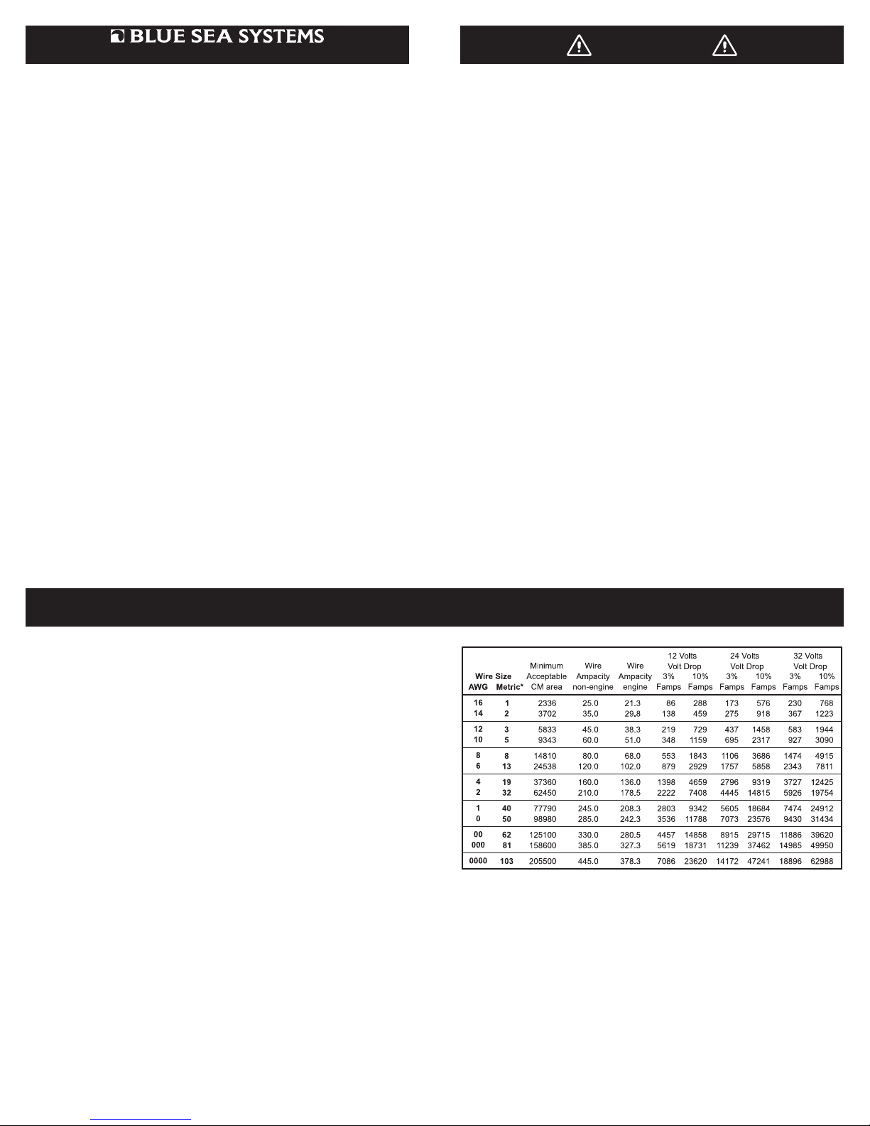
Wire Sizing Chart
1. Calculate the maximum sustained amperage of the circuit. Measure
the length of the circuit from the power source to the load and back.
2. Decide whether the circuit runs in an or . Engine spaces are assumed
to be at 50 degrees C, non engine spaces are assumed to
be at 30 degrees C.
3. Multiply the maximum current times the length of the circuit to calculate
(Feet x amps).
4. Base the wire on either the 3% or 10% . In general, items
which affect the safe operation of the boat and its passengers (running
lights, bilge blowers, electronics and distribution panel supply circuits)
use 3%; all other loads use 10% (cabin lights, bait pumps).
5. Starting in the column which has the right and
shown at the top, run down the list of numbers until arriving at a value
which is greater than the calculated . Move left to the
column to verify that the total amperage of the circuit does not exceed
the maximum allowable amperage of the wire size for that row. If it
does, move down until the wire ampacity exceeds the circuit
amperage. Finally, move left to the column to select the wire
size.
Note: This chart assumes wire with 105°C insulation rating and AWG wire sizes.
*Metric wire sizes may be used if of equivalent circular mil area.
a. A 12 Volt system at 10% drop with a 40' circuit x 45 Amps = 1800
Famps. A wire size of 8 is required.
b. A 24 Volt system at 3% drop with a 10' circuit x 100 Amps = 1000
Famps. A wire size of 6 is required.
Blue Sea Systems Inc. Phone (360) 738-8230
425 Sequoia Drive Fax (360) 734-4195
Bellingham, WA 98226 USA www.bluesea.com
Page 2
Installation
1. Disconnect all AC and DC power
Before starting, disconnect the main positive cable from all batteries to
eliminate the possibility of a short circuit while installing the distribution
panel. Also disconnect the AC shore power cord from the boat to
eliminate the possibility of electrocution from AC wiring in the proximity
of the DC distribution panel.
2. Select mounting location and cut opening
Using the panel template provided, make a cut out in the mounting
surface where the distribution panel is to be mounted. Do not yet
fasten the panel to the mounting surface.
3. Select positive feed wire
Determine the positive feed (red) wire size by calculating the total
amperage of the circuits that will be routed through the panel. Blue Sea
Systems water-resistant electrical panels are rated at 45 amp total
capacity. The positive feed wire must be sized for 3% voltage drop at
the 45 amp panel rating or the maximum amperage that will be routed
through the panel in any particular installation, whichever is less. It is
recommended that the positive feed wire be sized for the full panel
capacity, which, in most cases, will require at least 8 AWG wire,
assuming a 10 foot wire run between the panel and the batteries in
12 volt systems. Refer to the Wire Sizing Chart for other situations.
Remember that the length of the circuit is the total of the positive wire
from the power source and the negative wire back to the DC Negative
Bus. Be certain that there is a fuse or circuit breaker of the correct size
protecting the positive feed wire.
Use a 16 AWG wire to connect the LED negative feed (yellow) wire to
the DC Negative Bus.
Determine the proper wire size for each branch circuit using the
guidelines in step 3. Verify that the standard 15 ampere circuit breakers
installed in the panel are large enough for each branch circuit.
Remove and replace with a higher amperage any that are undersized
(15 ampere maximum for 24 volt or 20 ampere for 12 volt systems).
Connect a positive (red) branch circuit wire to the load terminal of
each switch. Connect each negative (yellow) branch circuit wire to a
DC Negative Bus such as Blue Sea Systems BusBar PN 2301 or
MiniBus PN 2304.
For each branch circuit, select a label from the 60 basic labels
provided, and apply it to the recessed area on the front of the panel.
A gasket has been included for sealing the panel against the mounting
surface. The gasket will easily stretch around the panel when applied
from the front. Place the gasket between the panel and the mounting
surface. Make sure all surfaces are clean and free from debris.
Fasten the panel to the mounting surface using the screws provided.
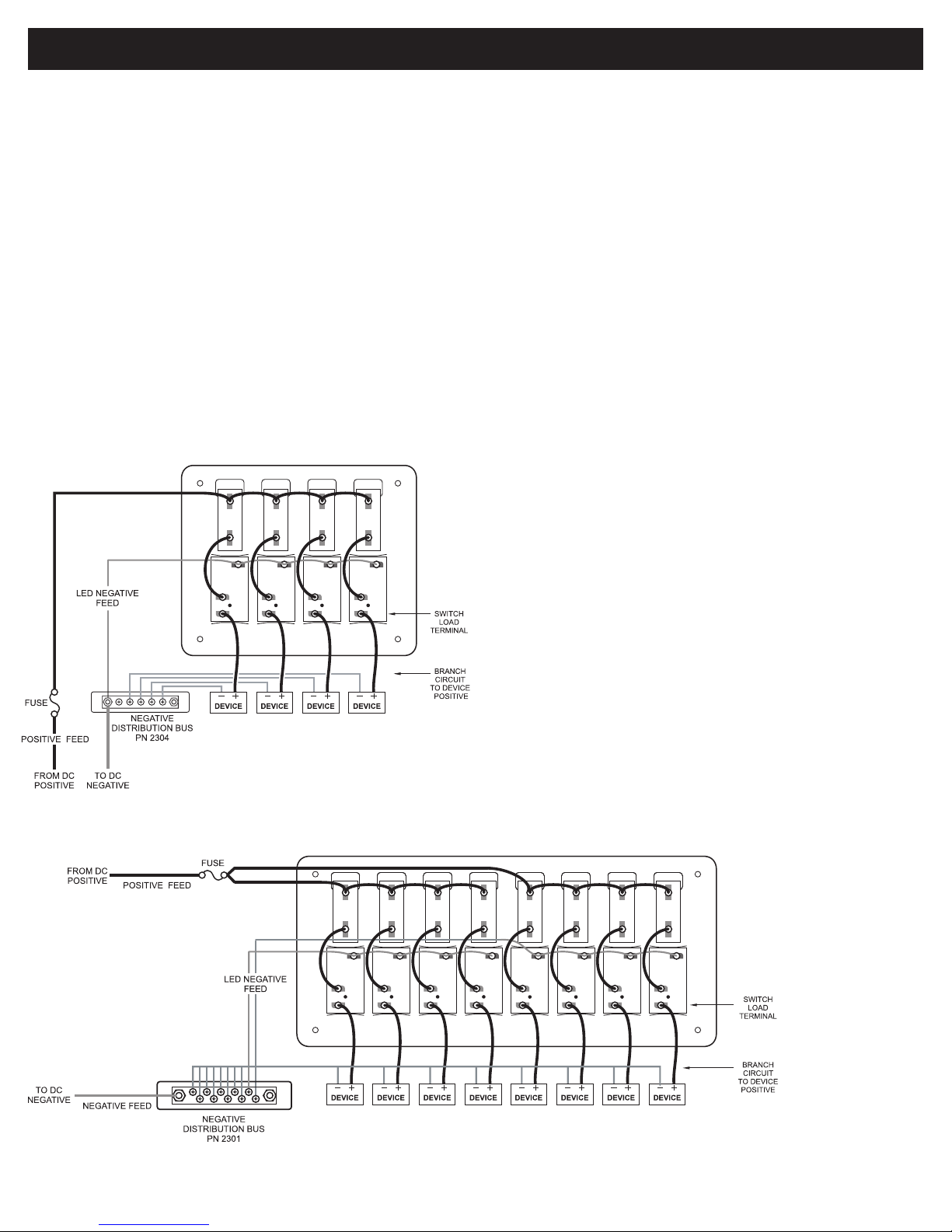
Wiring Diagram
DC Water Resistant Circuit Breaker Panel
PN 8272/8372
Reconnect the main positive cable to the battery terminals and turn the
main switch on to supply power to the panel. Turn on all branch circuits
and test the voltage at the panel. Compare this voltage to the battery
terminal voltage to determine that the voltage drop is within 3%. With
all branch circuits still on, test the voltage at one device on each circuit
to determine that there is a 3% or 10% drop as is appropriate.
This Blue Sea Systems water resistant electrical distribution panel is
furnished with 15 ampere push button circuit breakers. This rating was
selected to minimize the need for removing the circuit breakers and
reinstalling different size circuit breakers. 15 ampere circuit breakers will
satisfy the vast majority of marine circuit protection situations.
• American Boat and Yacht Council (ABYC) Standards and
Recommended Practices for Small Craft sections: E-9.
• United States Coast Guard Code of Federal Regulations 33, Part 183,
Subpart I, Electrical Systems on Boats.
Wiring Diagram
DC Water Resistant Circuit Breaker Panel
PN 8271/8371
 Loading...