

Page 1

Marine Electrical Prod
ucts
DC Battery Switch Panel
Three m-Series Single Circuit ON/OFF Battery Switches
Features
• Isolates Start circuit from House circuit: protects electronics from sags
and spikes caused by engine cranking
• Discharges batteries independently
• Single Circuit ON/OFF battery switch controls House circuit
• Single Circuit ON/OFF battery switch controls engine Start circuit
• Single Circuit ON/OFF battery switch combines House and Start battery
banks for emergency starting (Emergency Cross Connect/Parallel)
• Ignition Protected-Safe for installation aboard gasoline-powered boats
Panel Specifi cations
Material: 0.125” 5052-H32 Aluminum Alloy
Primary Finish: Chemical Treatment per Mil Spec C-5541C
Final Panel Finish: Graphite color 2 part textured Polyurethane
Maximum Voltage Rating: 48V DC
Switch Amperage Ratings: Continuous: 300A
Dimensions: 8280 6.250 x 7.500 158.75 x 190.50
Mounting Centers: 8280 5.420 x 6.670 137.67 x 169.42
Battery Switch Terminal Studs: 3/8”-16 (accepts M10 terminal)
Torque: 140 in-lbs.
PN 8280/8370
Intermittent (5 min.): 500A
Cranking (100 sec.): 700A
Inrush (2.5 sec.): 1500A
Inches Millimeters
8370 9.500 x 4.375 241.30 x 111.13
8370 8.670 x 3.545 220.22 x 90.04
WARNING
@ If the installer is not knowledgeable about electrical systems,
consult an electrical professional.
@ If either the panel front or back is to be exposed to water it must be
protected with a waterproof shield.
@ The main positive connection must be disconnected at the battery post
to avoid the possibility of a short circuit during the installation of
this distribution panel.
Guarantee
If at any time you are not satisfi ed with this product, you may return it
for a refund or replacement.
Useful Reference Books
Calder, Nigel, 2005: Boatowner’s Mechanical and Electrical Manual,
3rd edition, Blue Ridge Summit, PA: TAB Books, Inc.
Wing, Charlie, 1993: Boatowner’s Illustrated Handbook of Wiring,
Blue Ridge Summit, PA: TAB Books, Inc.
Applicable Standards
• American Boat and Yacht Council (ABYC) Standards and Recommended
Practices for Small Craft sections: E-1, E-3, E-11.
• United States Coast Guard 33 CFR Sub Part 1, Electrical Systems.
Engine Starting Standard
Blue Sea Systems’ battery switches, in addition to being tested to UL
1107, are also tested to the Engine Starting Standard by a United States
Coast Guard certifi ed Nationally Recognized Testing Laboratory. The
Standard rates battery switches based on testing under very diffi cult
starting conditions.
How it works Installation
DC Battery Switch Panels PN 8280 and 8370 provide an electrical system
in which the main House circuit and the engine Start circuit are isolated from
each other. Battery isolation protects the Start battery from being discharged
from the many House loads like refrigerators, stereos, and lights, preserving
it for starting the engine. Battery isolation also protects sensitive electronics
from voltage spikes and sags that may occur during engine starting.
Battery switch operation is simplifi ed because the three battery switches
are ON/OFF. The engine and house battery switches are turned ON when
the boat is boarded, and OFF when the boat is not in use. In an emergency
requiring that both battery banks are combined—e.g., a discharged start
battery—the operator switches the Emergency Parallel switch to the ON
position; this combines both Engine and House battery banks.
Charging of two battery banks can be automated by adding an Automatic
Charge Relay (PN 7600 or PN 9112) to the system. This combination creates a complete battery management system of isolated battery circuits,
emergency combine function, and automated charge management.
1. Disconnect all DC power
To eliminate the possibility of a short circuit while installing the panel,
disconnect the main positive cable from all batteries.
2. Select mounting location and cut opening
Select a mounting location that is protected from water on the panel
front and back.
Using the panel template provided, make a cut out in the mounting
surface where the panel is to be mounted. Do not fasten the panel to the
mounting surface.
3. Electrical Connections
Battery cable terminals must be attached under battery switch stud nut
and lock washer. The electrical connection illustration is general in
nature and is not meant to be a guide for the wiring of any specifi c
vessel. There is a wide range of wiring confi gurations possible. Consult
your marine electrical professional for the wiring system applicable to
your boat.
Make appropriate adjustments to the wiring diagram to suit your specifi c
installation and equipment. Fusing may be appropriate in several of the
lines depending on the proximity of components, conductor sheathing,
and the conductivity of the surrounding structure. Consult the Wire
Sizing Chart to determine the appropriate wire sizes.
4. Apply Labels and Mount Panel
Apply a label to each of the circuits from the label sheet provided. Use
the panel mounting screws supplied with the panel to secure the panel
to the mounting surface. Additional labels are available from
Blue Sea Systems.
Page 2
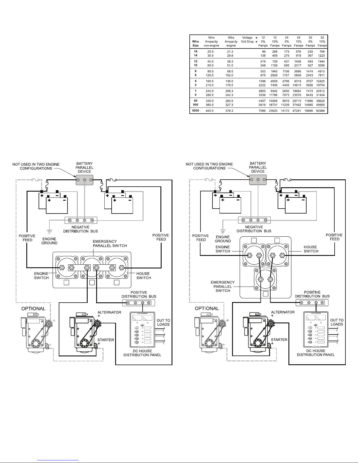
Wire Sizing Chart
1. Calculate the maximum sustained amperage of the circuit. Measure the
length of the circuit from the power source to the load and back.
2. Calculate Famps (Feet x amps). Multiply circuit lenght by max. current.
3. Base the wire on either the 3% or 10% voltage drop. In general, items
that affect the safe operation of the boat and its passengers (running
lights, bilge blowers, electronics) use 3%; all other loads use 10%.
4. Are the circuit runs in an engine space or non-engine space?
5. Starting in the column that has the right voltage and voltage drop,
select a value that is greater than the calculated Famps. Look left to the
Ampacity column to verify that the total amperage of the circiut does
not exceed the maximum allowable amperage of the wire size for
that row. If it does, move down until the wire ampacity exceeds the
circuit amperage. Finally, look left to the wire size column to select the
wire size.
Example
A 12 volt system at 10% drop with a 40’ circuit x 45 amps = 1800 Famps.
A wire size of 8 is required.
ENGINE HOUSE
Note: For wire with 105°C insulation rating and AWG wire sizes.
Chart courtesy of the West Advisor
ENGINE HOUSE
Wiring Diagram
DC Battery Switch Panel
PN 8370
Wiring Diagram
DC Battery Switch Panel
PN 8280
 Loading...