

Page 1
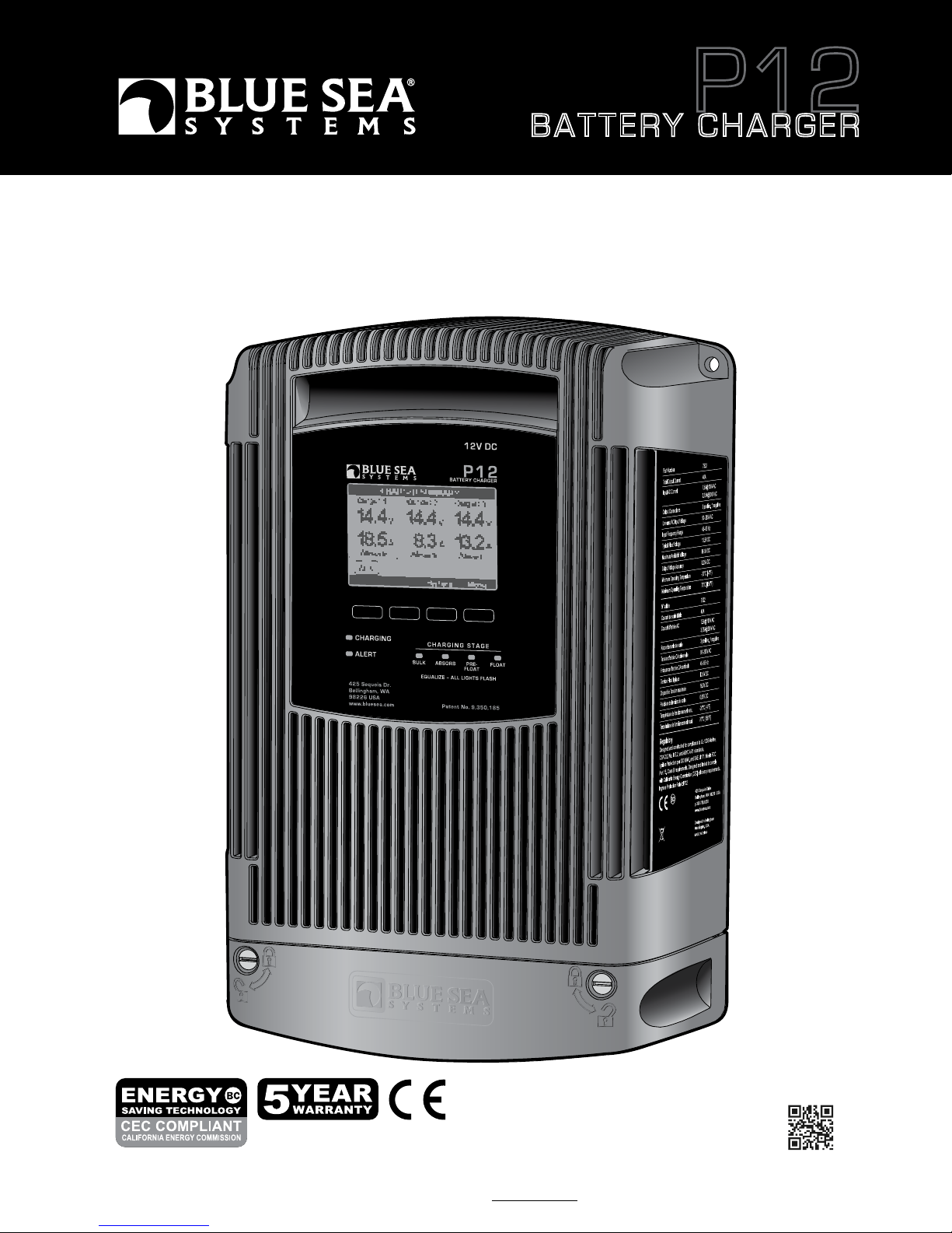
BATTERY CHARGER
User Manual
7531 and 7532
P12
Read and understand the contents of this User Manual. It contains important safety, handling, and operational instructions for P12 Battery Chargers.
This User Manual describes the product mentioned herein at the time of its publication. Specifications and performance are subject to change at the discretion
of Blue Sea Systems. To view the most current revision of this publication visit bluesea.com/P12.
Scan for
additional
product
information
Page 2
Specifications are subject to change. See bluesea.com/P12 for current information.
1
Table of Contents
Important Safety Instructions 1–2
P12 Battery Charger Overview 3–4
Specifications 5
Installation Tables 5
• Table A: Minimum Recommended Wire Size
• Table B: Recommended DC Circuit Protection
• Table C: Typical AC Regional Wire Colors
• Table D: AC Wire - Circuit Protection Selection Chart
• Table E: Default Voltages by Battery Type
Product Dimensions and Installation Clearances 6
Included Components 7
Supplies Needed 8
Installation Instructions 9–10
Initial Charger Setup 11
Advanced Charger Setup 12–13
Reset to Manufacturer Defaults 13
Absorption Parameters and Timers, Energy Save Feature Control 14–15
Temperature Parameters 15
Equalization 16–17
Screen Summary 18–19
Alert Screens and Diagnostics 20–21
Optional Installation 22–23
• Automatic Charging Relays (ACRs)
Warranty and Contact Information 24
P12 Charge Management System 25
WARNING
Refers to a potentially hazardous situation which, if not avoided, could result in death or serious injury.
The P12 Battery Charger should be installed by a qualified marine electrician. Improper installation can result in electrical shock which may cause serious
injury or death. To reduce the risk of electrical shock, mount vertically in a dry, well ventilated location. Charge these battery types: Flooded, AGM, Gel, or
TPPL Lead Acid batteries. Consult battery manufacturer specifications for other battery types to avoid damage. This batter y charger is not intended for use
by persons (including children) with lack of ability, experience, or knowledge, unless they have been given supervision or instruction concerning use of the
battery charger by a person responsible for their safety. Do not recharge non-rechargeable batteries. Children should be supervised to ensure that they do
not play with the appliance. Avoid serious injury or death from electrical shock, turn off AC supply power before opening terminations cover.
Risk of Explosive Gases
Working in the vicinity of a Lead-Acid battery is dangerous. Batteries generate explosive gases during normal battery operation. Explosive gasses can ignite
and may cause serious injury or death. Ensure battery location is properly ventilated according to batter y manufacturer or industry standards. To reduce risk
of battery explosion, follow these instructions and those published by the battery manufacturer. Do not smoke or cause a spark in the area around batteries
and engines. Each time before using your charger read this manual and follow the instructions. Do not use any accessory devices that directly connect to
the charger other than those manufactured by Blue Sea Systems and designed for use with the P12 Battery Charger. Do not operate the charger if it has
been dropped or damaged. Contact Blue Sea Systems on how to proceed. Wear complete eye protection and protective clothing when dealing with lead
acid batteries. Remove personal metal items such as jewelry & rings when working around batteries.
CAUTION
Refers to a potentially hazardous situation which, if not avoided, may result in injury.
Before beginning electrical installation, read the instruction manual. Disconnect all AC and DC power sources. Do not make final connections to the
batteries until DC connections on the charger are made and verified. Do not make or break electrical connections to batteries while charging or for up to
30 minutes after charging. Other than parts accessed under the termination cover, there are no user serviceable parts within the battery charger enclosure.
Contact Blue Sea Systems for servicing. Charge only user selectable type batteries, other types of batteries may burst causing personal injury and damage.
Do not use the battery charger to charge dry cell batteries that are commonly used with home appliance. These batteries may burst and cause injur y to
person and damage to property. Never charge a frozen battery.
GROUNDING PRECAUTIONS
Marine battery chargers and inverters have two grounding connections, one from the AC system and one from the DC system. ABYC requires
the AC grounding system to be connected to the DC grounding system through the distribution systems. Additionally, the chargers make
connections to both systems. It is very important the systems be connected properly before the charger is installed. Otherwise the charger
grounding system may become the sole connection between AC and DC ground and it may not be sized large enough to provide system wide
safety function. The AC grounding conductor is the conductor with green, or green with yellow stripe included in the AC power cable and should
be sized the same as the power and neutral conductors (see Table C page 5 for AC wire color). This will connect to the right most terminal in
the AC connection block. There is also chassis connection terminal for a DC safety grounding wire. The DC safety ground should be green or
marked green and sized equal to, or one wire size smaller, than the DC charge wires.
READ AND SAVE THESE INSTRUCTIONS
1. SAVE THESE INSTRUCTIONS – This manual contains important safety and operating instructions for battery charger Models 7531 and 7532.
2. Do not expose charger to rain or snow.
3. Use of an attachment not recommended or sold by the battery charger manufacturer may result in a risk of fire, electric shock, or injury to persons.
4. Do not operate charger with damaged cord – replace the cord immediately.
5. Do not operate charger if it has received a sharp blow, been dropped, or otherwise damaged in any way; take it to a qualified serviceman.
6. Do not disassemble charger; take it to a qualified serviceman when service or repair is required. Incorrect reassembly may result in a risk of
electric shock or fire.
The battery charger must be properly assembled in accordance with the assembly instruction before it is used.
7. To reduce risk of electric shock, unplug charger from outlet before attempting any maintenance or cleaning. Turning off controls will not reduce this risk.
8.
WARNING – RISK OF EXPLOSIVE GASES.
a) WORKING IN VICINITY OF A LEAD-ACID BATTERY IS DANGEROUS. BATTERIES GENERATE EXPLOSIVE GASES DURING
NORMAL BA
TTERY OPERATION. FOR THIS REASON, IT IS OF UTMOST IMPORTANCE THAT YOU FOLLOW THE INSTRUCTIONS
EACH TIME YOU USE THE CHARGER.
b) To reduce risk of battery explosion, follow these instructions and those published by battery manufacturer and manufacturer of any equipment you
intend to use in vicinity of batter
y. Review cautionary marking on these products and on engine.
9.
PERSONAL PRECAUTIONS
a) Consider having someone close enough by to come to your aid when you work near a lead-acid battery.
b) Ha
ve plenty of fresh water and soap nearby in case battery acid contacts skin, clothing, or eyes.
c)
Wear complete eye protection and clothing protection. Avoid touching eyes while working near battery.
d) If batter
y acid contacts skin or clothing, wash immediately with soap and water. If acid enters eye, immediately flood eye with running cold water for at
least 10 minutes and g
et medical attention immediately.
IMPORTANT SAFETY INSTRUCTIONS
P12
7531 AND 7532 BATTERY CHARGERS
P12
7531 AND 7532 BATTERY CHARGERS
Page 3
Specifications are subject to change. See bluesea.com/P12 for current information. Specifications are subject to change. See bluesea.com/P12 for current information.
IMPORTANT SAFETY INSTRUCTIONS
Warnings
Specifications
Terminations
Display
2
P12
7531 AND 7532 BATTERY CHARGERS
CEC Compliance
The Blue Sea Systems P12 Battery Charger is dry mount device designed for use in marine applications and other harsh environments where
reliability, ease of use, and high performance are of primary importance. The P12 is designed in Bellingham, Washington, USA.
The P12 is designed to charge three electrically independent batteries or battery banks. The P12 has the unique capability to individually move each battery out of the
Absorption charging stage. This ensures batteries near their full charge do not continue to receive high constant voltages necessary in the Absorption stage. This is optimal
treatment for long battery life. Charge Coordination integrates with the Blue Sea Systems family of Automatic Charging Relays (ACR) to force separation of the battery banks
while the P12 is operational, to allow the batteries to individually exit the absorption stage. After fourteen days of continuous Float, the charger will repeat the normal charge
cycle to assure good battery health.
For reliability, the P12 has a rugged cast aluminum housing with high heat dissipating capability for minimum cooling fan run times. The electronic design has given special
consideration to operation in areas of inconsistent AC power quality. The P12 has a Power Factor Corrected nominal AC input range of 115V to 230V AC within which it will
produce its full rated DC charging output. It will continue to produce reduced DC output to as low as 75V AC. After a shut down below 75V AC or when there is interrupted
switching between AC sources, like switching between generator and shore power, the P12 will automatically perform an orderly restart.
Central to the P12’s ease of use is the large plain-language full graphics control screen capable of displaying in French, English, Italian, German and Spanish. The plain
language display enables clear communication with the operator for setting precise charging parameters and providing a broad range of easily understood fault
communications and operating history. An optional remote display brings much of this functionality to a secondary location away from the charger.
The P12 contains charge profiles for most batteries available today, including Flooded Lead Acid (FLA), Gel, Thin Plate Pure Lead (TPPL), and Absorbed Glass Mat (AGM).
In addition, a user configurable charge profile is available for other battery types.
The P12 has built-in safety features including: ignition protection, over and under temperature protection (sensed internally and at the batteries), DC reverse polarity
protection, DC over voltage protection, surge, and short circuit protection.
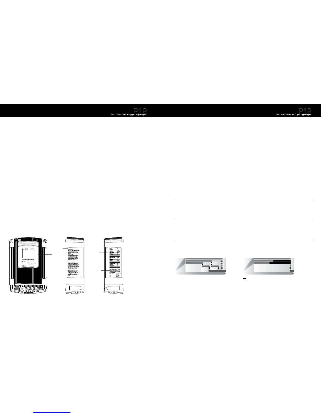
The definitions of the P12 charging stages are defined below. The charging stage LEDs on the front of the charger will indicate the current stage.
Absorption (Constant voltage)
In the Absorption charging stage the batteries complete their charging by being “topped off”. This is a less aggressive charging stage than bulk where the current going into a
particular battery bank will significantly reduce with time. The conditions for a battery bank to be considered “full” var y based on many different factors. In order for a battery
bank to leave the Absorption stage a number of different parameters must be met. The main parameters are the Absorption Timers which can be seen on
page 14. Outputs move individually from Absorption to Pre-Float. When all batteries have completed Absorption, the charger will move them into the Float stage.
Float* (Constant voltage)
Float is the final charging stage for fully charged batteries. Batteries in this stage are being maintained at their defined float voltage. Typically Float voltage
has a 1.0V or greater difference from the Absorption voltage.
Pre-Float (Constant voltage)
The Pre-Float charging stage is unique to the P12. Since the size of battery banks typically vary from one output to the next, there is a need to charge each bank independently.
Once all batteries are in Absorption battery banks may finish charging at different rates. Once a battery bank has met its unique Absorption parameters, the P12 Charger will
independently move it into the Pre-Float stage. Pre-Float is the initial stage to maintain a fully charged battery. Batteries in Pre-Float can have up to a .5V difference
between batteries in Absorption. Up to two outputs can be in Pre-Float simultaneously.
Bulk (Constant current)
The Bulk charging stage is the first stage in the battery charging process. It is where a majority of the charging actually takes place leaving batteries at approximately
75% to 80% of their final capacity. The goal of the Bulk stage is to drive current into the batteries quickly to increase their voltage. Once all the batteries have reached the
defined Absorption voltage then the charger will move them into the Absorption stage.
14.5V
14.0V
T I M E
Absorption
Absorption
Absorption
PreFloat
Bulk
13.5V
Battery 1
Battery 2
Battery 3
PreFloat
Float
Example of Flooded Lead Acid Battery
14.5V
T I M E
Absorption
Bulk
13.5V
Battery 1
Battery 2
Battery 3
Float
Forced Absorption: A period when batteries are potentially over charged.
Example of Flooded Lead Acid Battery
Absorption
Absorption
Forced Absorption
Forced Absorption
Conventional Three Stage Battery ChargingFour Stage Battery Charging
Four Stage Battery Charging
P12 Battery Charger Overview
3
P12
7531 AND 7532 BATTERY CHARGERS
*Energy Saver Mode (CEC)
a) After the absorption cycle is completed for all outputs, the charger moves to “rest” mode – not float.
b) As the battery(s) rests, the voltage will drop. If loads are active, the voltage will drop more rapidly.
c) When the voltage has dropped to the lower target re-float voltage, the charger will re-start and attempt to enter float mode for a minimum of 4 hour s.
d) The charger will enter rest mode again and the cycle will repeat.
NOTE: The CEC test is performed on batteries that have no active loads.
e) NEVER smoke or allow a spark or flame in vicinity of battery or engine.
f) Be extra cautious to reduce risk of dropping a metal tool onto batter
y. It might spark or short-circuit battery or other electrical part that
ma
y cause explosion.
g) Remo
ve personal metal items such as rings, bracelets, necklaces, and watches when working with a lead-acid battery. A lead-acid battery can produce a
shor
t-circuit current high enough to weld a ring or the like to metal, causing a severe burn.
h) Use charger for charging a LEAD-ACID battery only. It is not intended to supply power to a low voltage electrical system other than in a starter-motor
application.
Do not use battery charger for charging dry-cell batteries that are commonly used with home appliances. These batteries may burst and
cause injur
y to persons and damage to property.
i) NEVER charg
e a frozen battery.
10.
PREPARING TO CHARGE
a) If necessar y to remove battery from vessel to charge, always remove grounded terminal from battery first. Make sure all accessories in the vehicle are
off,
so as not to cause an arc.
b) Be sure area around batter
y is well ventilated while battery is being charged.
c) Clean batter
y terminals. Be careful to keep corrosion from coming in contact with eyes.
d) Add distilled water in each cell until batter
y acid reaches level specified by battery manufacturer. Do not overfill. For a battery without removable cell
caps, such as valve regulated lead acid batteries, carefully follow manufacturer’s recharging instructions.
e) Stud
y all battery manufacturer’s specific precautions while charging and recommended rates of charge.
f) Deter
mine voltage of battery by referring to vessel owner’s manual and make sure it matches output rating of battery charger.
11.
CHARGER LOCATION
a) Locate charger as far away from battery as DC cables permit.
b) Ne
ver place charger directly above battery being charged; gases from battery will corrode and damage charger.
c) Ne
ver allow battery acid to drip on charger when reading electrolyte specific gravity or filling battery.
d) Do not operate charg
er in a closed-in area or restrict ventilation in any way.
e) Do not set a batter
y on top of charger.
GROUNDING INSTRUCTIONS – This battery charger should be connected to a grounded, metal, permanent wiring system; or an equipment-grounding
conductor should be run with circuit conductors and connected to equipment-grounding terminal or lead on battery charger. Connections to battery charger
should comply with all local codes and ordinances.
Page 4
Specifications are subject to change. See bluesea.com/P12 for current information. Specifications are subject to change. See bluesea.com/P12 for current information.
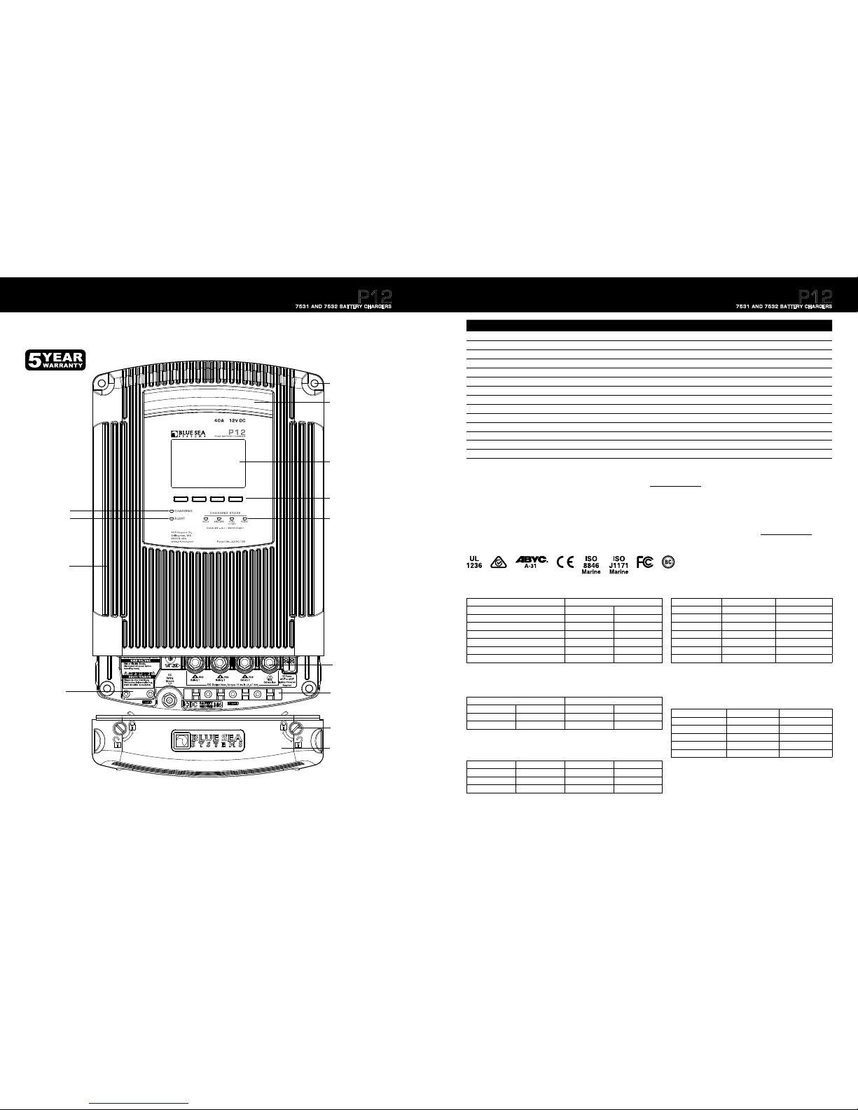
Rugged, finned
cast aluminum case
Fan vent
Screen selection
buttons
Charging stage
indicators
Termination
cover latches
Charging and
Alert indicators
Graphic LCD Display
Termination
insulating
cover
DC output
DC strain
relief clamp
AC strain
relief and
insulating cover.
AC input terminals
under cover.
Mounting holes
Clearance for:
M6, 1/4", or #12
mounting hardware
NOTE: Mounting holes screw
centers are not symmetrical.
Please see dimension drawing
on page 6
P12 Battery Charger Overview
4
P12
7531 AND 7532 BATTERY CHARGERS
Specifications
5
* Consult battery manufacturer specifications for other battery types to avoid damage. Do not mix battery types.
** Battery bank sizes are tested to California Energy Commission compliance (CEC). Larger and smaller size banks could charge well, but consume slightly
more power over the charging cycle.
Regulatory
Designed and constructed for compliance to UL-1236 Marine, CSA 22.2 No. 107.2, and ABYC A-31 standards.
CE Marked
Ignition Protection per ISO 8846 and SAE J1171. Meets FCC Part 15, Class B requirements. To view all regulatory specifications visit www.bluesea.com/P12.
California Energy Commission (CEC) compliant. The energy saving feature may be disabled by the user following the steps on page 14 of this manual.
7531 7532
Total Output Current (continuous) 25A 40A
Input AC Current 4.5A @ 115V AC / 2.25A @ 230V AC 7.5A @ 115V AC / 3.75A @ 230V AC
Nominal Output Voltage 12V DC 12V DC
Output Connections 3 positive, 1 negative 3 positive, 1 negative
Universal AC Input Voltage 115–230V AC 115–230V AC
Input Frequency Range 50–60 Hz 50–60 Hz
Typical Float Voltage 13.5V DC 13.5V DC
Output Voltage Accuracy 0.05V DC 0.05V DC
Minimum Operating Temperature −20°C (−4°F) −20°C (−4°F)
Full Output Maximum Temperature 45°C (113°F) 45°C (113°F)
Minimum Storage Temperature −30°C (−22°F) −30°C (−22°F)
Maximum Storage Temperature 80°C (176°F) 80°C (176°F)
Warranty 5 Year 5 Year
Battery Types* Flooded, Gel, AGM, TPPL
(Thin Plate Pure Lead) Flooded, Gel, AGM, TPPL (Thin Plate Pure Lead)
Recommended for Battery Bank Sizes**
60Ah Minimum,
Example: 1 x Group 24
330Ah Maximum, Example: 3 x Group 31
60Ah Minimum, Example: 1 x Group 24
440Ah Maximum, Example: 4 x Group 31
Conductor Length in feet (meters) Charger Rating
25A 40A
6 ft (1.83 meters) 14 AWG (2.5mm²) 8 AWG (10mm²)
10 ft (3.05 meters) 12 AWG (4mm²) 8 AWG (10mm²)
15 ft (4.57 meters) 10 AWG (6mm²) 6 AWG (16mm²)
20 ft (6.09 meters) 8 AWG (10mm²) 6 AWG (16mm²)
25 ft (7.62 meters) 6 AWG (16mm²) 4 AWG (25mm²)
Recommended Battery Fuse
30A 60A
Region Line Neutral Ground (Earth)
North America Black White Green
Europe Brown Blue Green-Yellow
Australia/ New Zealand Brown or Red Blue or Black Green-Yellow
Table A: Minimum Recommended Wire Size*
Appropriate Fuses and Fuse Holders Charger Rating
Fuse Type Fuse Holder 25A 40A
MRBF Terminal Fuses 5191 Terminal Fuse Block 5175 (30A Fuse) 5178 (60A Fuse)
AMI®/MIDI® Fuses 7720 Safety Fuse Block 5250 (30A Fuse) 5253 (60A Fuse)
Table B: Recommended DC Circuit Protection
Table C: Typical AC Regional Wire Colors
Table D: AC Wire - Circuit Protection Selection Chart
7531 (25A) 7532 (40A)
Input Watts 450 750
120V AC Application 4.5A @ 100V AC 7.5A @ 100V AC
Minimum AC Wire Size 18 AWG (0.75mm²) 16 AWG (1.5mm²)
Circuit Breaker 10A 15A
230V AC Application* 2.25A @ 200V AC 3.75A @ 200V AC
Minimum Wire Size 18 AWG (0.75mm²) 18 AWG (0.75mm²)
Circuit Breaker 5A – 10A 5A – 10A
*
Typical of Europe
Type Absorb Volts Float Volts
FLA – Flooded Lead Acid 14.5V 13.5V
AGM – Absorbed Glass Mat 14.35V 13.3V
Gel – Gelled Electrolyte 14.1V 13.5V
TPPL – Thin Plate Pure Lead 14.7V
13.6V
¹
User Adjustable 12.5V Default 12.5V Default
¹ Taken from Odyssey Tech Notes, Northstar operation Manual
Table E: Default Voltages by Battery Type
Batteries should match in chemistry, although many AGM’s and flooded batteries are
compatible. Based on 25°C (77°F)
*
Based on 3% voltage drop. If fast charge recovery is important, use larger wire. Double the conductor
length entry to get a 1.5% drop, triple the conductor length to get a 1% voltage drop.
P12
7531 AND 7532 BATTERY CHARGERS
Page 5
Specifications are subject to change. See bluesea.com/P12 for current information. Specifications are subject to change. See bluesea.com/P12 for current information.
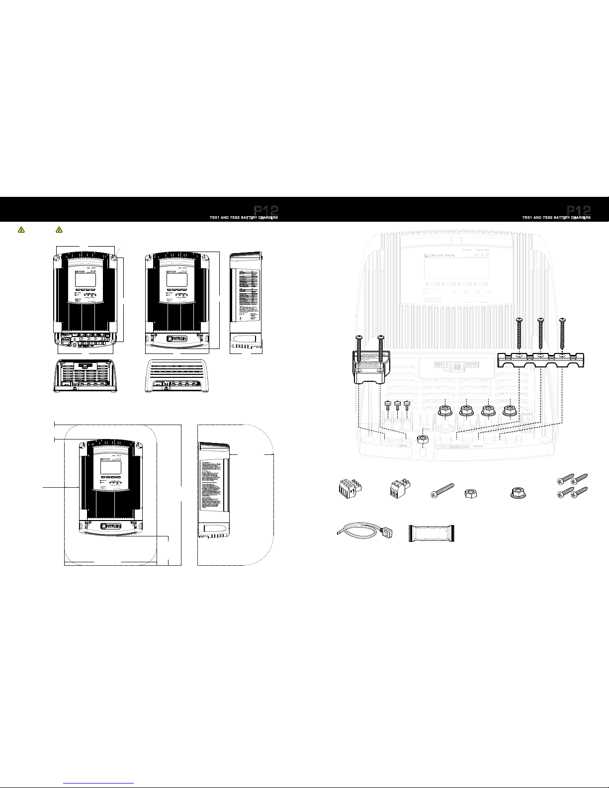
Product Dimensions
6
WARNING
For drip proof performance, and to meet ABYC requirements, the P12 Battery Charger must be mounted vertically as shown below.
Installation Clearances
P12
7531 AND 7532 BATTERY CHARGERS
Clearance for
#12, Ø1/4" M6
mounting hardware
7.80"
(198mm)
11.18"
(284mm)
7.40"
(188mm)
8.46"
(215mm)
4.30"
(109.1mm)
12.94"
(328.8mm)
14"-20
TOP
Recommended
side clearance
1.97
"
(50mm)
Recommended
overall envelope width
12.40
"
(315mm)
Recommended
clearance
for wire access
and inlet airflow.
3.94
"
(100.2mm)
Recommended
overall
envelope height
19.00
"
(480.6mm)
Recommended
top clearance
1.97
"
(50mm)
Recommended
clearance
for cooling fan exhaust.
do not block!
5.91
"
(150mm)
Included Components
77
Dielectric Grease
Mounting Screws
#12 x 1-1/4" sheet metal
screws (Use #3 Phillips
screwdriver)
Dielectric Grease
Used for Temperature Sensor and the
Optional Accessory P12 Remote Display Connections. View the
MSDS for the Dielectric Grease at bluesea.com/P12
Temperature Sensor
Flying lead, Battery Temp Sensor with
peel and stick adhesive
AC Strain Relief Insulating Cover Screws
M3 x 25mm pan-head machine screws (Use #1 Phillips screwdriver)
Recommended torque: 5–10 in-lb (0.6–1.1 Nm)
Pan-Head Machine Screws
M3.5 x 6mm
Recommended torque:
10–15 in-lb (1.0–1.8 Nm)
DC Strain Relief Clamp Screws
M3 x 25mm pan-head machine screws
Recommended torque:
5–10 in-lb (0.6–1.1 Nm)
DC Termination Nuts
1/4"-20 serrated flange hex-nuts
(Use 10mm socket wrench with extension)
Recommended torque: 70–80 in-lb (8–9 Nm)
DC Safety Ground Nut
M6 hex-nut
P12
7531 AND 7532 BATTERY CHARGERS
ACR Screw
Terminal Connector
Battery Temperature
Sensor Screw
Terminal Connector
DC Termination Nut
1/4"-20 serrated flange hex-nut
Accessory Pack Includes:
AC Strain Relief
and Insulating Cover
DC Strain
Relief Clamp
DC Strain Relief
Clamp Screw
M3 x 25mm pan-head
machine screw
P12 Battery Charger Hardware:
DC Safety Ground Nut
M6 hex-nut
Page 6

Specifications are subject to change. See bluesea.com/P12 for current information. Specifications are subject to change. See bluesea.com/P12 for current information.
Supplies Needed & Maintenance
8
1. AC Wire (see Table D page 5)
NOTE: Wire length must reach from the panel to the battery charger AC Connections with proper routing, support, drip loops, service loops, and termination.
NOTE: Yellow is preferred for negative however diagrams are drawn in black for visibility.
3. Fuse holders for connection to each battery. (see Table B page 5)
4. Fuses for fuse holders. (see Table B page 5)
5. Screwdrivers
• Flat blade screwdriver to release cover latch
• Phillips #2 – for AC termination and cover screws, and strain relief wire clamps
• Phillips #3 – for mounting screws
6. Socket wrench
• 7/16" socket with extension and ratchet handle or nut driver – for DC wire terminations
• 10mm socket – for DC safety ground termination
7. Ring terminals
• #6 (M3) ring or snap spade terminals sized for AC/Supply wire gauge (quantity 3)
• ¼" or M6 ring terminals sized for DC wire sizes (quantity 4)
8. Crimping tool or obtain wires that are pre-terminated
9. Appropriate heat shrink if pre-terminated wires were not acquired
2. DC Wire: Black or Yellow for negative and red for each positive. (see Table A page 5)
P12
7531 AND 7532 BATTERY CHARGERS
Installation & Operating Instructions
Installation Steps
1. Before beginning electrical installation, disconnect all positive and negative AC and DC power sources.
The P12 Battery Charger default startup mode is “User”. The battery charger will maintain a voltage but will not
charge batteries in this mode. After proper installation see page 11 to set up your battery type.
3. The yellow latches are locked/released by turning them ¼ turn with a flat blade screwdriver.
2. To reduce the risk of electrical shock, mount the battery charger vertically, in a dry and well ventilated location.
For drip proof installation, mount the battery charger in a vertical orientation.
NOTE: The charger should be located near the batteries to minimize wire length and its associated voltage drop to maximize charging efficiency.
If the batteries are not close together, place the charger near the largest bank of batteries.
NOTE: DC wiring should safely reach each battery positive and the battery negative common bus bar. Fuses should be installed at the battery positive
connections to prevent battery power from feeding back into a fault in the wiring, or in the battery charger. See Table A and B on page 5 for recommended values.
5. Route DC wires from each charger output to battery fuse holder, see Wiring Connections Diagram page 10.
4. Then remove the AC and DC wire termination strain relief clamps by unfastening the screws.
AC Connections Strain Relief DC Connections Strain Relief
Best practices and ABYC standards recommend that every positive wire on the boat, outside the engine starting circuit, must have circuit protection.
Please reference ABYC E-11 electrical standard for the most up to date recommendations.
9
DC
AC
WARNING
Be sure the area around the charger and batteries is well ventilated while the batteries are being charged. This unit is must be located in a dry, well
ventilated area, free from unsecured hardware. Do not mount the unit directly above or below batteries to prevent corrosive electrolyte or gases from
damaging the unit.
EXTERNAL CONNECTIONS TO CHARGER SHALL COMPLY WITH THE UNITED STATES COAST GUARD ELECTRICAL
REGULATIONS ( 33CFR183 SUB PART I)
P12
7531 AND 7532 BATTERY CHARGERS
MAINTENANCE INSTRUCTIONS
Periodic Maintenance Items. All other servicing must be performed by qualified service personnel!
• Verify P12 Battery Charger screen shows no fault condition and indicates normal operation
• Check fuses or circuit breakers to verify like new condition. Confirm no discoloration or corrosion exists and circuit breaker s will manually
trip and reset.
• Check for proper ventilation and that no debris has collected on the fan shroud or items have been improperly stored around
the P12 Battery Charger.
• Check battery terminal connections (both at batter y and at the P12 Battery Charger) for corrosion, clean and reconnect immediately
upon signs of corrosion.
• Per manufacturer’s instructions, check batteries for maintenance procedures.
• Check wire condition, overheating due to excessively long or too small conductors will result in hardening of the insulation or burn
marks at connections; if any of these signs exist, immediately replace with proper sized conductors.
DC Output Fuse Replacement
• Replacement of DC output fuses.
a. CAUTION!! Before replacing output fuses disconnect all sources of AC and all DC batteries and loads from the charger.
If you are not comfortable wor king on electrical systems, do not proceed. Seek help from a qualified marine electrician.
b. Remove terminations cover from the charger.
c. The fuses are located on the lower right of the charger adjacent to the negative battery stud.
d. Carefully remove both fuses by pulling the fuse straight out from the socket.
e. Replacement fuses must be ATC
®
type fuses with ignition protected rating (use of non-ignition protected rated fuses will render the entire
charger non-ignition protected, and therefore unsafe for use in an environment that requires an ignition protected rating).
Proper fuses are as follows: Model 7531, two 20A ATC
®
Fuses, Model 7532, two 25A ATC® Fuses.
Page 7

Specifications are subject to change. See bluesea.com/P12 for current information. Specifications are subject to change. See bluesea.com/P12 for current information.
Main Negative BusBar
Line
Neutral
Ground
AC Connections
#6 (M3) Ring Terminals
DC Connections
1/4" (M6) Ring Terminals
Battery 1
Fuse Fuse Fuse
Temperature
Sense
RJ11 Port
Remote
Display
RJ45 Port
External
Shutdown
Start Isolation
ACR2
RJ11 Port
Engine Start
Switch ACR1
RJ11 Port
Engine Start
Switch ACR2
RJ11 Port
Start Isolation
ACR1
RJ11 Port
DC Safety Ground
Battery 2
Battery 3
Installation Instructions (continued)
NOTE: If you have a Blue Sea Systems ACR with Start Isolation it is possible to take advantage of the P12 Battery Charger’s ability to integrate with it. The
P12 is designed to charge three electrically independent batteries or battery banks. The P12 has the unique capability to individually move each battery out of
Absorption charging stage. This ensures batteries near their full charge do not continue to receive high constant voltages necessary in the Absorption stage. This
is optimal treatment for long battery life. Charge Coordination integrates with the Blue Sea Systems family of Automatic Charging Relays (ACR) to force separation
of the battery bank while the P12 is operational, to allow the batteries to individually exit the absorption stage. (see pages 22–23)
6. Route the AC wires from the charger to the AC panel and terminate wires at the charger.
7. Make the AC source connections to the appropriate panel circuit breaker and leave in the “off” position. (see Table D page 5).
The connection to the supply mains is to be in accordance with the national wiring.
NOTE: Connect AC wiring, but do not energize the circuit until AC insulating cover is installed, DC is connected, and DC fuses are installed.
Wiring Connections
1. Attach the battery charger remote connection to the back of the P12 Battery Charger Remote using dielectric grease. Connect to the Remote Display/Com
port of the charger.
2. Connect the Automatic Charging Relay(s) (ACR) wire to the ACR Connection port(s)
Optional Installations see pages 22–23
10
8. Recommended Connection: Attach the battery temperature sensor wire to the largest battery bank. If all battery banks are the same size attach to bank with the most loads.
Blue Sea Systems recommends using a high quality dielectric grease for remote control and temperature sensor connections.
a. Attach the sensor in the center of the long side of the battery.
b. If multiple batteries are in a battery bank attach sensor
in the center between multiple batteries.
c. When external circumstances could create a significant
difference in temperature on one side of a battery versus
another, always attach temperature sensor on warmest side.
9. Install appropriate DC Fuses. (see Table B page 5)
10. Confirm all connections are accurately installed per
Wiring Connections Diagram.
11. Secure AC and DC strain relief covers and fasten down.
12. Secure the termination cover back over the connected wires
and latch the yellow tabs.
13. Restore AC power and turn on the AC supply circuit
breaker to the battery charger.
14. Perform the chargers setup procedure as outlined in
Initial Charger Setup page 11.
P12
7531 AND 7532 BATTERY CHARGERS
NOTE: The external
shutdown input is a ¼"
male quick connect.
Applying a voltage
between +5 and +32
volts DC (referenced to
the battery negative)
will place the charger
into standby mode.
When the voltage is
removed, the charger
will resume charging.
If the installation does
not require use of this
terminal, it may be
left unconnected.
Initial Charger Setup
11
During Initial Charger Setup, or after resetting to factory defaults, the following screens require user input to provide
functional battery charging.
1. Using the left or right arrow button, scroll to the desired language.
Press the Select button.
2. Once the desired language is highlighted, press OK button.
Press the Cancel button to go back.
3. Using the left or right arrow button, scroll to the desired battery type.
Press the Select button.
4. Once the desired battery type is highlighted, press the OK button.
Press the Cancel button to go back.
Note: If User mode is selected batteries will not charge until Absorb and Float voltages are altered.
See page 12-13 for Advanced Charger Setup.
5. Press the Back button twice to go to the Charger Summary screen.
Note: If battery type is unknown, see the label on the battery or contact a qualified marine electrician.
CAUTION
Selecting a battery type different from the connected batteries could limit the life of the
batteries and damage them.
Your charger is now operational.
For advanced setup options and information on Absorb and Float voltage, as well as absorb timers,
See page 12.
P12
7531 AND 7532 BATTERY CHARGERS
WARNING
If the supply cord is damaged, it must be replaced by a special cord or assembly available from the manufacturer or its service agent.
All-pole disconnection from the supply mains incorporated in the fixed wiring shall be provided in accordance with AS/NZS 3000.
Page 8

Specifications are subject to change. See bluesea.com/P12 for current information. Specifications are subject to change. See bluesea.com/P12 for current information.
Advanced Charger Setup
1. Press the Menu button.
2. Press the left
or right arrow buttons to scroll to the Fan Speed window
3. Press the Select button.
4. Press the up or down arrow buttons to select the desired speed.
a. High: The fan will spin up to its maximum speed. This is the recommended setting for optimal performance.
b. Low: The fan will spin up to a designated speed (below max). If there is a significant load on the charger, it may limit its maximum output current in
order to maintain a safe internal temperature.
c. Off: Forces the Fan to stay off. If there is significant load on the charger, it may limit its maximum output current to maintain a safe internal temperature.
6. Press the left
or right arrow buttons to scroll to the Max Output window.
7. Press the Select button.
8. Press the up or down arrow buttons to select the desired maximum output amperage. Low output may be selected to reduce load on the AC source.
AC current is approximately 15% of the DC current at 120V line voltage and 7% of the DC current at 240V line voltage.
9. Press the OK button once desired max amperage output is reached.
10. Press the left
or right arrow buttons to scroll to the Display window.
11. Press the Select button.
NOTE: The designated maximum amperage is the total available amperage to be supplied among all 3 outputs. Selecting an amperage less than the maximum
could result in under charging of batteries.
5. Press the OK button once desired speed is reached.
NOTE: Selecting High or Low will not necessarily turn the fan immediately on or increase the fan speed. In either of these settings the charger will only alter the fan
speed if the internal temperature rises enough to warrant fan circulation. The fan Low setting is for quiet mode.
12
12. Press the up or down arrow buttons to scroll to the desired display setting.
13. Press the Select button on the desired display setting to enable editing that setting.
a. Once selected, the amount of contrast and backlight can be adjusted using the left and right arrow buttons.
b. Press the OK button to enable desired setting.
14. Scroll to Backlight Timer and press the Select button.
a. Using the left and right arrow buttons you may adjust the length of seconds the backlight will remain on.
b. The backlight timer can be adjusted between 5 and 59 seconds. It may also be set permanently on or permanently off.
15. Press the OK button once desired backlight setting is reached.
16. Scroll to Language and press the Select button to adjust the display language.
17. Using the left or right arrow buttons scroll to the desired language.
18. Press the OK button.
Complete this setup to change language, limit fan noise, adjust backlight display and limit AC current draw.
P12
7531 AND 7532 BATTERY CHARGERS
19. Once desired display settings are enabled press Back.
20. Press the left or right arrow button to scroll to the Battery window.
21. Press the Select button.
Advanced Charger Setup (continued)
26. Press the Back button twice to return to the Charger Summar y screen.
27. Your P12 Battery Charger is now setup and fully operational.
22. While the cursor blinks on batter y type press the Select button.
23. Use the left
or right arrow buttons to scroll to desired battery type.
24. Press the OK button.
25. For optimal charging it is recommended to set absorption timers and End Absorb Amps. If Amp Hour Capacity is known, continue to page 14 for more information.
CAUTION
Selecting a battery type different from the connected batteries could limit the life of the batteries and damage them.
NOTE: to adjust Absorb and Float voltage “User” must be the selected battery type. The default Absorb voltages for each battery type can be seen in Table E above.
Warning: Incorrect Absorb and Float voltages could reduce the life of your batteries. Contact your battery manufacturer for recommended Absorb and Float voltages.
13
To reset the P12 Battery Charger to factory defaults, press and hold the two right buttons for ten seconds.
Press the OK button for five seconds to proceed with resetting to factory defaults or press the Cancel button to return to the previous screen.
Note: Resetting the P12 Battery Charger to factory defaults will erase previously saved data and settings.
Reset to Manufacturer Defaults
Type Absorb Volts Float Volts
FLA – Flooded Lead Acid 14.5V 13.5V
AGM – Absorbed Glass Mat 14.35V 13.3V
Gel – Gelled Electrolyte 14.1V 13.5V
TPPL – Thin Plate Pure Lead 14.7V
13.6V
¹
User Adjustable 12.5V Default 12.5V Default
¹ Taken from Odyssey Tech Notes, Northstar operation Manual
Table E: Default Voltages by Battery Type
Batteries should match in chemistry, although many AGM’s and flooded batteries are
compatible. Based on 25°C (77°F)
P12
7531 AND 7532 BATTERY CHARGERS
Page 9

Specifications are subject to change. See bluesea.com/P12 for current information. Specifications are subject to change. See bluesea.com/P12 for current information.
Absorption Parameters and Timers
14
CAUTION
The default Absorption Timer values are set to satisfy a majority of the battery configurations that exist. Unwarranted changes to Absorption timers could
result in damage to the batteries and reduced battery life. To optimize Absorption Timer based on specific configurations, please contact your
battery manufacturer for setting guidelines for your specific battery.
The Absorption stage is the charging stage in which a battery “fills” to max capacity. Absorption timers help define the amount of time a battery bank will
remain in the Absorption stage. Having a correct Absorption time is vital for optimum charging of a battery bank. Under Absorption can lead to a batter y
being consistently under-charged causing sulfate buildup. Over Absorption can dry out the electrolytes in a battery. Both of these conditions can lead to
reduced battery life.
There are three user selectable parameters that help define when a connected battery bank will be moved from Absorption to either Pre-Float, or Float.
Minimum Absorption Time: 1 hour default
The minimum amount of time a battery bank will be in Absorption. The battery charger will not move a battery from Absorb to Float unless the Minimum Absorption T ime is met.
Maximum Absorption Time: 4 hour default
The maximum amount of time a battery bank can remain in Absorption. While still maintaining its Absorption voltage, if a battery has been in Absorption for the maximum
designated time it will move into Float even if End Absorb Amps is elevated. This is commonly caused when active loads are present.
Recommended End Absorption Amps
End Absorb Amps will vary based on your specific system. To set the correct End Absorb Amps it is recommended
that you monitor the amperage entering your battery banks near the end of the absorption cycle. Constant loads
will affect this number, and should be incorporated into End Absorb Amps if present. However, in a typical system
(without constant loads) it is recommended that the End Absorb Amps be 1% of your battery banks amp-hour
capacity (see Table F).
End Absorption Amps
The maximum amount of current that a battery bank can receive while in Absorption and still change to Float. If a
load is active and drawing more than the designated End Absorption Amps, the battery bank will not leave Absorption
until the maximum Absorption time is met. For a battery bank to move from Absorption to Float before the maximum
Absorption time is met, the minimum Absorption time must be met, and the amperage output must be less than or
equal to the designated End Absorb Amps.
Flooded AGM Gel TPPL
Group
Size
Ah
1% End
Amps
Ah
1% End
Amps
Ah
1% End
Amps
Ah
1% End
Amps
24 75 0.8 79 0.8 73 0.7 76 0.8
27 90 0.9 92 0.9 86 0.9 91 0.9
31 105 1.1 105 1.1 97 1.0 102 1.0
4D 150 1.5 198 2.0 183 1.8 185 1.9
8D 200 2.0 245 2.5 225 2.3 228 2.3
Recommended Absorption Time
Minimum and Maximum Absorb Times can vary from installation to installation. It is recommended that Minimum and Maximum Absorption Times be based on the time it takes
a battery bank to reach End Absorb Amps. Read and understand the End Absorb Amps section above and set according to your system. After an accurate End Absorb Amperage
is set, monitor the minimum and maximum time it takes for each battery bank to reach their End Absorb Amps. The Minimum Absorb Time should be based on the minimum time
it takes a particular battery bank to reach End Absorb Amps. The Maximum Absorb Time should be an hour more than it takes a deeply discharged batter y bank to reach End
Absorb Amps. It is recommended to monitor charging while the battery banks are in different states of discharge to get the most accurate Minimum and Maximum Absorb Times.
Table F: Approximate End Absorb Amps
(1% of Ah Capacity)
Blue Sea Systems’ P12 Battery Chargers are designed and
tested to comply with California Energy Commission (CEC)
efficiency requirements and ship with these settings by default.
To disable this factory setting, select Charger Setup Menu,
select Battery and then press the down arrow and select
Set Absorb Timers. Then press the down arrow four times
to view General Charger Settings screen. Press Select and use
the left or right arrow buttons to toggle between ON
and OFF.
Complies with California Energy Commission (CEC)
efficiency requirements
Does not comply with California Energy Commission (CEC)
efficiency requirements
Energy Save Feature Control
P12
7531 AND 7532 BATTERY CHARGERS
Minimum Charge Temperature: The default is 0ºC
The lowest temperature of the sensor in which the charger will continue charging. If the temperature sensor measures below the minimum charge temperature, the charger will
enter standby mode, and cease to charge.
WARNING
Altering the default temperature parameters could cause serious property or personal damage. Contact your battery manufacturer to clarify the correct
temperature parameters for your specific batteries.
NOTE: Temperature parameters refer to the temperature measured at the temperature sensor, not the temperature of the charger. In this manual all temperatures
will be referenced in degrees in Celsius (°C). The user selectable range for battery temperature parameters is -20°C to 60°C. Ensure proper placement of battery
temperature sensor by referencing Step 8 on page 10
Maximum Charge Temperature: The default is 50ºC
The highest temperature of the sensor in which the charger will continue charging. If the temperature sensor measures above the maximum charge temperature, the charger will
enter standby mode, and cease to charge.
Battery Temperature Compensation (Tempco)
Battery temperature compensation is output voltage regulation based on battery temperature variances. Since batteries can see extreme temperature differences it is important
to regulate output voltage with temperature. A battery in a freezing environment should not be charged the same as a battery in a hot environment. The P12 Battery Charger
is set at a baseline of 25°C. Every degree variance from this baseline will result in a voltage variance on all outputs. For every degree above 25°C the charger will reduce all
output voltages by the value defined in Battery Tempco. For every degree below 25°C the charger will increase all output voltages by the value defined in Battery Tempco. For
example, with the default Battery Tempco set to -30mv/°C if the temperature sensor reads 26°C, then all output voltages will be reduced by .03V (30mv). If given the same
Battery Tempco and the temperature sensor reads 24°C, then all output voltages will be increased by .03V (30mv).
CAUTION
Charging batteries below 0°C can be potentially dangerous. Internal battery liquid can freeze and charging a frozen battery could cause serious proper ty or
personal damage. Contact your battery manufacturer for minimum safe charging temperature for your batteries before altering.
CAUTION
Charging batteries above 50°C can be potentially dangerous. Contact your battery manufacturer for the maximum safe charging temperature for your
batteries before altering.
CAUTION
Altering the battery temperature compensation value incorrectly can cause adverse effects on
your battery, by potentially reducing its life. Contact your battery manufacturer to find out the
specific temperature compensation parameters for your batteries.
15
Absorption Timer Counter
The P12 battery charger uses a counter to determine the amount of time a battery bank should remain in Absorb relative to the Maximum Absorb Time. The Absorb timers counter
can be seen in the System Status Screen and also referenced on page 19.
Absorption Parameters and Timers (continued)
Temperature Parameters
Available Timer Modes
When in Float or Standby, the timer will pause.
When in Pre-Float mode the timer for that channel will pause.
When in Bulk mode the remaining time will increase.
When in Absorption mode, the remaining time will decrease.
Once a battery bank’s Absorb timer is reduced to zero, then its output will be changed to Pre-Float. There are
other factors in a battery bank leaving the Absorption stage prior to the Absorb timer running out. Once all battery
banks leave Absorption, all outputs will enter the Float stage, or Rest stage if in Energy Save mode.
P12
7531 AND 7532 BATTERY CHARGERS
Page 10

Specifications are subject to change. See bluesea.com/P12 for current information. Specifications are subject to change. See bluesea.com/P12 for current information.
16
6. Press “I Accept” to continue.
7. Using the battery manufacturer’s parameters, input the correct equalization voltage, amperage, and time on the battery bank you would like to equalize.
You may only equalize one battery bank at a time.
Equalization
Definition of Equalization
Equalization is an increased voltage overcharge performed only on flooded lead acid batteries. Once a battery is fully charged equalization increases the voltage and forces
additional charge into the battery to combat negative chemical side effects that can occur in flooded batteries. It is done to compensate for stratification, a
condition where the acid concentration is uneven throughout the battery, and typically higher at the bottom. It is also done to remove sulfate crystals that build up
on the lead plates in flooded batteries.
Prior to Equalization
Contact the manufacturer of your flooded lead acid batteries to confirm the parameters of equalizing your specific batteries. Every battery manufacturer defines different
equalization parameters which are important to understand prior to equalization. All batteries must be fully charged and not under load from any device. The P12 Battery
Charger will not allow equalization to occur if batteries are discharged or powering any device.
Equalization Process
1. Confirm batteries are fully charged by verifying the charger is in Float mode with no active loads.
2. Turn off or disconnect all DC devices that are connected to the batteries. Disconnect the battery banks not being Equalized by removing the fuses at
the battery connection.
NOTE: Equalization parameters vary based on battery size. Confirm parameters for ever y battery connected to the charger before continuing.
WARNING
Equalization is a user selectable and potentially dangerous charging stage that should not be performed without sufficient knowledge. Personal or property
damage may occur if equalization is performed incorrectly. It is highly recommended that you seek professional guidance before performing equalization.
Equalization causes off gassing of harmful chemicals inside of the battery. Only perform equalization while the batteries are in a well-ventilated area away
from persons and animals.
CAUTION
Equalization may only be performed on flooded (wet) lead acid batteries. Serious personal or property damage may occur if equalization is
performed on any battery type other than flooded lead acid batteries.
NOTE: Equalization will only occur if the battery type is set to “Flooded Lead Acid” (FLA) or “User”. Do not proceed if you are using any other battery type.
See bluesea.com/P12 for details.
4. From any screen simultaneously press and hold the left and right most buttons for 5 seconds.
5. Read and understand the caution screen before proceeding.
3. Confirm use of flooded lead acid batteries.
NOTE: Equalization will not occur if steps 1 and 2 are not met.
P12
7531 AND 7532 BATTERY CHARGERS
17
8. To change battery, use the up down ar row buttons to scroll the cursor to the Bat1 window.
9. Press the Select button.
10. Using the left and right arrow buttons, scroll between the three different battery banks connected to the charger.
11. Confirm Equalization parameters for the batter y you wish to equalize.
12. Using the up down arrow buttons, scroll the cursor to the StartEQ window.
13. Press the Select button.
14. The charger will now begin to equalize and will display.
15. Monitor batteries and battery temperature throughout the Equalization process.
16. You may pause Equalization at any time by pressing the pause button.
17. If at any point during Equalization a DC load is applied to the battery being equalized, Equalization will stop.
18. You may stop Equalization at any time by pressing the stop
button.
Equalization (continued)
NOTE: If you receive the below warning screen confirm batteries are fully charged and all DC loads connected to the batteries are turned off. Once complete proceed
back to step 1 of the Equalization process.
NOTE: Pressing stop will return you to the Charger Summary screen.
19. Once the max Equalization voltage is reached the battery bank will begin to equalize for the designated Equalization time.
20. After the designated Equalization time is met Equalization will stop and the charger will return to the Charger Summar y Screen.
P12
7531 AND 7532 BATTERY CHARGERS
Page 11

Specifications are subject to change. See bluesea.com/P12 for current information. Specifications are subject to change. See bluesea.com/P12 for current information.
18
Charger Summary
The Charger Summary screen provides data of the battery’s status while the battery charger is operational.
Options:
- Press the History button to view previous charger performance
- Press the Menu button to view the Configuration Menu
How to Get Here:
From other screens in the charger, select the Back button.
Configuration Menu
The Configuration Menu has six user selections that allow modifications to Fan Speed, Charger Output,
Display, Battery Parameters, Temperature Limits, and Diagnostics.
Options:
- Scroll through the menu and select the desired option.
How to Get Here:
From the Charger Summary Screen, select the Menu button. From other screens, select the Back button.
Display Setup
The Display Setup allows the user to customize the display settings.
Options:
- Adjust Contrast
- Adjust Backlighting
- Set a Backlight Timer (length of time backlight will remain on)
- Select a language
How to Get Here:
From the Configuration Menu, select the Display button.
Charger Setup
The Charger Setup Menu is where the Battery Type and Absorb Timers are selected. Caution read
Absorption Parameters and Timers on page 14 before adjusting absorb timers.
Options:
- Select Battery Type or set Absorb Timers.
- If “User” is the selected battery type you may also adjust Absorb and Float voltage.
See page 14 for more information
How to Get Here:
From the Configuration Menu, select the Battery button.
Screen Summary
P12
7531 AND 7532 BATTERY CHARGERS
19
Temperature Parameters
The Temperature Parameters screen indicates the minimum and maximum operating temperature based on the
temperature sensor. Read the Temperature Parameters section on page 15 before making any adjustments.
Options:
- Select Units and temperature parameters to adjust.
How to Get Here:
From the Configuration Menu, select Temp Limits.
System Status
The System Status screen indicates which systems are functioning and the current firmware installed on the device.
Options:
- Select the Back button to go to the Configuration Menu.
- Select the Next button to view the status of the Absorb timers.
How to Get Here:
From the Configuration Menu, select Diagnostics
System Status Absorb Timers
The System Status Absorb Timers screen indicates the current Absorb time of each battery bank, as well as the
AC input voltage. The up down arrows indicate if time is being added or subtracted from the timer. If paused
the charger is in Float or Standby and the Absorb Timer will remain at its current time.
Read about Absorb Timers on page 14.
Options:
- Select the Back button to go to the System Status Screen.
- Select the Next button to view the charger Hour Meter Screen.
How to Get Here:
From the System Status Screen, select the Next button.
System Status Hour Meter
The System Status Hour Meter screen displays the overall time the charger has spent running at different
amperage levels.
Options:
- Select the Back button to go to the System Status Absorb Timers Screen.
How to Get Here:
From the System Status Absorb Timers Screen, select the Next button.
History
The History screen graphically displays the charging voltage and amperages per battery.
Options:
- Select the Back button to go to the Charger Summary Screen.
- Select individual batteries to view charging summary.
- Press and hold any Bat button for 3 seconds to switch from First 8 Hour view to Continuous.
How to Get Here:
From the Charger Summary Screen, select the History button.
Screen Summary (continued)
P12
7531 AND 7532 BATTERY CHARGERS
Page 12

Specifications are subject to change. See bluesea.com/P12 for current information. Specifications are subject to change. See bluesea.com/P12 for current information.
20
Alert Screens and Diagnostics
If at any time during the chargers life the red Alert light goes on, then the charger is not providing optimal performance.
The below Alerts encompass all of the possibilities for the charger to under perform. Alerts will be indicated by the red
Alert light as well as a pop-up screen explaining the reason.
Thermal Regulation
The P12 Battery Charger is equipped with an intelligent thermal regulation device for safe charging. If at any point
during charging a thermometer image begins to blink in the upper right hand corner of the screen, then the charger
has entered Thermal Regulation. This is not a failure, but a reduced current output state. While in this state the
internal temperature is being regulated by controlling the maximum output current. While in Thermal Regulation, the
charger will reduce output current to keep the charger at a safe operating temperature. The output can be regulated
all the way down to zero but is not likely. The most common correction for this state is to increase the fan speed
to High. If the fan speed is already set to High check for blockage around the fan vent that can be removed. If the
condition persists, it is advisable to reposition the battery charger in a cooler, more ventilated location.
Fan
The P12 Battery Charger is equipped with a variable speed fan. The fan is used to dissipate warm air produced from
high output currents during charging. The aluminum case of the P12 Battery Charger provides a large amount of heat
dissipation but for optimal performance the fan must be performing properly. If at any point the fan fails to perform
at its designated setting the Fan Alert Screen will appear. If this alert screen appears shut off AC power to the
battery charger as well as all battery connections. Determine if there is a blockage in or around the fan vent and
correct. Turn on AC power and check to see if the Fan Alert Screen appears. If the Fan Alert Screen does not appear
and the fan seems to be operating correctly, then continue to use the battery charger normally. If the Fan Alert
Screen appears contact Blue Sea Systems for fan replacement instructions.
Fan Fault
Check Fan for Blockage
Battery Temperature Sensor
As discussed in the Temperature Parameters section (page 15), there is an external battery temperature sensor
supplied with the unit. If at any point the temperature sensor records a temperature beyond the defined temperature
limits, the battery charger will display the Battery Temperature Alert Screen. In this situation all battery charging will
stop until the proper battery temperature is restored. Normal operation will not commence unless two degrees within
the temperature parameters. For example, if the maximum temperature parameter is set to 50°C and the
temperature sensor reads 51°C then the Battery Temperature Alert Screen will display. In this situation the battery
charger will not charge until the battery temperature sensor reads a maximum of 48°C. If no temperature sensor is
in use then battery temperature is not monitored and this alert will not be displayed.
CAUTION
Alteration of battery temperature parameters without sufficient knowledge is dangerous and can cause personal or property harm. If the batter y temperature sensor goes
outside a designated parameter, contact your battery manufacturer for further information on specific battery temperatures.
Battery Temperature
Out of Limits
Internal Temperature Sensor
The P12 Battery Charger is equipped with two internal temperature sensors. These sensors are unrelated to the
supplied external battery temperature sensor. If the Internal Temperature Sensor Alert Screen appears, then one
or more of the internal temperature sensors is not recording correct temperature data. Once in this state all battery
charging will stop. This form of temperature alert can not be corrected by the user. Contact Blue Sea Systems for
further information regarding internal temperature sensor alerts.
Internal Temp Below -20° C
Charger Will Restart When
Internal Temp Above -18° C
P12
7531 AND 7532 BATTERY CHARGERS
21
Alert Screens and Diagnostics (continued)
DC Output Voltage Too High
If at any point the charger detects a DC output voltage greater than 17.8V DC for five seconds, then the alert
screen on the right will appear. In this state the charger will cease to charge any batteries in order to prevent
damage. Shut off AC power for two minutes, and then restart. If the alert screen persists, shut off AC power and
contact Blue Sea Systems for further assistance.
DC Fuse
The DC output fuses have opened. The fuses are user serviceable. Please follow the procedure on Page 8 under the
Maintenance section for details on procedure and replacement fuse ratings.
WARNING
Before replacing fuses, check all wiring connections for proper polarity. A reverse polarity condition on the DC wiring
may be the cause of the fuse failure.
Fuse Failure
Contact Blue Sea Systems
360.738.8230
AC Input Voltage Too Low
If the AC input voltage drops below 85V AC, the alert screen on the right will appear. While in this state the
charger will cease to charge any batteries. Shut off power at the AC source for two minutes, and then restart. If the
alert screen persists, attempt to use a different AC power source, or contact an electrician to
diagnose the problem.
AC Input Voltage Too High
If the input voltage rises above 265V AC the alert screen on the right will appear. In this state the charger will
cease to charge any batteries. Shut off power at the AC source for two minutes and then restart. If the alert screen
persists, attempt to use a different AC power source, or contact an electrician to diagnose the problem.
AC Input Voltage too Low
Check for Proper AC Source
AC Input Voltage Too High
Check for Proper AC Source
DC Output Voltage Too High
Charger is off to prevent damage
Disconnect AC for 2 mins. then restart
EQ stopped-Max Current Limit
Make sure battery is charged
and all loads removed!
Equalization Overload
If at any point during equalization the total output current of the battery charger is greater than the defined
Maximum Equalization Current the Equalization Overload Alert Screen will appear. To correct, confirm batteries
are fully charged, and all loads are turned off prior to equalization. If mandatory 24-hour loads are present you may
adjust the Maximum Equalization Current accordingly. Once corrected, the equalization process must be restarted.
WARNING
Increasing the Maximum Equalization Current beyond your battery manufacturers recommendations is potentially
dangerous. Consult your battery manufacturer for proper equalization currents.
P12
7531 AND 7532 BATTERY CHARGERS
Page 13

Specifications are subject to change. See bluesea.com/P12 for current information. Specifications are subject to change. See bluesea.com/P12 for current information.
Optional Installation
SI-ACR and m-ACR Installation Instructions (PN 7610 and PN 7601) to Enable Start Isolation
1. Disconnect the DC Negative (Ground) wire going to the ACR.
2. If present, disconnect the Start Isolation wire connected to ACR.
3. Connect a wire from the ACR 1 port marked “SI” (Start Isolation) on the P12 Battery Charger to the Start Isolation terminal (SI) on the ACR.
4. Connect a wire from the ACR 1 terminal marked “ES” (Engine Start Switch) on the P12 Battery Charger to the terminal or wire running from the start key switch to
the starter solenoid. Make this connection through an in-line fuse of 1 to 10 Amps.
Integrate the P12 Battery Charger with Blue Sea Systems Automatic Charging Relays to take
advantage of Charge Coordination.
NOTE: If you have a Blue Sea Systems ACR with Start Isolation, it is possible to take advantage of your P12 charger’s ability to integrate in order to optimize
charging of your batteries.
Automatic Charging Relays (ACRs) combine battery banks when a charging voltage is present in order to share charge between battery banks. However, due to the P12 Battery
Charger’s ability to independently optimize charging for each battery bank it is favorable to isolate all battery banks by disengaging the ACR(s) ability to combine.
NOTE: The P12 Battery Charger can integrate with up to two Automatic Charging Relays (ACRs)
NOTE: This connection can be made at the start key switch or at the starter solenoid, but must be to the line that is +12V DC positive only when cranking. Connection
to a line that is positive while the engine is normally running will prevent the charging relay from working properly.
5. Re-connect DC Negative (Ground) wire on the ACR
6. If connecting two ACRs, repeat steps 1 through 5 using the second ACR, engine, and the P12 Battery Charger ports associated with ACR 2
22
P12
7531 AND 7532 BATTERY CHARGERS
Automatic
Charging
Relay
GROUND
START
ISOLATION
REMOTE LED
Automatic
Charging
Relay
GROUND
START
ISOLATION
REMOTE LED
ENGINE
START
SWITCH
ON
OFF
START
ENGINE
START
SWITCH
ON
OFF
START
FUSE FUSE
7520
BATTERY CHARGER LED REMOTE
Sold Separately
START
START
HOUSE
FUSEFUSE
FUSE
FUSE
DC GROUND
OPTIONAL CONNECTION
REMOTE DISPLAY
START ISOLATION (ACR 1) START ISOLATION (ACR 2)
ENGINE START SWITCH (ACR 1)
OPTIONAL CONNECTION
ENGINE START SWITCH (ACR 2)
Optional Installation (continued)
ML-ACR Installation Instructions (PN 7620 and PN 7622) to Enable Start Isolation*
1. Disconnect the black ground wire connected to the ML-ACR wire harness.
2. If present, disconnect all Start Isolation wires connected to the Brown, Green, and Orange wires in ML-ACR wire harness.
NOTE: This connection can be made at the start key switch or at the starter solenoid, but must be to the line that is +12V DC positive only when cranking. Connection to
a line that is positive while the engine is normally running will prevent the charging relay from working properly.
5. Re-connect the black DC Negative (Ground) wire in the ML-ACR wire harness
6. If connecting two ML-ACRs repeat steps 1 through 5 using the second ML-ACR, engine, and the P12 Battery Charger ports associated with ACR 2
4. Connect a wire from the ACR 1 terminal marked “ES” (Engine Start Switch) to the terminal or wire running from the start key switch to the starter solenoid.
NOTE: Connecting the “SI” (Start Isolation) wire to only one of the ML-ACR isolation wires will not properly integrate the P12 battery charger with your ML-ACR.
3. Connect a wire from the ACR 1 port marked “SI” (Start Isolation) on the P12 Battery Charger to both the Brown and Green wires in the ML-ACR wire harness.
23
* The ML-ACRs also support “Engine Isolation” which
keeps an ACR open if two engines are running
simultaneously. Operating in this mode while using
Charger Coordination requires a special installation.
See bluesea.com/P12 for details.
P12
7531 AND 7532 BATTERY CHARGERS
DC GROUND
ENGINE
START
SWITCH
ON
OFF
START
ENGINE START
SWITCH
A B
ML-Series
Automatic
Charging
Relay
A B
START ISOLATION #2 (GREEN)
ENGINE ISOLATION #3 (ORANGE)
START ISOLATION #1 (BROWN)
GROUND (BLACK)
ML-Series
Automatic
Charging
Relay
ISOLATION #2 (GREEN)
ISOLATION #3 (ORANGE)
ISOLATION #1 (BROWN)
GROUND (BLACK)
7520
BATTERY CHARGER LED REMOTE
Sold Separately
OPTIONAL CONNECTION
START
HOUSE
START
ON
OFF
START
REMOTE DISPLAY
START ISOLATION (ACR 1)
START ISOLATION (ACR 2)
ENGINE START SWITCH (ACR 1)
OPTIONAL CONNECTION
ENGINE START SWITCH (ACR 2)
Page 14

Specifications are subject to change. See bluesea.com/P12 for current information. Specifications are subject to change. See bluesea.com/P12 for current information.
24
Warranty and Contact Information
7520 1521 7610 7622 7700 5502 7720
Register your P12 Battery Charger at bluesea.com/warranty
Blue Sea Systems stands behind its products for as long as you own them. Blue Sea Systems will replace or issue a credit for any of its products found
to be defective in materials or manufacture. P12 Battery Chargers and P12 Remote Displays are warranted for a period of five years from the date of first
purchase. No compensation will be allowed for products not returned to Blue Sea Systems for analysis, nor will compensation be made for labor required
to replace any defective product. Please contact Customer Service for an RMA number prior to shipping any product back to Blue Sea Systems. Blue Sea
Systems cannot accept liability for damage due to the use of the P12 Battery Charger.
“Date of first purchase” means:
1. The date on which the product was purchased by the first retail customer
2. The date on which the first retail customer purchases a vessel on which the product was installed
Blue Sea Systems will (at its sole discretion) repair or replace any product which is:
1. Proven to be defective in materials or workmanship
2. Returned to Blue Sea Systems (or its agent) during the war ranty period in accordance with this warranty
The replacement battery charger may be new or refurbished in as-new condition. Such repair or replacement will be the sole remedy by Blue Sea Systems
under this warranty. Any repaired or replacement product will be warranted in accordance with this warranty for the unexpired balance of the warranty period
on the original product.
Blue Sea Systems Technical Support
Monday through Friday
8:00am - 5:00pm (PST)
1-800-222-7617
techsupport@bluesea.com
Related Products
P12 Battery Charger LED Remote 7520
360 Panel - P12 Battery Charger LED Remote 1521
SI Series Automatic Charging Relay 7610
ML Series Automatic Charging Relay 7622
ML Series Remote Battery Switch 7700
Class-T Fuse Block 5502
Safety Fuse Block (MIDI®/AMI®) 7720
Twin Engine
3 Battery Bank
360 Panel System
RBS
RBS
Starter
Alternator
Starter
PowerBar
(System Ground)
Alternator
House
Start 1 Start 2
RBS
ACRs
LEGEND
DC Positive
AC Line
System Ground
Control
Class-T
Fuse Block
10
11 12 13 13 12
15
16
5
6
7
8
9
3
4
2
1
P12 Battery Charger
14
Engine 1
Engine 2
AMI®/MIDI® Fuse Block
15
AMI®/MIDI® Fuse Block
15
System Functions:
1 AC Amperage, Voltage, and Frequency measurement with alarms
2 AC ELCI Ground Fault Protection
3 AC Source Selection
4 AC Branch Circuit Protection and Switching
5 DC Battery Charger Remote Monitoring and Control
6 DC Amperage and Voltage measurement with alarms
7 DC Branch Circuit Protection and Switching
8 DC Remote Battery Isolation Switching
9 DC Remote Automatic Charging Relay (ACR) Switching
10 3 Bank Battery Charging
11 House Battery Isolation
12 Engine Battery Isolation
13 Charge Distribution Engine 1 – Engine 2 – House
14 Charge Coordination – ACR’s Disabled if Battery Charger Active
15 DC Main Circuit Protection
16 System Ground
P12 Charge Management System
25
Page 15

425 Sequoia Drive
Bellingham, WA 98226 USA
p 360.738.8230
p 800.222.7617 USA and Canada Customer Service
conductor@bluesea.com
www.bluesea.com
980025140 Rev. 003
 Loading...