

Blue Sea Systems 1841 Instructions Manual
M2 OLED Temperature Monitor Instructions
PN 1841
Installation Checklist
• Check for components included
• Read Warning and Cautions
• Read page 3 for mounting instructions
• Read System Overview, Mounting Considerations, Detailed Wiring,
and Sensing Description
• Follow Initial System Setup instructions
• Congure Displays
• Congure Alarms
• Congure Relays
Specications
Display Size 55mm x 28mm
Power Supply 7V–70V DC
Power Consumption 0.3W–1.0W*
Sensors Blue Sea Systems PN (1821)
Sensor Range -40°F – 250°F (-40°C –120°C)
Sensor Resolution 1%
Temp Alarms 80dB
External Relay 0.5A DC
* Variable with voltage, display intensity, and sleep mode
Regulatory
Monitor face is IP66 – protected against powerful water jets
when installed according to instructions
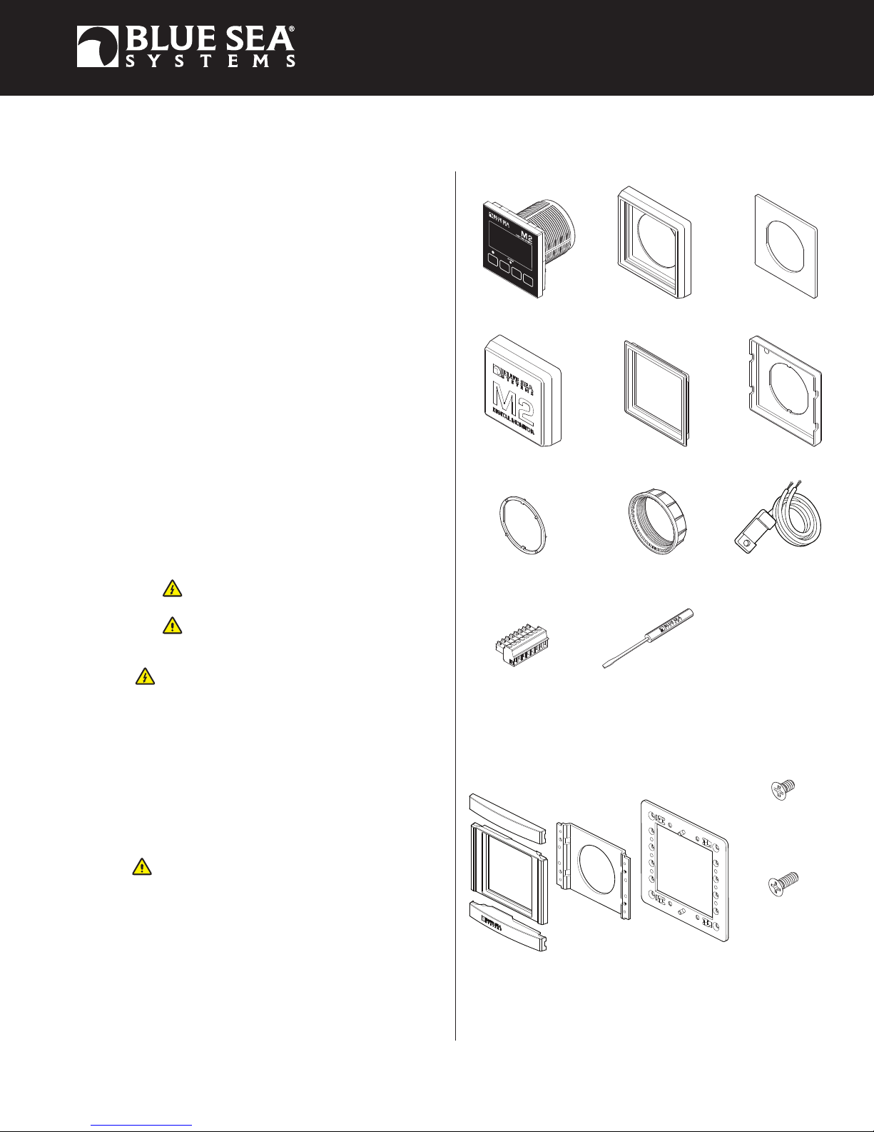
Components Included
M2 Head Unit Surface Mount Gasket
Surface Mount Cover
Surface Mount Bezel
and Seal
Flat Mount Bezel
Flat Mount Clamp
Warning and Caution Symbols
WARNING: The symbol refers to possible injury to the user or
signicant damage to the meter if the user does not follow the procedures.
CAUTION: The symbol refers to restrictions and rules with regard
to preventing damage to the meter.
WARNING
• If you are not knowledgeable about electrical systems, have an
electrical professional install this unit. The diagrams in these
instructions pertain to the installation of M2 Digital Meters and not
to the overall wiring of the vessel.
• If an inverter is installed on the vessel, its power leads must be
disconnected at the battery before the meter is installed.
• If an AC generator is installed on the vessel, it must be stopped
and rendered inoperable before the meter is installed.
• Verify that no other DC or AC sources are connected to the vessel’s
wiring before installing the meter.
CAUTION
• The back of the unit is not waterproof. Do not install where the back
of the meter is exposed to water.
Mounting Ring
Connector
Mounting Nut
Screwdriver
Retail Package Only
Temperature Sensors
360 Panel Mounting Kit (PN 1525 sold separately)
Bezel
Mount
Header
Footer
Carrier
Mount
Panel
Frame
#6-32 x 1/4"
Machine Screws
#6-32 x 3/8"
Machine Screws
4x 1821
Flat Head
(4X)
Flat Head
(4X)
1
Installation
1. Make all connections to the meter’s terminal block before connecting the terminal block to the unit.
Keep hands away from the terminal block when applying power to the meter.
2. As the nal DC connection, insert a fuse into the in-line fuse holder on the wire to the positive (+) battery terminal.
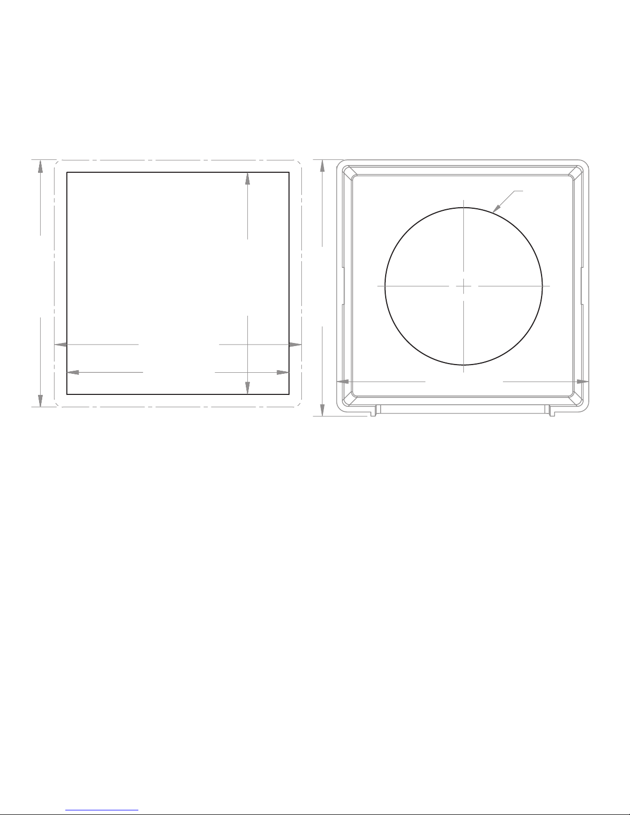
Mounting Templates
Flat Mount
3.00" (76.2mm)
3.34" (84.8mm)
3.46" (87.9mm)
3.34" (84.8mm)
3.00" (76.2mm)
Surface Mount
Ø2.125"
(54mm)
3.40" (86.5mm)
Mounting Considerations
M2 Digital Meters have three mounting methods: surface mount, at panel mount, and 360 panel mount. When surface mounted per instructions the
unit face is waterproof to IP66. Flat panel and 360 panel mounting systems are not waterproof. The unit should not be at panel or 360 panel mounted
if used in an exposed location. For all mountings, the back of the unit is not waterproof and must be kept dry.
2
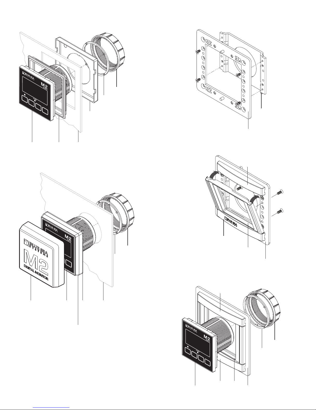
Flat Mount
M2
Head
Unit
Flat
Mount
Bezel
Clamp
Mounting
Substrate
360 Panel Mount PN 1525
STEP 1
Use 1/4"
Mounting
Screws
Mounting
Ring and Nut
360 Panel
Mount
Carrier
Panel
Frame
Surface Mount
Surface
Mount
Cover
M2
Head
Unit
Surface
Mount
Gasket
Mounting
Ring and Nut
Mounting
Substrate
STEP 2
Snap header
and footer
into mounting
clips and post.
Snap the
mounting bezel
into place
with the flat
edge up.
STEP 3
Header
Footer
Bezel
Panel
Frame
Header
NOTE: During
installation use cover
to align the bezel
and gasket
Surface
Mount
Bezel
and Seal
M2
Head
Unit
Mounting
Ring and Nut
Panel
BezelFooter
Frame
3
Temperature Functions (1841)
Monitor up to four temperatures. Provides High/Low level alarms for each channel.
Connections
IMPORTANT! The Sensing Description section of this manual gives important details to the location of sensors in the AC and DC electrical
systems of the boat. Improper location and conguration of sensors can result in erroneous readings and possible damage to components.
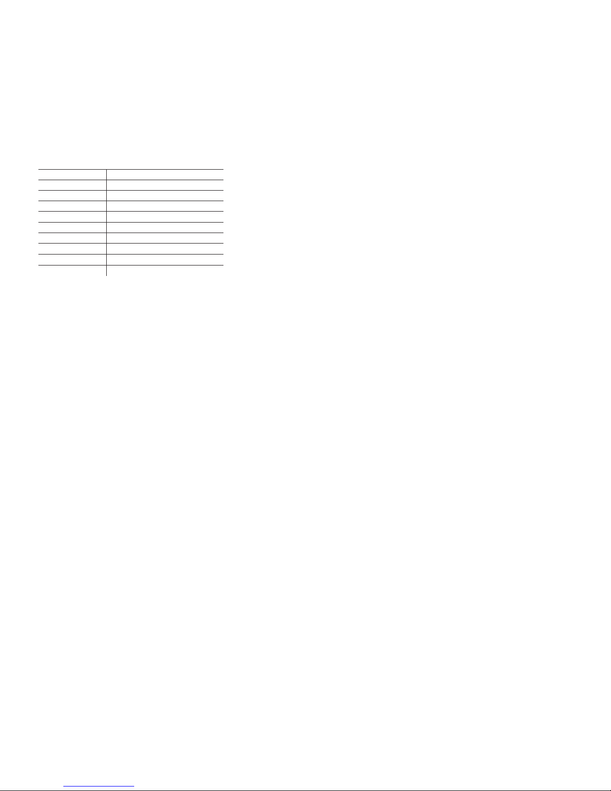
Pin-out Table
1841 Connector Pin Assignment Table
8 Pin Connector*
1 Required Connection
2 Required Connection
3
4
5
6
7
8
USB Micro USB Port
*The 8 pin low voltage connector supports wire sizes from 16-26 AWG
Function
DC Negative
DC Supply
Relay DC Out to Load
Relay DC +
Temperature 1
Temperature 2
Temperature 3
Temperature 4
Meter Power Supply Connections
All meters must have pins 1 (DC Negative) and 2 (DC Supply) connected. These pins are used to provide power to the meter. Connect pin 1 to ground
and pin 2 to a 12V to 48V power source.
Temperature Connections
Use Blue Sea Systems Temperature Sensor 1821
Only use Blue Sea Systems temperature sensor PN 1821. Other temperature sensors may not give the correct temperature result.
The negative lead of all the temperature sensors should terminate as close as possible to pin 1. For a simple and clean installation, use
Blue Sea Systems PN 2304 as a small common bus bar for all of the meters DC negative connection. There should be one connection between pin 1 of
the meter and the bus bar using 18 AWG wire. This connection should be as short as possible to minimize temperature reading errors.
4
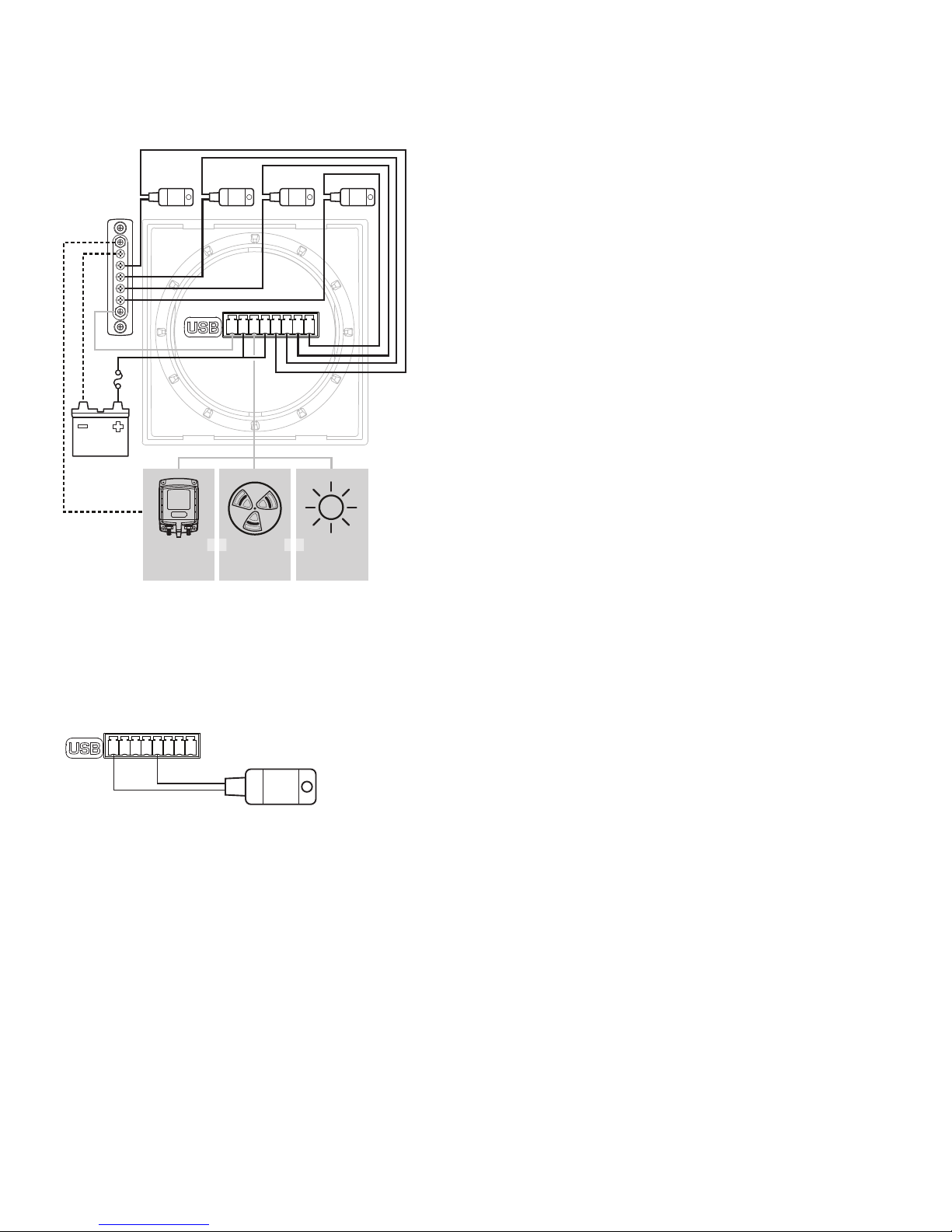
Detailed Wiring
1841 Temperature Monitor
Temp 1 Temp 2 Temp 3 Temp 4
12345678
Battery
Relay
(7713 12V)
(7717 24V)
Alarm (1070)
OROR
LED
(8033 Amber)
(8171 Red)
(8172 Green)
Note: The negative feed of all of the temperature sensors should terminate
as close as possible to pin 1. Use Blue Sea Systems’ PN 2304 Mini Bus
with a short 18 AWG guage wire from pin 1 to the Mini Bus.
Temperature Sensor Connections 1821
12345678
1821 Temperature Sensor
Temperature 1 Example
5
 Loading...