

Page 1
AC M2 OLED Meter Instructions
PN 1836/ PN 1837 / PN 1838
Installation Checklist
• Check for components included
• Read Warning and Cautions
• Read QuickStart Installation Guide for mounting instructions
• Read System Overview, Mounting Considerations, Detailed Wiring,
and Sensing Description
• Read QuickStart Installation Guide for installation notes
• Follow Initial System Setup instructions
• Congure Displays
• Congure Alarms
• Congure Relays
Display Size 55mm x 28mm
Power Supply 7V–70V DC
Power Consumption 0.3W–1.0W*
* Variable with voltage, display intensity, and sleep mode
Regulatory
Monitor face is IP66 – protected against powerful water jets
when installed according to instructions
1836 Specications
Current
Range 0A–150A (300A optional)†
Resolution (100 to 150) 1A
Resolution (0.0 to 99.9) 0.1A
Current Transformer Included 1 × PN 8256 (150A /50mA)
Alarm / Relay Activation High and Low Current
1837 Specications
Voltage
Range 50V–250V AC (RMS)
Resolution 1V AC
Alarm / Relay Activation High and Low Voltage
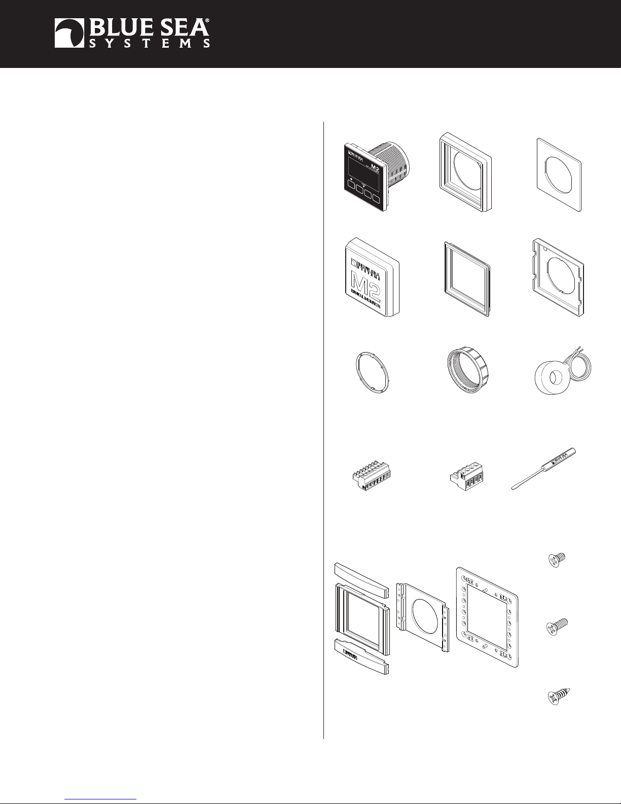
Components Included
M2 Head Unit Surface Mount Gasket
Surface Mount Cover
Mounting Ring
Surface Mount Bezel
and Seal
Flat Mount Bezel
Mounting Nut
Flat Mount Clamp
AC Current Transformer
8256 (1X)
1836 and 1838 Only
1838 Specications
Voltage
Range 50V–250V AC (RMS)
Resolution 1V AC
Current
Range 0A–150A (300A optional)†
Resolution (100 to 150) 1A
Resolution (0.0 to 99.9) 0.1A
Current Transformer Included 1 × PN 8256 (150A /50mA)
Alarm / Relay Activation High and Low Voltage, Current,
and Frequency
Frequency
Range 40Hz–90Hz
Resolution 1 Hz
Power
Range 0W–45kW
Resolution (0W–9990W) 10W
Resolution (10kW–45kW) 0.1kW
† Will achieve 300A with an optional current transformer PN 1829
Connector
Connector
1837 and 1838 Only
Screwdriver
Retail Package Only
360 Panel Mounting Kit (PN 1525 sold separately)
Bezel
Mount
Header
Footer
Carrier
Mount
Panel
Frame
#6-32 x 1/4"
Machine Screws
#6-32 x 3/8"
Machine Screws
Flat Head Sheet
Metal Screws
Flat Head
(4X)
Flat Head
(4X)
#8 x 1/2"
(4X)
1
Page 2
Warning And Caution Symbols
WARNING: The symbol refers to possible injury to the user or signicant damage to the meter if the user does not follow the procedures.
CAUTION: The symbol refers to restrictions and rules with regard to preventing damage to the meter.
WARNING
• Verify that all AC sources are disconnected before connecting or disconnecting the current transformer. Failure to do so will generate lethal voltages
on the current transformer.
• If you are not knowledgeable about electrical systems, have an electrical professional install this unit. The diagrams in these instructions pertain to
the installation of M2 Digital Meters and not to the overall wiring of the vessel.
• If an inverter is installed on the vessel, its power leads must be disconnected at the battery before the meter is installed.
• If an AC generator is installed on the vessel, it must be stopped and rendered inoperable before the meter is installed.
• Verify that no other DC or AC sources are connected to the vessel’s wiring before installing the meter.
• If the meter must be removed, connect the current transformer leads together before restoring power to the AC system. (P/Ns 1836 & 1838 Only)
CAUTION
• The back of the unit is not waterproof. Do not install where the back of the meter is exposed to water.
Installation
1. Make all connections to the meter’s terminal block before connecting the terminal block to the unit.
Keep hands away from the terminal block when applying power to the meter.
2. As the nal DC connection, insert a fuse into the in-line fuse holder on the wire to the positive (+) battery terminal.
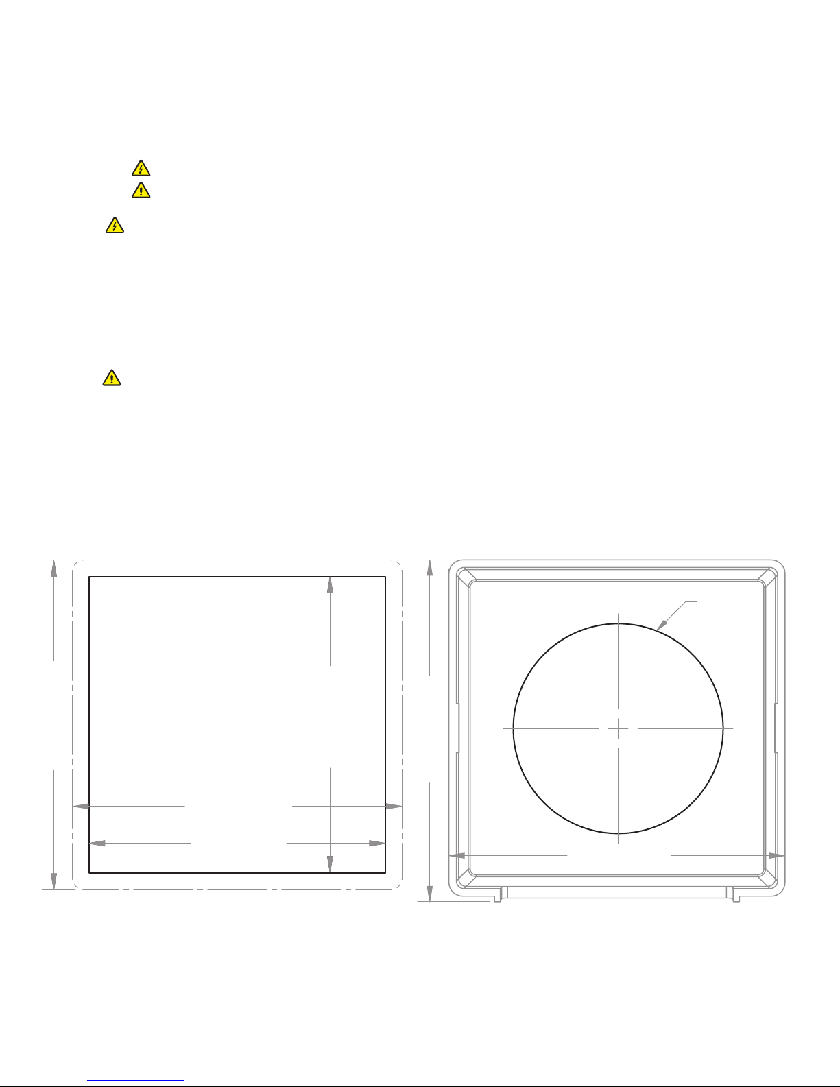
Mounting Templates
Flat Mount
3.34" (84.8mm)
3.34" (84.8mm)
3.00" (76.2mm)
3.00" (76.2mm)
3.46" (87.9mm)
Surface Mount
Ø2.125"
(54mm)
3.40" (86.5mm)
2
Page 3
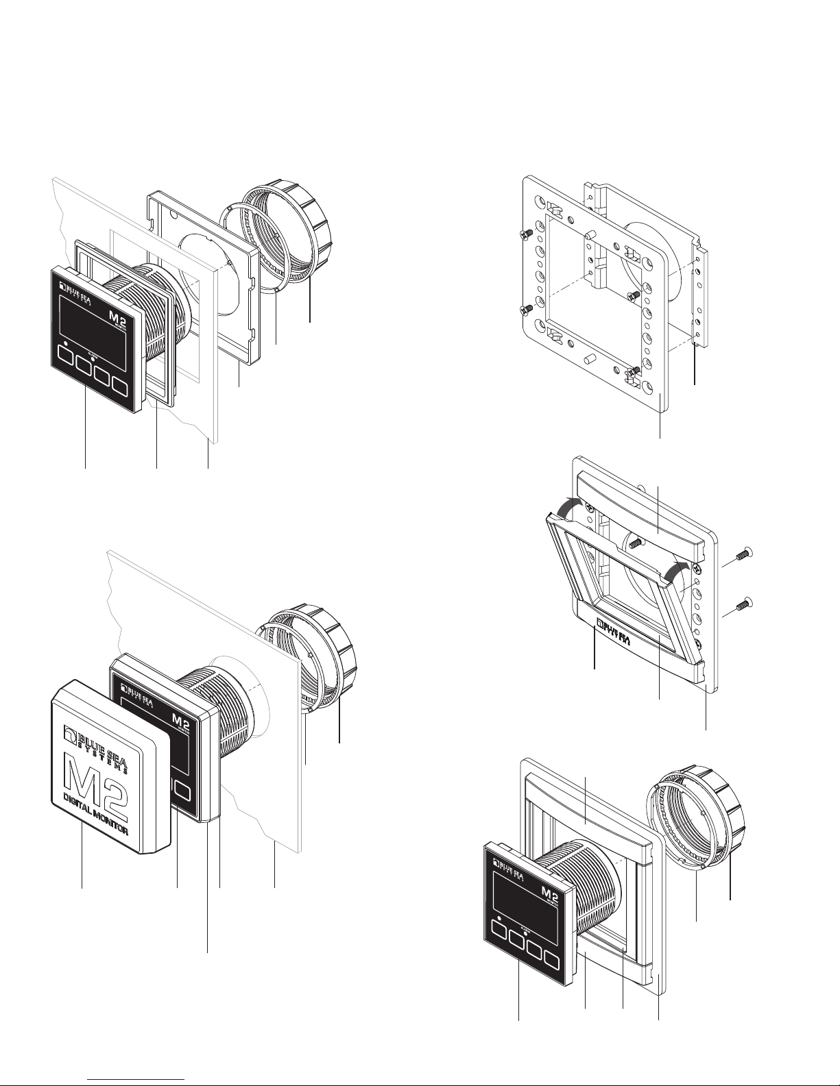
Mounting Considerations
M2 Digital Meters have three mounting methods: Surface mount, Flat panel mount, and 360 panel mount. When surface mounted per instructions the
unit face is waterproof to IP66. Flat panel and 360 mounting systems are not waterproof. The unit should not be at panel or 360 mounted if used in an
exposed location. For all mountings, the back of the unit is not waterproof and must be kept dry.
Flat Mount
M2
Head
Unit
Surface Mount
Flat
Mount
Bezel
Clamp
Mounting
Substrate
Mounting
Ring and Nut
360 Panel Mount PN 1525
STEP 1
Use 1/4"
Mounting
Screws
STEP 2
Snap header
and footer
into mounting
clips and post.
Snap the
mounting bezel
into place
with the flat
edge up.
360 Panel
Mount
Carrier
Panel
Frame
Header
Surface
Mount
Cover
NOTE: During
installation use cover
to align the bezel
and gasket
M2
Head
Unit
Surface
Mount
Gasket
Surface
Mount
Bezel
and Seal
Mounting
Ring and Nut
Mounting
Substrate
STEP 3
M2
Head
Unit
Footer
Header
Bezel
Panel
Frame
Mounting
Ring and Nut
Panel
BezelFooter
Frame
3
Page 4

AC Functions (1836, 1837, 1838)
1836 AC Ammeter measures the current draw of up to two sources or legs.
1837 AC Voltmeter measures the voltages of up to two sources or legs.
1838 AC Multimeter measures the voltages and current draws of up to two sources or legs.
Connections
IMPORTANT! The Sensing Description section of this manual gives important details to the location of sensors in the AC and DC
electrical systems of the boat. Improper location and configuration of sensors can result in erroneous readings and possible damage to
components.
Pinout Tables
1836 Connector Pin Assignment Table
8 Pin Connector*
1 Required Connection
Required Connection
2
3
4
5
6
7
8
USB
*The 8 pin low voltage connector supports wire sizes from 16-26 AWG
Function
DC Negative
DC Positive
Relay DC Out to Load
Relay DC +
AC 1 Current Transformer –
AC 1 Current Transformer +
AC 2 Current Transformer –
AC 2 Current Transformer +
Micro USB Port
1837 Connector Pin Assignment Table
4 Pin Connector*
1 AC Voltage 1 - HOT
2
3
4
8 Pin Connector**
1
Required Connection
Required Connection
2
3
4
5
6
7
8
USB Micro USB Port
*The 4 pin high voltage connector supports wire sizes from 12-24 AWG
**The 8 pin low voltage connector supports wire sizes from 16-26 AWG
Function
AC Voltage 1 - NEUTRAL
AC Voltage 2 - NEUTRAL
AC Voltage 2 - HOT
Function
DC Negative
DC Positive
Relay DC Out to Load
Relay DC +
No Connection
No Connection
No Connection
No Connection
1838 Connector Pin Assignment Table
4 Pin Connector*
1 AC Voltage 1 - HOT
2
3
4
8 Pin Connector**
1
Required Connection
2
Required Connection
3
4
5
6
7
8
USB
*The 4 pin high voltage connector supports wire sizes from 12-24 AWG
**The 8 pin low voltage connector supports wire sizes from 16-26 AWG
Function
AC Voltage 1 - NEUTRAL
AC Voltage 2 - NEUTRAL
AC Voltage 2 - HOT
Function
DC Negative
DC Positive
Relay DC Out to Load
Relay DC +
AC 1 Current Transformer –
AC 1 Current Transformer +
AC 2 Current Transformer –
AC 2 Current Transformer +
Micro USB Port
Meter Power Supply Connections
All meters must have pins 1 (DC Neg.) and 2 (DC Pos.) connected. These pins are used to provide power to the meter. Connect pin 1 to ground and pin
2 to a 12V to 48V power source. Note on some DC meters pin 2 is also used to monitor additional voltages.
AC Connections (1836, 1837, 1838)
AC Current
In most cases, the AC Current Transformer should be located on the main AC line wire before any other devices.
The Current Transformer does not indicate polarity. The leads should be twisted to reduce the effects of interference from other electrical circuits.
AC Voltage
The AC supply HOT ( Line, or “Ungrounded Conductor”) connection should be protected with a fast acting fuse of 0.25A to 0.5A to protect against shorts.
4
Page 5
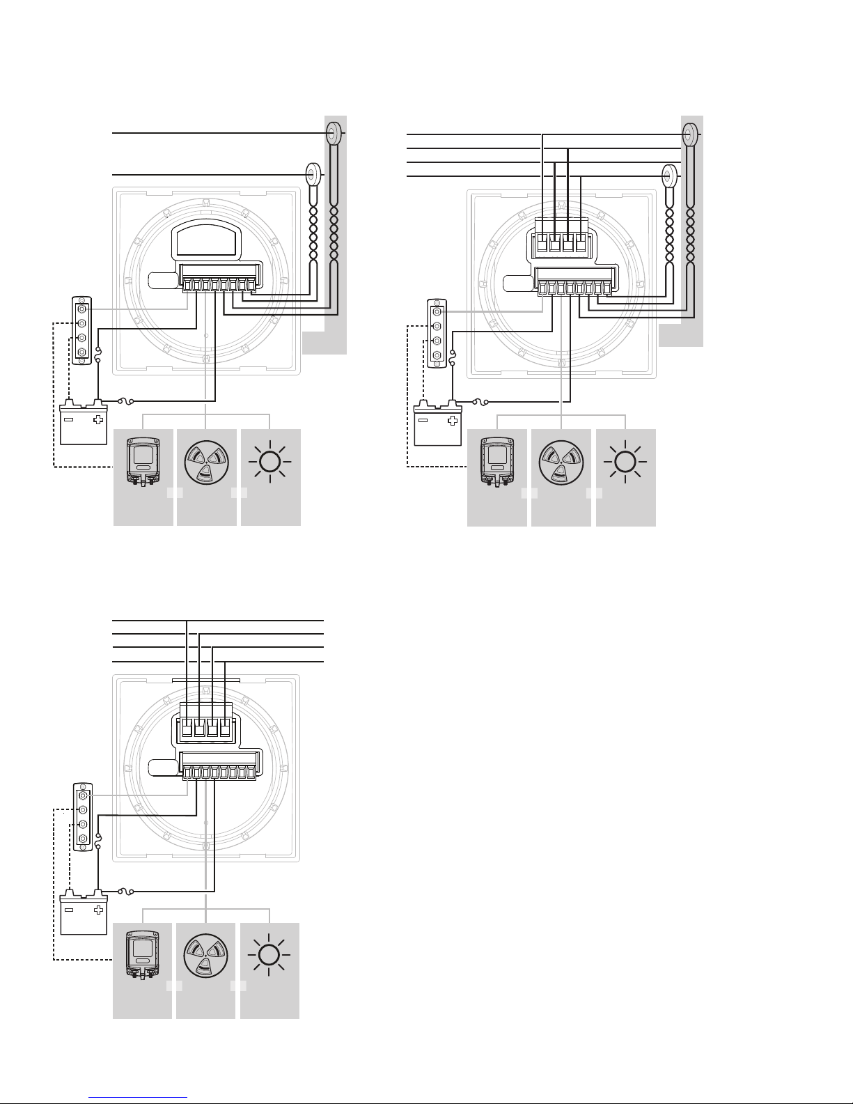
Detailed Wiring
1836 AC Ammeter
To loads
To loads
Relay
7713, 12V
7717, 24V
AC
1 H
AC
2 H
12345678
Alarm
OROR
1070
From source
LED 12/24V
8033, Amber
8171, Red
8172, Green
Optional
Transformer
1838 AC Multimeter (North American 120V / European 230V)
OROR
From Supply
LED 12/24V
8033, Amber
8171, Red
8172, Green
Optional
Transformer
To loads
1 H
AC
AC
2 N
AC
1 N
AC
2 H
Relay
7713, 12V
7717, 24V
1 2 3 4
12345678
Alarm
1070
1837 AC Voltmeter
To loads
Relay
7713, 12V
7717, 24V
AC
1 H
AC
1 N
AC
2 N
AC
2 H
1 2 3 4
V
1 H V1 N V2 N V2 H
12345678
Alarm
1070
OROR
LED 12/24V
8033, Amber
8171, Red
8172, Green
From Source
5
Page 6

Detailed Wiring continued
1838 AC Multimeter (North American Split Phase 120V / 240V)
To monitor a split/phase system, place the AC 1 & 2 Voltage Hot (‘LINE”, or “Ungrounded Conductors”) and Neutral (“Grounded Conductor”) connections
on the LOAD side of the transfer switch as indicated in the diagram.
NOTE: AC 1 Voltage Neutral and AC 2 Voltage Neutral are tied together.
To loads
1 H
AC
AC
N
AC
2 H
Relay
7713, 12V
7717, 24V
1 2 3 4
12345678
Alarm
OROR
1070
From Supply
LED 12/24V
8033, Amber
8171, Red
8172, Green
Optional
Transformer
M2 Relay Connections
M2 Meters contains an internal MOSFET relay that can drive external DC loads up to 0.5A. The input is protected with a thermally activated
auto-resetting fuse that will protect against shorts. In addition, an inline fuse rated at 5A should be used to protect against shorts. In typical applications,
a power source is connected to the Relay+ pin and a load is connected to the Relay Out to Load connection. In the P/Ns 1830, 1833, and 1834 meters,
the Relay+ connection can also be used to monitor a voltage.
4
3
6
Relay Supply
Pin 4 voltage connections are only
required if the relay is used.
Optically isolated relay control
500mA DC Maximum current
Page 7

External LED
An external LED such PN 8171 can be connected to the Relay Output terminal. If the system is going to operate at more than 24V nominal, an additional
4K Ohms of resistance should be placed in-line with the LED.
LED
Supply
8 to 70V
12345678
Red Wire
LED,
12V/24V
8033, Amber
8171, Red
8172, Green
Yellow Wire
External Alarm (1070 Floyd Bell Turbo)
The Relay+ terminal can support an external audible alarm. Such as the Floyd Bell Turbo Alarm (PN 1070).
External
Alarm
Supply
5 to 30V DC
12345678
+ Red
- Silver
1070
7
Page 8

External Relay
If you need to switch more than 0.5 A, you can use an external relay such as PN 7713, 12V or PN 7717, 24V Remote Battery Switch. Connect the
Relay+ terminal to the red control wire. Activating the internal relay will also activate PN 7713.
NOTE: 9012, 7700, 7701, 7702, & 7703 Remote Battery Switches are not compatible with the internal relay.
12V or
24V DC
12345678
NOTE: For optional SPST
switch connections
Wire connections are the same
as the SPDT, ON-ON except
the Ground is omitted.
CONTROL (red)
A
B
orange
green
brown
LED OUTPUT (yellow)
GROUND (black)
No Connection
Refridgerator
8
Page 9

Getting Started
Example Screens From PN 1838 AC Multimeter
When an M2 Meter is initially powered up, it will display the Blue Sea Systems Logo,its serial number and its Software revision.
After a couple of seconds, the unit will display a high-level System Summary screen.
Pressing any button will display a temporary pop-up menu. Select an option by pressing the button beneath it. The pop-up menu will disappear after the
rst button is pressed.
The menu system is a two dimensional matrix. Pressing the the UP ↑ or DOWN ↓ arrow buttons will transition the display between the System
Summary screen which displays summary information for each of the “voltage” or “current” channels.
Press the Next button to display more detailed information about an input channel or to show a single parameter, such as “voltage” in the display
(see example below).
Press the Menu button to bring up a shortcut menu to for additional summary screens as well as to access the Setup menus. Press the UP ↑
and DOWN ↓ arrow buttons to move the cursor over the options and press the Select button to see a selected display.
To return to the previous display, press the Back button.
9
Page 10

Conguring the Meter
Meter settings can be congured from the Setup menu. This menu can be accessed by pressing the Menu button and then scrolling to and selecting
Setup. Press the UP ↑ and DOWN ↓ arrow buttons to move the cursor. The different setup options are described below.
Alarm Setup & Control
The meter’s alarm can be set to trigger under certain conditions of voltage, current, or frequency. Alarms can be set from the Alarm Setup menu. To get
there, rst navigate to the Setup menu. Then scroll to Alarm Setup and press the button under Select.
Setting Alarms
The M2 Meter family provides monitoring capability of input channels. The meter can monitor Voltage, Current, and Frequency. Alarms are triggered if a
channel is above or below a certain user selected threshold value. (Note: not every meter supports every alarm)
The following example indicates how to setup an over voltage Alarm.
1.Go to the Alarm Setup menu.
2.Scroll to the desired input channel (i.e, AC1 Volts Hi).
3.Press the Select button and the cursor should start blinking.
4.Set the voltage threshold using the ← and → buttons. (Holding down the buttons allows faster selection)
5.Press the Enter button to save the change or the Cancel button to cancel any change.
NOTE: A low voltage threshold cannot be set above a high voltage threshold. Likewise, a high voltage threshold cannot be set below the low voltage
threshold. The meter will automatically increase or decrease the voltage thresholds to enforce this.
In the above example, an alarm will set anytime AC1 voltage is greater than or equal to 135V.
10
Page 11

Voltage Alarm
Voltage alarms can be set for high (Hi) or low (Lo) voltage conditions.
Current Alarm
The current alarm can only be set for over current conditions.
Frequency Alarm
The frequency alarm is only available on AC meters and indicates that the AC frequency is out of range. The alarm is only valid if the input AC voltage is
greater than 40 Volts.
Clearing Alarms
When an alarm occurs, the buzzer will sound, the red ALARM LED will light, and the screen will display which alarm was triggered, the Alarm set point
and the current value. Pressing any button silences the buzzer and another button press returns to the previous display.
Until the cause of the alarm is resolved, the ALARM LED will remain on and the channel that triggered the alarm (Voltage, Current, or Frequency)
will blink.
Viewing Alarms Status
For any active alarm, the parameter will ash if it is displayed. To view a complete list of active alarms, press Menu>Setup>Alarm Setup. Any active
alarm will ash. You may have to scroll through the menu to see all of the alarms.
Relay Setup & Control
M2 Meters provide an option to control an external relay. The M2 can trigger the relay based on Voltage, Current, or Frequency.
These relay options can be set from the Relay Setup menu. To get there, rst navigate to the Setup menu. Then scroll to Relay Setup and press the
Select button.
Relay Normally On/Off
This setting sets the normal operating state of the connected relay. The options are ON or OFF where ON means the relay is on (contacts closed) in
normal operation and OFF means it is normally off (open contacts). Scroll to Relay Normally, press Select (selection will ash), then press the LEFT ←
or RIGHT → arrow buttons to change the setting. Press Enter to save your selection. Press Cancel to cancel a change.
11
Page 12

Notication
The Notication setting controls whether or not a notication is displayed when a relay is activated. Notications will show which relay threshold was
surpassed and for which channel. Scroll to Notication and press Select to change the setting. Press the LEFT ← or RIGHT → arrow buttons to choose
either ON or OFF. ON will display notications and OFF will not. Use this option if you don’t want to be notied that the relay is activating. Press Enter to
save the setting or Cancel to cancel a change.
Silence Relay
Turn this option on if you want the relay to de-activate after the user presses a key on the display. The key press will only de-activate the relay and
will not engage any functions on the meter. For example, this option could be used to silence an external buzzer. Scroll to Silence and press Select to
change the setting. Press the LEFT ← or RIGHT → arrow buttons to choose either ON or OFF. Press Enter to save the setting or Cancel to cancel
any change.
Viewing Relay Status
To view a complete list of active relays, press Menu>Setup>Relay Setup. Any active relay will ash.
Setting Input Thresholds
Settings for each channel’s high and low voltage thresholds are provided. The connected relay’s normal operating state will toggle (change state) if these
thresholds are met. For both high and low thresholds, the activation and deactivation voltages are different to prevent the relay from rapidly toggling
(cycling on and off). Each channel has Hi ON and Hi OFF settings and Lo ON and Lo OFF settings.
Relay Setup Screen with Relay Normally = Off (Open) Relay Setup Screen with Relay Normall = On (Closed)
Example. If the relay is Normally On (closed) and is connected to AC1, then it will open at the User input threshold value for AC1 V Hi Off (135 V). To
close again, the voltage must drop below the User’s input value for AC1 V Hi On (130 V). Similarly, the relay will open at the User input for AC1 V Lo Off.
The voltage must meet the User input for AC1 V Lo On to close the relay.
To change one of the settings, scroll to desired setting and press Select. Press the LEFT ← or RIGHT → arrow buttons to change the Voltage value and
then press Enter to save the setting. Press Cancel to cancel the change.
NOTE: Lower threshold settings cannot be set above higher voltage threshold settings. Similarly, higher voltage thresholds cannot be set below lower
voltage thresholds. The meter will automatically increase or decrease the voltage thresholds to enforce this.
12
Page 13

Clearing Relay Notication
If the Notication option is set to ON then any time the relay is opened (Normally Off) or closed (Normally On). A message will be displayed on the main
screen. Pressing a key will clear this notication. If Silence is set to ON then the relay will be opened (Normally Off) or closed (Normally On).
Viewing Relay Status
For any active alarm, the parameter will ash if it is displayed. To view a complete list of active alarms, press Menu>Setup>Relay Setup. Any active
relay will ash.
Display Setup
The meter display settings can be accessed from the Display Setup menu. From the setup screen, scroll to Display Setup and press the Select button.
The different display settings are described below. To change a setting, press Enter and press the LEFT ← or RIGHT → arrow buttons to view the
available setting options. Press Enter to save the setting. Press Cancel to cancel a change.
Brightness
This setting is for adjusting the brightness of the display. The value is a percentage where 0 % is dimmest and 100 % is brightest.
Sleep Timer
Following a certain period of inactivity, the meter will enter a sleep mode and will turn off the display. Any button may be pressed to exit the sleep mode
and restore the display. The Sleep Timer sets the number of minutes from 0 to 600 before entering sleep mode. This feature will be disabled by changing
the setting to OFF.
Dim Timer
In addition to sleep mode, the meter can also dim its display after a period of inactivity. The duration of delay in minutes from 0 to 600 can be adjusted
with this setting. This feature will be disabled by changing the setting to OFF. By continuously pressing the LEFT ← button the meter can be placed in
AUTO dim mode. In this mode the meter will automatically dim after two minutes when the ambient light is low (night mode). When the light comes back
on, the meter will revert to its normal brightness.
Demo Mode
With Demo Mode ON, the meter displays factory programmed values for the voltages, current, and frequency, depending on meter PN. Changing the
setting to OFF returns the meter to display actual measured values. This mode is typically used for commercial or promotional purposes. Note: Alarms
and Relay settings will still respond to the actual settings and not the Demo settings. To enter Demo Mode, press Menu>Setup>Display Setup>Demo
Mode. Press the LEFT ← or RIGHT → arrow buttons to toggle Demo Mode ON or OFF.
13
Page 14

Changing System Labels
The M2 allows the user to change the labels that are displayed above each channel. Each channel can have a maximum of 16 characters however in
the summary screens only the rst 11 or 12 characters of the channel label are displayed.
Changing Label Names
To change the name of a channel, follow the instructions below:
1. Navigate to the setup menu for the desired channel (such as AC1 Setup). Menu->Setup->AC1 Setup
2. In the channel setup menu, move the cursor to channel name to be changed (indicated by the >> symbol)
3. Press Select to enter the name editing mode.
4. Use the LEFT ← and RIGHT → arrow buttons to move the cursor over the characters.
5. When the cursor is over a character, press Enter to edit that character. The cursor will start blinking.
6. Use the UP ↑ and DOWN ↓ arrow buttons to select a new character and press Ok to set that character.
7. Once all desired characters have been changed, press the Cancel button to exit the name editing mode.
AC1, AC2, AC1+2 Setup
Enable
To display the channel and its measurements, change this setting to ON. If enable is OFF, the channel along with its measured values will not be
displayed. However, any associated alarm or relay settings are still activate. To de-active the alarm or relay, disable them in the Alarm Setup and Relay
Setup menus.
Toggle A/V
Switch the Current and Voltage display on the channel’s Summary Screen. If this option is set to OFF then Voltage will be displayed in the center eld.
If the option is set to ON Current will be displayed in the center eld.
Example: Toggle A/V Set to OFF
Full Scale Amps
The M2 is shipped with a 150A AC/50mA AC Current Transformer (the ratio is 3000:1). The full scale output is based on transformers with a maximum
output value of 50mA AC. A different value transformer can be calculated with the following formula: Full Scale Amps = New Ratio / 20. For example to
replace the standard transformer with a 100A/20mA transformer (Note: 20mA = 0.02A): (100A/ 0.02) /20 = 250A.
Version Info
The Version Info option in the Setup menu displays the product name, serial number, and software version. This information will be displayed on a
screen after scrolling to Version Info and pressing Select. Pressing any button will return to the Setup menu.
Factory Reset
The Factory Reset option in the Setup menu allows the user to restore the meter’s factory default settings. First scroll to Factory Reset and press Select.
Text will appear asking to conrm or cancel the reset request. Press Yes to conrm or No to cancel the reset.
14
Page 15

Software Upgrade
The meter rmware can be updated in one of two ways. The rst optionis to use the Software Upgrade option in the Setup menu. The second option is to
force the meter into upgrade mode on startup.
Each method involves using a USB memory stick connected to the USB port on the back of the meter. The USB port is a type A/B micro USB port.
This port is also known as a Micro USB Host OTG.
CAUTION
Both methods are described below:
Removing power or the USB memory stick during the upgrade process will render the meter inoperable.
Upgrade via Software Upgrade Option
1.
Download a new version.
2. Copy rmware to a USB Memory Stick. The le name should be image.xxxx.bin., where xxxx is the PN of the meter. i.e., 1836, 1837, etc.
3. Remove USB dust cover plug.
4.
Insert memory stick into the USB socket on back of the meter. Note: You made need an adapter dongle to interface between the memory stick and
the meter.
5. Select Software Upgrade option.
6. Answer Yes to “Are you sure you want to update the Flash?”
7. The red LED on the M2 will rapidly ash for about 10 seconds.
8. If the upgrade was successful, a message with the new software version will be displayed.
9. If there is an error then a message will be displayed (see error messages below).
10. Remove USB memory stick.
11. Replace USB dust cover with “USB” text right side up.
Upgrade via Forcing Meter into Upgrade Mode
1.
Download a new version
2. Copy rmware to a USB Memory Stick. The le name should be image.xxxx.bin., where xxxx is the model number of the meter. i.e., 1836, 1837, etc.
3. Turn off the power to the unit.
4. Remove USB dust cover plug.
5.
Insert the memory stick into the USB socket on back of the unit. Note: You made need an adapter dongle to interface between the memory stick
and the meter.
6. While pressing and holding the leftmost and rightmost keys, turn the power to the meter ON.
7. The red LED on the M2 will rapidly ash for about 10 seconds.
8. If the upgrade was successful, a message with the new software version will be displayed.
9. If there is an error then a message will be displayed (see error message below).
10. Remove USB memory stick.
11. Replace USB dust cover with USB label facing up.
Upgrade Messages
• Flash Successful / SW Version: xxx - Upgrade successful.
• File Not Found - A valid ash image was not found on the meter. The downloaded upgrade lename should be image.xxxx.bin, where xxxx is the
model number of the meter. i.e., image.1836.bin, image.1837.bin, etc.
•
Corrupted File - The image is not valid or corrupted.
• No USB Device - The USB memory card is not plugged in or the cable is defective.
•
Wrong Model Number - The image file is for a different meter.
• Wrong HW Version - The new image le does not support this revision of hardware.
15
 Loading...