


1
Blue Seal Evolution Series E43 / E44 Electric Fryers
Revision 1/
© Moffat Ltd, January 2007
Service Manual
Electric Fryers
E43 / E43E and E44 / E44E

2
Blue Seal Evolution Series E43 / E44 Electric Fryers
Revision 1/
© Moffat Ltd, January 2007
ALL INSTALLATION AND SERVICE REPAIR WORK MUST BE CARRIED OUT BY
QUALIFIED PERSONS ONLY.
WARNING:
MAKING ALTERATIONS MAY VOID WARRANTIES AND APPROVALS.
IMPORTANT:

3
Blue Seal Evolution Series E43 / E44 Electric Fryers
Revision 1/
© Moffat Ltd, January 2007
This manual is designed to take a more in depth look at the E43 and E44 electric fryers for the purpose of
making the units more understandable to service people.
There are settings explained in this manual that should never require to be adjusted, but for completeness
and those special cases where these settings are required to change, this manual gives a full explanation
as to how, and what effects will result.
Section Page Number
1. Specifications ............................................................................................1
2. Installation ................................................................................................5
3. Operation................................................................................................... 9
3.1 Description of Controls
4. Cleaning and Maintenan c e ......................................................................13
5. Trouble-shooting Guide........................................................................... 15
5.1 Trouble-shooting Chart
5.2 Fault Diagnosis
6. Service Procedures ..................................................................................21
6.1 Access
6.2 Replacement
6.3 Adjustment / Calibration
7. Accessories .............................................................................................. 29
8. Replacement Parts ................................................................................. 30
8.1 E43
8.2 E43E
8.3 E44
8.4 E44E
9. Wiring Diagrams...................................................................................... 41
10. Service Contacts ......................................................................................44
Contents

4
Blue Seal Evolution Series E43 / E44 Electric Fryers
Revision 1/
© Moffat Ltd, January 2007

1
1
Specifications
Blue Seal Evolution Series E43 / E44 Electric Fryers
Revision 1/
© Moffat Ltd, January 2007
LEGEND
- Electrical connection entry point
Dimensions shown in millimetres.
External dimensions: E43 / E43E

1
Specifications
2
Blue Seal Evolution Series E43 / E44 Electric Fryers
Revision 1/
© Moffat Ltd, January 2007
External dimensions: E44 / E44E
LEGEND
- Electrical connection entry point
Dimensions shown in millimetres.

3
1
Specifications
Blue Seal Evolution Series E43 / E44 Electric Fryers
Revision 1/
© Moffat Ltd, January 2007
Electrical supply
E43 E44
Oil capacity
27l
21.6kg
12l (per tank)
10kg (per tank)
Useable internal
dimensions of tank
(width x length)
365mm x 380mm 175mm x 380mm
Useable depth of oil 95mm 95mm
Tank capacity
Model
Power Supply
Total Power
Input
Amps
Voltage Type Frequency
L1 L2 L3
E43
400-415 Vac 3 P+N+E 50 / 60 Hz 17 kW 23.6 23.6 23.6
E43E
400-415 Vac 3 P+N+E 50 / 60 Hz 17 kW 23.6 23.6 23.6
E44
400-415 Vac 3 P+N+E 50 / 60 Hz 17 kW 23.6 23.6 23.6
E44E
400-415 Vac 3 P+N+E 50 / 60 Hz 17 kW 23.6 23.6 23.6

2
Installation
4
Blue Seal Evolution Series E43 / E44 Electric Fryers
Revision 1/
© Moffat Ltd, January 2007
Installation Requirements
NOTE: It is most important that this appliance is installed correctly and that operation is correct before
use. Installation shall comply with local electrical and health and safety requirements.
Blue Seal Deep Fryers are designed to provide years of satisfactory service, and correct installation is
essential to achieve the best performance, efficiency and trouble-free operation.
This appliance must be installed in accordance with National installation codes and in addition, in
accordance with relevant National / Local codes covering electrical, fire safety and health and safety.
Australia / New Zealand AS/NZS3000 - Wiring Rules.
United Kingdom: BS 7671 - Requirements for Electrical Installations.
Installations must be carried out by authorised persons only. Failure to install equipment to relevant codes and manufacturers specifications in this section will void warranty.
Unpacking
• Remove all packaging and transit protection from the appliance including all protective plastic
coating from the door outer panel and exterior stainless steel panels.
• Check equipment and parts for damage. Report any damage immediately to the carrier and
distributor.
• Report any deficiencies to the distributor who supplied the appliance.
• Check that the available electrical supply is correct to that shown on the rating plate l ocated on t he inside
of the access door.
• Check that the following parts have been supplied with the appliance:
E43 / E43E E44 / E44E
Baskets 2 2
Sediment Trays 1 2
Lid 1 1
Adjustable Legs 4 4
Drain Stick 1 1
Drain Extension 1 2
Location
1. Any appliance requires adequate clearance and ventilation for optimum and trouble-free o peration. The
minimum installation clearances shown below are to be adhered to.
2. Position the Deep Fryer in its approximate working position.
3. The legs must always be fitted. Ensure that the legs are securely attached.
Clearances
NOTE:
• Only non-combustible materials can be used in close proximity to this appliance.
• In order to facilitate easy operation, drainage and servicing of the appliance, a minimum
of 600mm clearance should be maintained at the front of the appliance.
Assembly
This model is delivered completely assembled. Ensure that the legs are securely attached.
NOTE:
• This appliance is fitted with adjustable feet to enable the appliance to be positioned
securely and level. This should be carried out on completion of t he electrical conn ection. Refer t o
the “Electrical Connection” section below.
Combustible Surface Non Combustible Surface
Left/Right hand side 50 mm 0 mm
Rear 25 mm 0 mm

2
Installation
5
Blue Seal Evolution Series E43 / E44 Electric Fryers
Revision 1/
© Moffat Ltd, January 2007
Electrical Connection
NOTE: ALL ELECTRICAL CONNECTIONS MUST ONLY BE CARRIED OUT BY A QUALIFIED
PERSON.
Each fryer should be connected to an adequately protected power supply and isolation switch mo unted adjacent
to, but not behind the fryer. This switch must be clearly marked and readily accessible in case of fire.
The fryer is equipped with 32A fusing on L1, L2 and L3 supplies. Ensure that fuses are fitted (Type F1(NS) gG).
1. Check that the electricity supply is corr ect as shown on the Rating Plate attached to the inside of the ac cess door.
2. The supply terminal connections are located at the lower front of the fryer.
3. Open the door and remove the service panel (6 screws) located behind the drain valve(s) to allow
connection access for the electrical supply.
4. Bring the supply cable up through the grommet at the back of the fryer, and through the compression
type gland provided on the rear of the main electrical switchgear panel.
5. Connect the mains supply to L1, L2 and L3 fuse carrier connections for 3 phases.
6. Connect neutral and earth conductors to neutral stud and earth stud respectively.
7. For all connections ensure that conductors are secure and appropriately terminated.
8. Tighten the cable gland to secure against tension on the cable.
NOTE:
• This appliance must be grounded / earthed.
• Fixed wiring installations must incorporate an all-pole disconnection switch.
Commissioning
1. Before leaving the new installation;
a. Check the following functions in accordance with the operating instructions specified in the “Operation”
section of the User manual.
• Check the current draw and loading for the equipment. Refer specification section for
correct electrical requirements.
• Check that all the connections are correct and that all cover panels have been re-fitted.
• Check that the unit functions in accordance with the operating instructions.
• Ensure that the tank drain extension and this instruction manual are left with the
appliance.
• Ensure that all the relevant details and contacts have been added to the front of the User
manual.
b. The thermostat operation check should be carried out by filling the fryer with oil/shortenin g to the
appropriate oil 'FILL LEVEL' mark at the rear of the tank and setting the thermostat to 180°C. Light
the pilot burners and turn on the elements in accordance with “Operation Instruct ions” found in the
User manual.
c. The calibration of the thermostat should be checked once the oil is up to temperature. If a
discrepancy is found, the thermostat calibration should be referred to the supplier.
d. Ensure that the operator has been instructed in the areas of correct operation and shutdown
procedure for the appliance.
2. The User manual must be kept by the owner for future reference, and a record of Date of
Purchase, Date of Installation and Serial Number of Unit recorded and kept with the manual. (These
details can be found on the Rating Plate fitted to the inside of the access door and in the “Specifications”
section of this manual.
NOTE:
• If for some reason it is not possible to get the unit to operate correctly, turn off the
electrical power supply and contact a qualified service person. The supplier of this unit
will be able to recommend a suitable person.
• Make sure that the electrical supply is turned off before any service or maintenance work
is carried out.

3
Operation
6
Blue Seal Evolution Series E43 / E44 Electric Fryers
Revision 1/
© Moffat Ltd, January 2007
Electronic controls - E43E and E44E
3.1 Description of controls
Manual controls - E43 and E44
Temperature Control Knob
Temperature Graduations
60°C to 200°C.
Power ‘ON’ Indicator. (When
main power switch is ‘ON’).
Heating ‘ON’ Indicator. (When
thermostat is turned to a
selected temperature.
Operating the reset switch
resets the element.
(Press to operate).
Turns power ‘ON’ and ‘OFF’ to
the unit. (White LED Indicator
illuminates (Green) when
switched ‘ON’).
Neon Indicator
(White)
Neon Indicator
(Orange)
Temperature
Cut-Out Reset
Switches
Located Behind Main Access Door
Electronic Controller
See description of Electronic
Controller overleaf.
Operating the reset switches
resets the elements.
(One switch for each element.
Press to operate).
Turns power ‘ON’ and ‘OFF’ to
the unit. (Green LED Indicator
illuminates when switched
‘ON’).
Temperature
Cut-out Reset
Switches
Located Behind Main Access Door
Mains Isolation
Switch
Mains Isolation
Switch

4
Cleaning / Maintenance
7
Blue Seal Evolution Series E43 / E44 Electric Fryers
Revision 1/
© Moffat Ltd, January 2007
General
To achieve the best results cleaning must be regular and thorough and all controls and mechanical
parts checked and adjusted periodically by a competent serviceman. If any small faults occur, have
them attended to promptly. Don't wait until they cause complete breakdown. It is recommended
that a service check is conducted every six months.
Clean the fryer regularly. A clean fryer looks better, will last longer and will perform better. A build
up of grease on the surface will hinder the transfer of heat from the cooking surface to the food.
This will result in loss of cooking efficiency.
NOTE:
• DO NOT use abrasive detergents, sharp scrapers, strong solvents or caustic detergents as they could corrode or damage the fryer.
• Ensure that any detergent or cleaning material have been completely removed after
each cleaning.
To keep your fryer clean and operating at peak efficiency, follow the procedures below:-
Draining and Cleaning
Opening the Drain Valve
a. Lift the locking slide on valve handle to release valve.
b. While holding the locking slide in the withdrawn position, rotate the handle anticlockwise to open
the valve.
c. When the valve is closed, the locking slide will drop down over the locking valve to prevent
accidental opening of the valve.
WARNING:
DO NOT
USE FLAMMIBLE SOLVENTS AND CLEANING AIDS ON OR IN CLOSE PROXIMITY TO THE FRYER
WHILST THE FRYER IS STILL HOT.
C
AUTION
:
Always turn off the electrical supply before cleaning the appliance.
This appliance is not water proof.
Do not use water jet spray to clean interior or exterior of this appliance.
C
AUTION
:
Never drain the fryer with power or elements switched ‘ON’.
Always switch ‘OFF' the fryer before draining or re-filling the tank.
WARNING:
DO NOT ATTEMPT TO MOVE THE FRYER WHILST THE FRYER IS FULL OF OIL.
BEFORE ATTEMPTING TO MOVE THE FRYER, ENSURE THAT ALL THE OIL HAS BEEN
DRAINED FROM THE TANK. REFER TO THE INFORMATION BELOW ON HOW TO DRAIN THE
OIL FROM THE FRYER.

4
Cleaning / Maintenance
8
Blue Seal Evolution Series E43 / E44 Electric Fryers
Revision 1/
© Moffat Ltd, January 2007
Daily Cleaning
1. At the end of each day or at the end of each shift, if the frying schedule is heavy, the frying medium
should be drained and filtered into a receptacle.
2. Always filter the fryer when the cool zone under the elements is hot and liquid. A cold fryer heated
up won't drain, because the frying medium in this zone will remain hard if using solid fat/oils.
3. Screw on the drain extension pipe and position a suitable container and filter under the drain.
4. Do not empty the total contents into one large container, as this will be dangerous and may be
difficult when lifted up, to pour the hot oil back into the tank.
5. Lift the element assembly up out of the tank.
6. Open the drain valve slowly to minimise splashing, and take care not to overfill the container.
7. If necessary, use a drain stick to stir up any solid medium into the top medium to melt it.
8. Slip a muslin or other suitable bag over the drain valve. Crumbs will be caught in the bag but frying
medium will strain freely through bag the bag into the receptacle.
9. When the tank has been drained, use a ladle or small pan with a handle as a ladle and dip into the
hot frying medium from the receptacle and pour vigorously around sides and bottom of the tank to
wash out crumbs and particles adhering to them.
10. Continue to dip and pour until all crumbs are washed down and into the filter bag.
11. Open the drain valve fully and check for any particles or crumb residue lodged in the valve. Clean
out with a stiff nylon brush. Do not use a wire brush or metal rods as these damage the seating in
the valve and will eventually lead to valve leakage. If the obstruction in the valve cannot be
removed with a brush, use a wooden probe to dislodge the obstruction.
12. Wipe all exterior panels with a cloth dampened with detergent and rinse off any residue with clean
warm water.
13. Once the daily cleaning operation is completed, close the valve and pour the frying medium back
into the tank and continue the days work.
14. Straining takes less time than frying one load of potatoes and will pay dividends in food quality and
saving of frying medium.
Locking Slide
Fig 5
Fig 4
Locking Slide
C
AUTION
:
HOT OIL WILL BURN - DO NOT RUSH THIS JOB.

4
Cleaning / Maintenance
9
Blue Seal Evolution Series E43 / E44 Electric Fryers
Revision 1/
© Moffat Ltd, January 2007
Weekly Cleaning
NOTE: If the fryer usage is very high, we recommend that the weekly cleaning procedure is carried
out on a more frequent basis.
1. Proceed as for “Daily Cleaning” to drain and filter the tank. Do not refill the tank with frying medium
until it has been cleaned as shown below.
2. Fill the fryer with cold water to the normal fill level and add a high quality commercial cleaner that
has been specifically formulated for fryers.
All purpose cleaners are not recommended
.
NOTE: Never use a caustic or lye solution, as this will leave a fat destroying film on the tank.
3. Ensure that the elements are lowered into the tank. Switch ‘ON’ the power and heat the water to
approximately 80-90°C.
4. Clean the fryer baskets at the same time by simply immersing them in the cleaning solution. Allow
the fryer to soak for 5-10 minutes or as directed on the cleaner instru ctions. Remove th e baskets
and switch ‘OFF’ the fryer.
5. Scrub the baskets and fryer tank lightly, but vigorously with a stiff nylon bristle brush to remove any
remaining deposits. DO NOT use a wire brush, as this will scratch the sides of the tank.
6. Empty the fryer and rinse thoroughly with water. Use a 1 part vinegar to 15 parts water solution to
rinse the tank and neutralise any cleaner residue. Use a weaker solution of up to 1 part
vinegar to 25 parts water if this proves unsuitable for the cleaner being used.
7. Rinse the tank thoroughly with water, drain and dry.
8. Refill the tank with new filtered frying medium to the correct level as shown in the Operation
section - ‘Filling the Tank(s)’.
Stainless Steel Surfaces
a. With the tank(s) drained, cleaned and dried as shown above, clean the exterior surfaces of the
fryer with hot water, a mild detergent solution and a soft cloth. Note that the control knobs are a
push fit onto the thermostats and can be removed to allow cleaning of the front control panel.
b. Dry all components thoroughly with a dry cloth and polish with a soft dry cloth.
c. To remove any discolouration, use an approved stainless steel cleaner or stainless steel wool.
Always rub in the direction of the grain.
Periodic Maintenance
NOTE: All maintenance operations should only be carried out by a qualified service person.
To achieve the best results cleaning must be regular and thorough and all controls and mechanical parts
should be checked and adjusted periodically by a qualified service person. If any small faults occur, have
them attended to promptly. Don't wait until they cause a complete breakdown. It is recommended that
the appliance is serviced every 6 months.
WARNING:
DO NOT ATTEMPT TO MOVE THE FRYER WHILST THE FRYER IS FULL OF OIL.
BEFORE ATTEMPTING TO MOVE THE FRYER, ENSURE THAT ALL THE OIL HAS BEEN
DRAINED FROM THE TANK. REFER TO THE INFORMATION ON THE PREVIOUS PAGES ON
HOW TO DRAIN THE OI L FROM THE FRYER.

5
Trouble-shooting
10
Blue Seal Evolution Series E43 / E44 Electric Fryers
Revision 1/
© Moffat Ltd, January 2007
ALL INSTALLATION AND SERVICE REPAIR WORK MUST BE CARRIED OUT BY
QUALIFIED PERSONS ONLY.
WARNING:
Fault Possible Cause Remedy
5.1 Trouble shooting chart

5
Trouble-shooting
11
Blue Seal Evolution Series E43 / E44 Electric Fryers
Revision 1/
© Moffat Ltd, January 2007
5.2 Fault Diagnosis
5.2.1
A
a

6
Service Procedures
12
Blue Seal Evolution Series E43 / E44 Electric Fryers
Revision 1/
© Moffat Ltd, January 2007
ALL INSTALLATION AND SERVICE REPAIR WORK MUST BE CARRIED OUT BY
QUALIFIED PERSONS ONLY.
ENSURE ELECTRICAL SUPPLY IS SWITCHED OFF BEFORE SERVICING
WARNING:
Section Page Number
6.1 Access ......................................................................................................22
6.1.1 ..........................................................................................................................
6.2 Replacement ............................................................................................22
6.2.1 ................................................................................................................
6.3 Adjustment / Cali bration.........................................................................28
6.3.1 ..........................................................................................................................

6
Service Procedures
13
Blue Seal Evolution Series E43 / E44 Electric Fryers
Revision 1/
© Moffat Ltd, January 2007
6.1.1 Control panel
6.1 Access

7
Accessories
14
Blue Seal Evolution Series E43 / E44 Electric Fryers
Revision 1/
© Moffat Ltd, January 2007

8
Exploded Parts Diagrams
15
Blue Seal Evolution Series E43 / E44 Electric Fryers
Revision 1/
© Moffat Ltd, January 2007
8.1 E43 Single Tank Fryer
Item Part Number Description
1 227511 FRYER SIDE PANEL RH
2 227512 FRYER SIDE PANEL LH
3 228792 SPLASHBACK E43/44
4 227441 BASKET HANGER 370mm
5 228761 LID 450 FRYER
6 227762 HOB FRONT WA BSEAL
7 230422 FRYER DOOR ASSEMBLY (NO BADGE)
227449 DOOR HANDLE
228846 DOOR OUTER
227453 DOOR INNER
227466 FRYER CATCH RECEIVER
228132 TUBE CLIP
228308 HINGE PIVOT WA
8 227960 BADGE BLUESEAL
9 228300 HINGE PLATE
228301 HINGE BUSH
8.1.1 E43 Main Assembly

8
Exploded Parts Diagrams
16
Blue Seal Evolution Series E43 / E44 Electric Fryers
Revision 1/
© Moffat Ltd, January 2007
8.1.2 E43 Main Assembly
Item Part No Description
10 014612 ELEMENT 5666W 240V
11 018019 FRYER BASKET -STANDARD
12 229419 SEDIMENT TRAY WA E43
229404 TIE WIRE
13 228247 SEDIMENT TRAY HANDLE E43
14 227856 MAGNETIC CATCH 02-10-201-10
15 018358 BALL VALVE
16 227852 LEG PLATE
17 227850 LEG 150mm (FLUSH STUD)
18 229674 REAR ROLLER ASSY
19 229671 LEG RING PLATE THREADED

8
Exploded Parts Diagrams
17
Blue Seal Evolution Series E43 / E44 Electric Fryers
Revision 1/
© Moffat Ltd, January 2007
8.1.3 E43 Element Tilt Assembly
Item Part No Description
20 014814 EYE BOLT M10 x 200 CW M10 NUT
21 014858 ELEMENT SPRING
22 229589 CAPILLARY PLATE ELECTRIC
23 229587 PIVOT CLAMP SINGLE
24 014812 SPRING PIVOT ROD
25 229596 PIVOT ROD
26 228564 MICROSWITCH LINK ARM
27 227975 ELEMENT PIVOT BUSH
28 228539 ELEMENT SWITCH CRANK
29 228544 CRANK MTG BRACKET
30 228563 MICROSWITCH ACTUATOR ARM

8
Exploded Parts Diagrams
18
Blue Seal Evolution Series E43 / E44 Electric Fryers
Revision 1/
© Moffat Ltd, January 2007
8.1.4 E43 Electrical Assembly
Item Part No Description
31 011982 THERMOSTAT 60°- 200°C
32 229355 SELECTOR SWITCH KIT
33 228571 INDEX MARK MOULDING
34 229410 CONTROL PANEL WA E43
35 228922 NEON - WHITE
36 227963 NEON - ORANGE-4122000478
37 227389 KNOB BLUE SEAL 6mm 60-200 deg
38 015966 CONTACTOR 100C09VA10
39 024018 OVERTEMP THERMOSTAT 238°C
40 021965 LABEL - RESET
41 013977 MICROSWITCH INSULATOR
42 024802 DOOR MICROSWITCH E32/G32
43 228375 ACTUATOR ON/OFF RED/YELLOW
44 228374 LOAD SWITCH ON/OFF 32A 3 POLE
45 229582 NEUTRAL TERMINAL

8
Exploded Parts Diagrams
19
Blue Seal Evolution Series E43 / E44 Electric Fryers
Revision 1/
© Moffat Ltd, January 2007
8.2 E43E Single Tank Fryer
8.2.1 E43E Main Assembly
Item Part No Description
1 227511 FRYER SIDE PANEL RH
2 227512 FRYER SIDE PANEL LH
3 228792 SPLASHBACK E43/44
4 227441 BASKET HANGER 370mm
5 228761 LID 450 FRYER
6 227762 HOB FRONT WA BSEAL
7 229530 CONTROL PANEL WA E43E GT45E
8 228707 FAST DIGITAL CONTROLLER KIT
230101 OVERLAY DIGITAL 3 BASKET BSEAL
9 230422 FRYER DOOR ASSEMBLY (NO BADGE)
227449 DOOR HANDLE
228846 DOOR OUTER
227453 DOOR INNER
227466 FRYER CATCH RECEIVER
228132 TUBE CLIP
228308 HINGE PIVOT WA
10 227960 BADGE BLUESEAL
11 228300 HINGE PLATE
228301 HINGE BUSH

8
Exploded Parts Diagrams
20
Blue Seal Evolution Series E43 / E44 Electric Fryers
Revision 1/
© Moffat Ltd, January 2007
8.2.2 E43E Main Assembly
Item Part No Description
12 017717 PROBE ELECTRONIC
13 014612 ELEMENT 5666W 240V
14 018019 FRYER BASKET -STANDARD
15 229419 SEDIMENT TRAY WA E43
229404 TIE WIRE
16 228247 SEDIMENT TRAY HANDLE E43
17 227856 MAGNETIC CATCH 02-10-201-10
18 018358 BALL VALVE
19 227852 LEG PLATE
20 227850 LEG 150mm (FLUSH STUD)
21 229674 REAR ROLLER ASSY
22 229671 LEG RING PLATE THREADED

8
Exploded Parts Diagrams
21
Blue Seal Evolution Series E43 / E44 Electric Fryers
Revision 1/
© Moffat Ltd, January 2007
8.2.3 E43E Element Tilt Assembly
Item Part No Description
23 014814 EYE BOLT M10 x 200 CW M10 NUT
24 014858 ELEMENT SPRING
25 229589 CAPILLARY PLATE ELECTRIC
26 2295 87 PIVOT CLAMP SINGLE
27 0148 12 SPRING PIVOT ROD
28 229596 PIVOT ROD
29 2285 64 MICROSWITCH LINK ARM
30 2279 75 ELEMENT PIVOT BUSH
31 2285 39 ELEMENT SWITCH CRANK
32 2285 44 CRANK MTG BRACKET
33 2285 63 MICROSWITCH ACTUATOR ARM

8
Exploded Parts Diagrams
22
Blue Seal Evolution Series E43 / E44 Electric Fryers
Revision 1/
© Moffat Ltd, January 2007
8.2.4 E43E Electrical Assembly
Item Part No Description
34 015966 CONTACTOR 100C09VA10
35 024018 OVERTEMP THERMOSTAT 238°C
36 021965 LABEL - RESET
37 013977 MICROSWITCH INSULATOR
38 024802 DOOR MICROSWITCH E32/G32
39 228660 TRANSFORMER WORKED
40 025948 TERMINAL BLOCK - 6 WAY
41 229033 FUSEHOLDER 6.3x32mm
020109 GLASS FUSE 2AMP 250V 1¼ x ¼
42 228375 ACTUATOR ON/OFF RED/YELLOW
43 228374 LOAD SWITCH ON/OFF 32A 3 POLE
44 229582 NEUTRAL TERMINAL
45 020532 RELAY BASE
020256 RESET RELAY 24V AC

8
Exploded Parts Diagrams
23
Blue Seal Evolution Series E43 / E44 Electric Fryers
Revision 1/
© Moffat Ltd, January 2007
8.3 E44 Twin Tank Fryer
8.3.1 E44 Main Assembly
Item Part No Description
1 227511 FRYER SIDE PANEL RH
2 227512 FRYER SIDE PANEL LH
3 228792 SPLASHBACK E43/44
4 227441 BASKET HANGER 370mm
5 228761 LID 450 FRYER
6 227762 HOB FRONT WA BSEAL
7 230422 FRYER DOOR ASSEMBLY (NO BADGE)
227449 DOOR HANDLE
228846 DOOR OUTER
227453 DOOR INNER
227466 FRYER CATCH RECEIVER
228132 TUBE CLIP
228308 HINGE PIVOT WA
8 227960 BADGE BLUESEAL
9 228300 HINGE PLATE
228301 HINGE BUSH

8
Exploded Parts Diagrams
24
Blue Seal Evolution Series E43 / E44 Electric Fryers
Revision 1/
© Moffat Ltd, January 2007
8.3.2 E44 Main Assembly
Item Part No Description
10 015299 ELEMENT 2833W 240V
11 018019 FRYER BASKET -STANDARD
12 228240 SEDIMENT TRAY WA E44
229420 TIE WIRE SHORT
13 228245 SEDIMENT TRAY HANDLE E44
14 227856 MAGNETIC CATCH 02-10-201-10
15 019390 BALL VALVE
16 227852 LEG PLATE
17 227850 LEG 150mm (FLUSH STUD)
18 229674 REAR ROLLER ASSY
19 229671 LEG RING PLATE THREADED

8
Exploded Parts Diagrams
25
Blue Seal Evolution Series E43 / E44 Electric Fryers
Revision 1/
© Moffat Ltd, January 2007
8.3.3 E44 Element Tilt Assembly
Item Part No Description
20 014814 EYE BOLT M10 x 200 CW M10 NUT
21 014858 ELEMENT SPRING
22 229589 CAPILLARY PLATE ELECTRIC
23 229588 PIVOT CLAMP DOUBLE
24 014812 SPRING PIVOT ROD
25 229596 PIVOT ROD
26 228564 MICROSWITCH LINK ARM
27 227975 ELEMENT PIVOT BUSH
28 228539 ELEMENT SWITCH CRANK
29 228544 CRANK MTG BRACKET
30 228563 MICROSWITCH ACTUATOR ARM

8
Exploded Parts Diagrams
26
Blue Seal Evolution Series E43 / E44 Electric Fryers
Revision 1/
© Moffat Ltd, January 2007
8.3.4 E44 Electrical Assembly
Item Part No Description
31 011982 THERMOSTAT 60°- 200°C
32 229355 SELECTOR SWITCH KIT
33 228571 INDEX MARK MOULDING
34 229411 CONTROL PANEL WA E44
35 228922 NEON - WHITE
36 227963 NEON - ORANGE-4122000478
37 227389 KNOB BLUE SEAL 6mm 60-200 deg
38 015966 CONTACTOR 100C09VA10
39 024018 OVERTEMP THERMOSTAT 238°C
40 013977 MICROSWITCH INSULATOR
41 024802 DOOR MICROSWITCH E32/G32
42 021965 LABEL - RESET
43 228375 ACTUATOR ON/OFF RED/YELLOW
44 228374 LOAD SWITCH ON/OFF 32A 3 POLE
45 229582 NEUTRAL TERMINAL

8
Exploded Parts Diagrams
27
Blue Seal Evolution Series E43 / E44 Electric Fryers
Revision 1/
© Moffat Ltd, January 2007
8.4.1 E44E Main Assembly
Item Part No Description
1 227511 FRYER SIDE PANEL RH
2 227512 FRYER SIDE PANEL LH
3 228792 SPLASHBACK E43/44
4 227441 BASKET HANGER 370mm
5 228761 LID 450 FRYER
6 227762 HOB FRONT WA BSEAL
7 229533 CONTROL PANEL WA
8 228707 FAST DIGITAL CONTROLLER KIT
230101 OVERLAY DIGITAL 3 BASKET BSEAL
9 230422 FRYER DOOR ASSEMBLY (NO BADGE)
227449 DOOR HANDLE
228846 DOOR OUTER
227453 DOOR INNER
227466 FRYER CATCH RECEIVER
228132 TUBE CLIP
228308 HINGE PIVOT WA
10 227960 BADGE BLUESEAL
11 228300 HINGE PLATE
228301 HINGE BUSH
8.4 E44E Twin Tank Fryer

8
Exploded Parts Diagrams
28
Blue Seal Evolution Series E43 / E44 Electric Fryers
Revision 1/
© Moffat Ltd, January 2007
Item Part No Description
12 017717 PROBE ELECTRONIC
13 015299 ELEMENT 2833W 240V
14 018019 FRYER BASKET -STANDARD
15 228240 SEDIMENT TRAY WA E44
229420 TIE WIRE SHORT
16 228245 SEDIMENT TRAY HANDLE E44
17 227856 MAGNETIC CATCH 02-10-201-10
18 019390 BALL VALVE
19 227852 LEG PLATE
20 227850 LEG 150mm (FLUSH STUD)
21 229674 REAR ROLLER ASSY
22 229671 LEG RING PLATE THREADED
8.4.2 E44E Main Assembly

8
Exploded Parts Diagrams
29
Blue Seal Evolution Series E43 / E44 Electric Fryers
Revision 1/
© Moffat Ltd, January 2007
8.4.3 E44E Element Tilt Assembly
Item Part No Description
23 014814 EYE BOLT M10 x 200 CW M10 NUT
24 014858 ELEMENT SPRING
25 229589 CAPILLARY PLATE ELECTRIC
26 229588 PIVOT CLAMP DOUBLE
27 014812 SPRING PIVOT ROD
28 229596 PIVOT ROD
29 228564 MICROSWITCH LINK ARM
30 227975 ELEMENT PIVOT BUSH
31 228539 ELEMENT SWITCH CRANK
32 228544 CRANK MTG BRACKET
33 228563 MICROSWITCH ACTUATOR ARM

8
Exploded Parts Diagrams
30
Blue Seal Evolution Series E43 / E44 Electric Fryers
Revision 1/
© Moffat Ltd, January 2007
8.4.4 E44E Electrical Assembly
Item Part No Description
34 015966 CONTACTOR 100C09VA10
35 021965 LABEL - RESET
36 024018 OVERTEMP THERMOSTAT 238°C
37 013977 MICROSWITCH INSULATOR
38 024802 DOOR MICROSWITCH E32/G32
39 228660 TRANSFORMER WORKED
40 025948 TERMINAL BLOCK - 6 WAY
41 229033 FUSEHOLDER 6.3x32mm
020109 GLASS FUSE 2AMP 250V 1¼ x ¼
42 228375 ACTUATOR ON/OFF RED/YELLOW
43 228374 LOAD SWITCH ON/OFF 32A 3 POLE
44 229582 NEUTRAL TERMINAL
45 020532 RELAY BASE
020256 RESET RELAY 24V AC

9
Wiring Diagrams
31
Blue Seal Evolution Series E43 / E44 Electric Fryers
Revision 1/
© Moffat Ltd, January 2007
9.1 E43 - Single Tank Fryer
MICROSWITCH
GEAR TRAY
OVERTEMP PANEL
ELEMENTS
THERMOSTAT PANEL
SELECTOR
SWITCH
THERMOSTAT
POWER
HEAT
OVERTEMP
L1 L2 L3N
EARTH
1 11
222
3
3
3
3
3
3
4
5
6
7
10
13
11
10
12
6
14
15
15
16
17
18
17
18
16
20
21
12
14
8
8
9
9
19
21
20
19
7

9
Wiring Diagrams
32
Blue Seal Evolution Series E43 / E44 Electric Fryers
Revision 1/
© Moffat Ltd, January 2007
9.2 E43E - Single Tank Fryer
CONTROL PANEL
BROWN
BROWN
BROWN
BROWN
MICROSWITCH
GEAR TRAY
OVERTEMP PANEL
ELEMENTS
OVERTEMP
L1 L2 L3
N
111
222
3
3
3
3
3
3
4
5
6
21
21
22
23
24
23
24
22
27
11
Com
N/O
26
7
7
8
8
9
1912131415
16
11
11
18
10
10
20
20
2513251912
14
15
16 17
17
25 25
26
27

9
Wiring Diagrams
33
Blue Seal Evolution Series E43 / E44 Electric Fryers
Revision 1/
© Moffat Ltd, January 2007
9.3 E44 - Twin Tank Fryer
MICROSWITCH
GEAR TRAY
THERMOSTAT PANEL
CONTROL PANEL
THERMOSTAT
OVERTEMP
L1 L2 L3
N
EARTH
111
222
3
3
3
7
9
10
27
26
26
25
23
29
24
23
25
35
36
7
7
3
3
3
8
8
4
4
666
15
7
5
7
31
22
16
17
30
31
SELECTOR
SWITCH
POWER
HEAT
20
33
21
20
22
16
SELECTOR
SWITCH
POWER
HEAT
13
28
14
13
15
9
555
27
10
29
30
32
5
7
5
17
ELEMENTS
34
24
QC DOUBLE CONECTOR
P/N 013107
19
19
12
12
18
18
11
11
34
35
36
32
9
Wiring Diagrams
34
Blue Seal Evolution Series E43 / E44 Electric Fryers
Revision 1/
© Moffat Ltd, January 2007
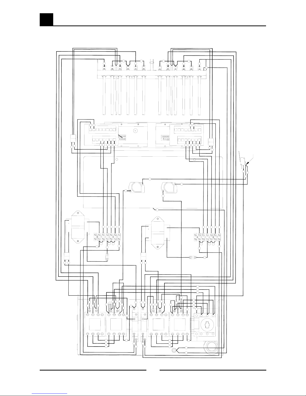
9.4 E44E - Twin Tank Fryer
T
O
P
B
O
T
T
O
M
M
I
C
R
O
S
W
I
T
C
H
G
E
A
R
T
R
A
Y
T
H
E
R
M
O
S
T
A
T
P
A
N
E
L
O
V
E
R
T
E
M
P
L
1
L
2
L
3
N
E
A
R
T
H
1
1
1
2
2
2
3
3
3
7
9
2
3
2
4
2
4
2
5
2
7
4
5
2
6
2
7
2
5
5
1
7
7
3
3
3
8
8
4
4
6
6
6
1
5
5
5
5
4
3
4
4
2
2
2
8
4
2
4
3
5
5
5
4
5
4
4
7
7
7
E
L
E
M
E
N
T
S
5
0
2
6
3
0
1
1
2
9
2
9
1
0
1
0
5
0
5
1
1
1
1
2
4
1
3
4
3
5
3
6
3
7
3
8
3
3
3
3
4
0
3
9
2
2
1
5
1
6
1
7
1
8
1
9
1
4
1
4
2
1
1
3
2
0
3
1
P
R
O
B
E
P
R
O
B
E
B
R
O
W
N
B
R
O
W
N
3
2
F
U
S
E
Q
C
D
O
U
B
L
E
C
O
N
E
C
T
O
R
P
/
N
0
1
3
1
0
7
B
R
O
W
N
B
R
O
W
N
3
8
3
7
3
5
4
1
4
8
4
9
3
6
1
5
2
2
4
6
4
7
1
6
1
8
1
7
4
7
4
6
1
2
2
3
1
9
2
0
3
1
4
2
3
8
3
9
4
9
4
8
F
U
S
E
2
2
3
0

10
Service Contacts
35
Blue Seal Evolution Series E43 / E44 Electric Fryers
Revision 1/
© Moffat Ltd, January 2007
Australia
VICTORIA - MOFFAT PTY
HEAD OFFICE AND MAIN WAREHOUSE
740 Springvale Road Tel (03) 9518 3888
Mulgrave VIC 3170 Fax (03) 9518 3838
Spare Parts Department Free Call 1800 337 963
Fax (03) 9518 3895
NEW SOUTH WALES - MOFFAT PTY
Unit 3/142 James Ruse Drive Tel (02) 8833 4111
Rosehill NSW 2142
Spare Parts Free Call 1800 337 963
Fax (03) 9518 3895
QUEENSLAND - MOFFAT PTY
30 Prosperity Place Tel (07) 3630 8600
Geebung QLD 4034
Spare Parts Free Call 1800 337 963
Fax (03) 9518 3895
WESTERN AUSTRALIA - MOFFAT PTY
67 Howe St Tel (08) 9202 6820
Osbourne Park, WA 6017 Fax (08) 9202 6836
Spare Parts Free Call 1800 337 963
Fax (03) 9518 3895
NATIONAL COVERAGE FOR 24 HOUR SERVICE OR MAINTENANCE DIAL
FREE CALL 1800 622 216 (AUSTRALIA ONLY)
Canada
SERVE CANADA
22 Ashwarren Rd Tel 416-631-0601
Downview Fax 416-631-0315
Ontario M3J1Z5
New Zealand
CHRISTCHURCH - MOFFAT LTD
16 Osborne St Tel (03) 389 1007
PO Box 10-001 Fax (03) 389 1276
Christchurch
Spare Parts Free Call 0800 MOFFAT
(0800 66 33 28)
Fax (03) 381 3616
AUCKLAND - MOFFAT LTD
4 Waipuna Road Tel (09) 574 3150
Mt Wellington Fax (09) 574 3159
Auckland
Spare Parts Free Call 0800 MOFFAT
(0800 66 33 28)

10
Service Contacts
36
Blue Seal Evolution Series E43 / E44 Electric Fryers
Revision 1/
© Moffat Ltd, January 2007
United Kingdom
BLUESEAL LTD
Units 67
Gravely Industrial Park Tel 0121 327 5575
Gravely Park, Erdington Fax 0121 327 9711
Birmingham B24 8TQ
England
United States of America
MOFFAT INC.
3765 Champion Blvd
Winston-Salem Tel 1800 551 8795
NC27115 Fax 336 661 9546
NATIONAL COVERAGE FOR SERVICE OR MAINTENANCE DIAL
FREE CALL 1800 551 8795 (USA ONLY)
 Loading...