

Page 1
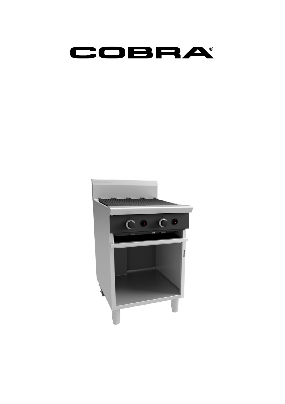
Gas Barbeque
Models:
CB 6 ( 6 00 m m)
CB 9 ( 9 00 m m)
I N S T A L L A T I O N A N D O P E R A T I O N M A N U A L
242355-1
Page 2

The reproduction or copying of any part of this manual by any means whatsoever is strictly forbidden unless authorized
previously in writing by the manufacturer.
In line with policy to continually develop and improve its products, Moffat Ltd. reserves the right to change the
specifications and design without prior notice.
© Copyright Moffat Ltd. March 2019.
Moffat Limited
Rolleston 7675
New Zealand
AUSTRALIA
(fax): +61 (03 9518 3833
Service: (tel): 1800 622 216
Spares: (tel): 1800 337 963
Customer Service: (tel): 1800 335 315
(fax): 1800 350 281
CANADA
Serve Canada
Web: www.servecanada.com
E.Mail: [email protected]
Sales: (tel): 800 551 8795 (Toll Free)
Service: (tel): 800 263 1455 (Toll Free)
NEW ZEALAND
UNITED KINGDOM
Blue Seal
Web: www.blue-seal.co.uk
(fax): +44 121 327 9711
Spares: (tel): +44 121 322 6640
(fax): +44 121 327 9201
Service: (tel): +44 121 322 6644
(fax): +44 121 327 6257
UNITED STATES
Moffat
Web: www.moffat.com
Sales: (tel): 1800 551 8795 (Toll Free)
(tel): +1 336 661 1556
(fax): +1 336 661 9546
Service: (tel): 866 673 7937 (Toll Free)
(tel): +1 366 661 1556
(fax): +1 336 661 1660
REST OF WORLD
Moffat Limited
Page 3

Model Numbers Covered in this Specification
General
Gas Supply Requirements
Gas Connection
Dimensions
Installation Requirements
Unpacking
Assembly
Location
Clearances
Gas Connection
Commissioning
Operation Guide
Description of Controls
Lighting the Pilot Burner
Lighting the Main Burner
General
After Each Use
Daily Cleaning
Weekly Cleaning
Periodic Maintenance
Gas Conversion Procedure
Gas Specifications
Page 4
We are confident that you will be delighted with your Cobra Series Barbeque, and it will become a most
valued appliance in your commercial kitchen.
To ensure you receive the utmost benefit from your new Cobra Appliance, there are two important things
you can do.
Please read this instruction book carefully and follow the directions given. The time taken will be well
spent.
If you are unsure of any aspect of the installation, instructions or performance of your appliance,
contact your Cobra Series appliance dealer promptly. In many cases a phone call could answer your
question.
These instructions are only valid if the country code appears on the appliance. If the code does not
appear on the appliance, refer to the supplier of this appliance to obtain the technical instructions for
adapting the appliance to the conditions for use in that country.
IMPROPER INSTALLATION, ADJUSTMENT, ALTERATION, SERVICE OR MAINTENANCE CAN CAUSE PROPERTY DAMAGE, INJURY OR DEATH.
READ THE INSTALLATION, OPERATING AND MAINTENANCE INSTRUCTIONS THOROUGHLY BEFORE INSTALLING OR SERVICING THIS
APPLIANCE.
INSTRUCTIONS TO BE FOLLOWED IN THE EVENT THE USER SMELLS GAS ARE TO BE POSTED IN A PROMINENT LOCATION. THIS INFORMATION
SHALL BE OBTAINED BY CONSULTING THE LOCAL GAS SUPPLIER.
GREAT CARE MUST BE TAKEN BY THE OPERATOR TO USE THE EQUIPMENT SAFELY TO GUARD IT AGAINST RISK OF FIRE.
THE APPLIANCE MUST NOT BE LEFT ON UNATTENDED.
IT IS RECOMMENDED THAT A REGULAR INSPECTION IS MADE BY A COMPETENT SERVICEMAN TO ENSURE CORRECT AND SAFE
OPERATION OF YOUR APPLIANCE IS MAINTAINED.
DO NOT STORE OR USE GASOLINE OR OTHER FLAMMABLE VAPOURS OR LIQUIDS IN THE VICINITY OF THIS OR ANY OTHER
APPLIANCE.
DO NOT SPRAY AEROSOLS IN THE VICINITY OF THIS APPLIANCE WHILE IT IS IN OPERATION.
2
Page 5
3
Model Covered in this Specification -
A commercial heavy duty, fully modular, gas fired barbeque created for modular kitchens supplied in either
600mm or 900mm wide options. The barbeque is fitted with branding grates and aluminised steel burners,
with individual ‘Hi'-'Lo' gas control to each burner. The burners are fitted with piezo ignited permanent pilot
and flame failure protection for each burner.
- Australia:
- New Zealand:
- United Kingdom:
Category: II
2H3P
(20, 30 / 37).
Flue Type: A1.
NOTE:
(*) Measure burner operating pressure at manifold test point with two burners operating at 'High Flame'
setting. Operating pressure is ex-factory set and is not to be adjusted, apart from when converting between
gases, if required. Refer to ‘Gas Conversion’ Section in this manual for further details.
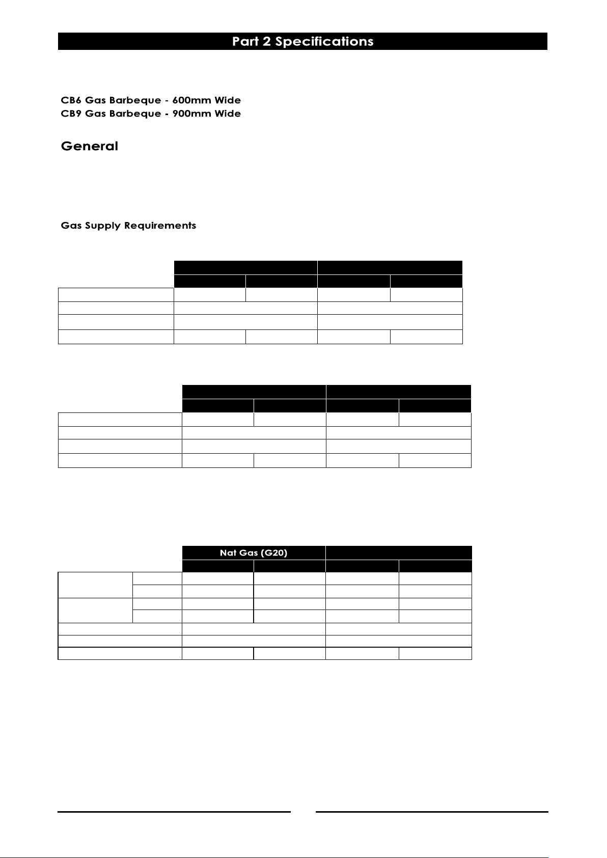
Natural Gas LP Gas (Propane)
CB6 CB9 CB6 CB9
Input Rating 66.0 MJ/hr 100.0 MJ/hr 66.0 MJ/hr 100.0 MJ/hr
Supply Pressure
1.13 - 3.40 kPa 2.75 - 4.50 kPa
Burner Operating Pressure 0.95 kPa 2.60 kPa
Gas Connection
½" BSPT Male ¾" BSPT Male ½" BSPT Male ¾" BSPT Male
Propane (G31)
CB6 CB9 CB6 CB9
Heat Input (nett)
Nominal
18.0 kW 27.kW 18.0 kW 27.kW
Reduced
6.0 kW 9 kW 6.4 kW 9.6 kW
Gas Rate (nett)
Nominal
1.90 m3/hr 2.86 m3/hr 1.40 kg/hr 2.10 kg/hr
Reduced
0.63 m3/hr 0.95 m3/hr 0.50 kg/hr 0.75 kg/hr
Supply Pressure
20 mbar 30 / 37 mbar
Burner Operating Pressure (*)
10 mbar 26 mbar
Gas Connection
½" BSPT Male ¾" BSPT Male ½" BSPT Male ¾" BSPT Male
Natural Gas LP Gas
CB6 CB9 CB6 CB9
Input Rating 66.0 MJ/hr 100.0 MJ/hr 66.0 MJ/hr 100.0 MJ/hr
Supply Pressure
1.13 - 3.40 kPa 2.75 - 4.50 kPa
Burner Operating Pressure
0.95 kPa 2.60 kPa
Gas Connection
½" BSPT Male ¾" BSPT Male ½" BSPT Male ¾" BSPT Male
Page 6
4
- All Other Markets:
NOTE:
(*) Measure burner operating pressure at manifold test point with two burners operating at 'High Flame'
setting.
NAT, LPG & Butane Only - The operating pressure is ex-factory set and is not to be adjusted, apart from
when converting between gasses, if required.
(**) TOWN GAS Only - Burner operating pressure is to be adjusted using the adjustable gas regulator
supplied.
Refer to ‘Gas Conversion and Specifications section of this manual for further details.
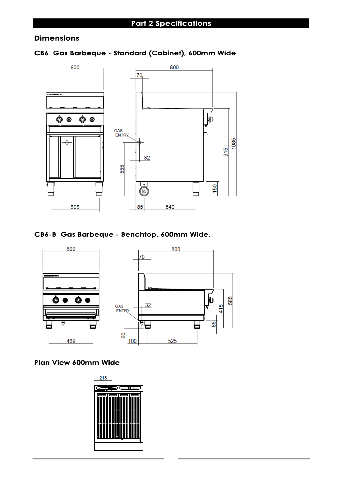
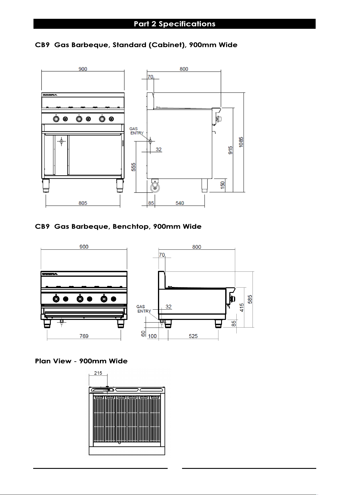
Gas supply connection point is located at the rear of the appliance:-
For CB6 - Approximately 215mm from the left hand side and 535mm from the floor and is entered from
beneath the appliance.
Gas Connection is ½” BSPT male.
For CB9 - Approximately 215mm from the left hand side and 555mm from the floor and is entered from
beneath the appliance.
Gas Connection is ¾” BSPT male.
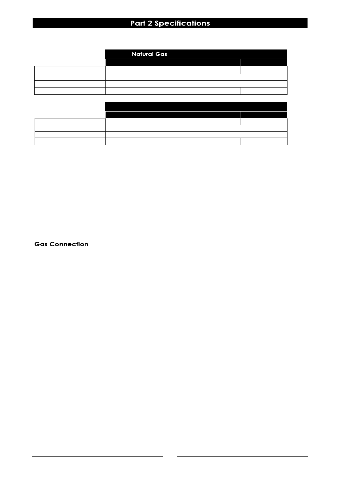
LP Gas (Propane) LP Gas (Butane)
CB6 CB9 CB6 CB9
Input Rating
66.0 MJ/hr 100.0 MJ/hr 66.0 MJ/hr 100.0 MJ/hr
Supply Pressure
2.75 - 4.50 kPa 2.75 - 4.50 kPa
Burner Operating Pressure (*)
2.60 kPa 2.60 kPa
Gas Connection
½" BSPT Male ¾" BSPT Male ½" BSPT Male ¾" BSPT Male
Town Gas (**)
CB6 CB9 CB6 CB9
Input Rating 66.0 MJ/hr 100.0 MJ/hr 66.0 MJ/hr 100.0 MJ/hr
Supply Pressure
1.13 - 3.40 kPa 0.75 - 1.50 kPa
Burner Operating Pressure (*)
0.95 kPa 0.63 kPa
Gas Connection
½" BSPT Male ¾" BSPT Male ½" BSPT Male ¾" BSPT Male
Page 7
5 6 7
Page 8
Page 9
NOTE:
It is most important that this appliance is installed
correctly and that operation is correct before use.
Installation shall comply with local, gas, health and
safety requirements.
This appliance shall be installed with sufficient
ventilation to prevent the occurrence of
unacceptable concentrations of health harmful
substances in the room, the appliance is installed in.
Cobra Series Barbeques are designed to provide
years of satisfactory service and correct installation
is essential to achieve the best performance,
efficiency and trouble-free operation.
This appliance must be installed in accordance with
National installation codes and in addition, in
accordance with relevant National / Local codes
covering gas and fire safety.
Australia / New Zealand:
AS/NZS 5601 - Gas Installations.
United Kingdom:
Gas Safety (Installation and Use) Regulations
1998.
BS6173 - Installation of Catering Appliances.
BS5440 - 1 & 2 Installation Flueing & Ventilation.
Ireland:
IS 820 - Non Domestic Gas Installations.
Installations must be carried out by qualified service
persons only. Failure to install equipment to the
relevant codes and manufacturer’s specifications
shown in this section will void the warranty.
Components having adjustments protected (e.g.
paint sealed) by manufacturer, are only to be
adjusted by an qualified service agent. They are
not to be adjusted by the installation person.
Remove all packaging and transit protection
from the appliance including all protective
plastic coating from the door outer panel and
exterior stainless steel panels.
Check equipment and parts for damage.
Report any damage immediately to the carrier
and distributor.
Report any deficiencies to the distributor who
supplied the appliance.
Check that the available gas supply is correct to
that shown on the rating plate attached to the
inner R/H side, below the grease tray.
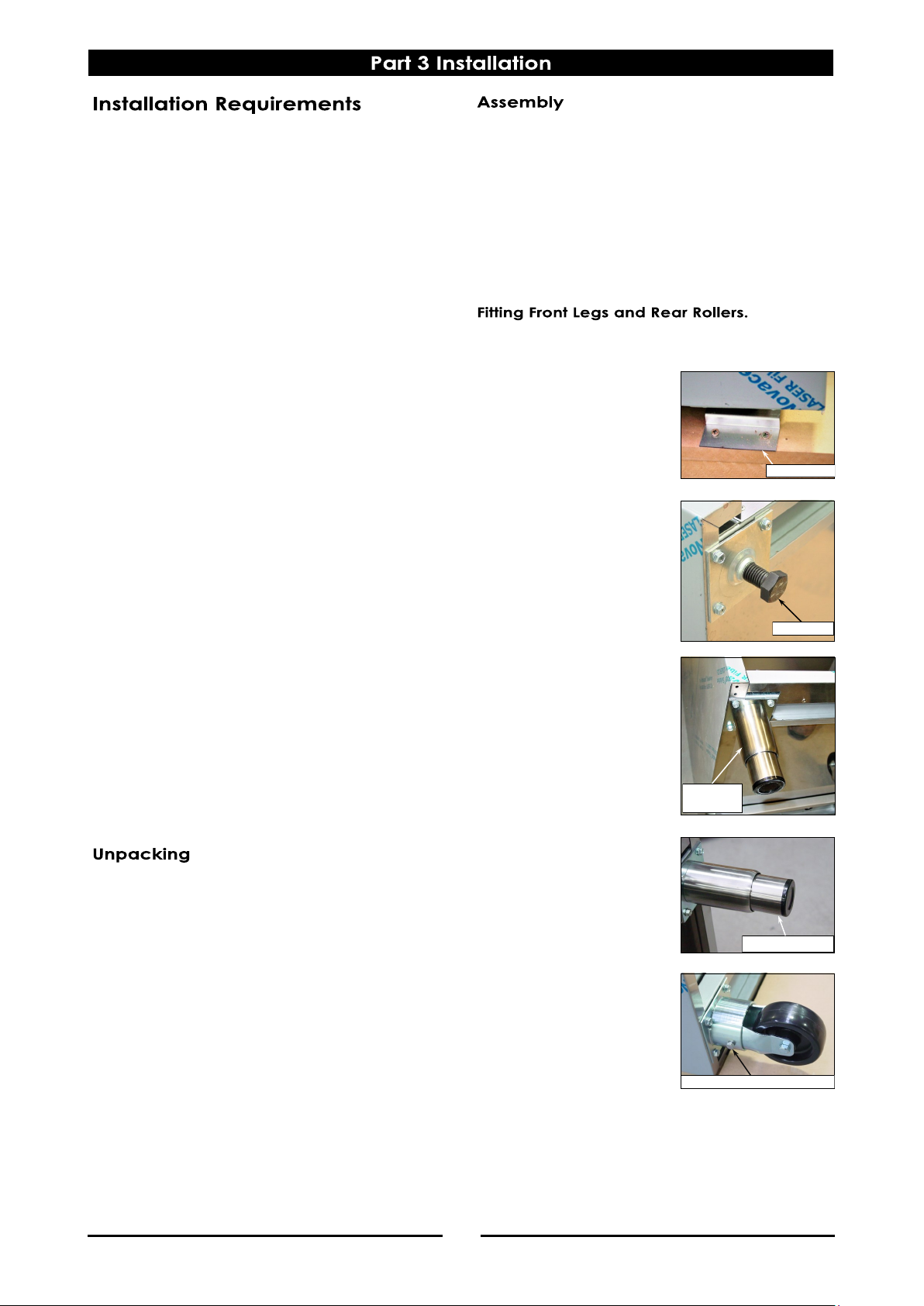
If the Legs and Rear Rollers are not fitted, carry out
the procedure below to fit Front Legs and Rear
Rollers.
NOTE:
This appliance is fitted with adjustable feet to
enable the appliance to be positioned securely and
level. This should be carried out on completion of
the gas connection.
1. Remove all loose components from the top of
the appliance.
2. Remove screws securing
transit plates to the front
corners of the transit
pallet.
3. Tilt the appliance onto it’s
back and unscrew the
transit bolts from the front
leg mounting plates.
4. Remove front legs from
carton and screw onto
the front leg mounting
plates.
NOTE:
The front legs are adjustable.
Once the rear rollers are
fitted and the appliance is in
it’s operating position, the
front legs can be adjusted to
level the appliance.
5. Remove rear rollers from
carton and attach to rear
leg ring plate. Secure
with 10mm bolts supplied.
6. Lift appliance back onto it’s legs / rollers.
7. Place the cooktop in its final operating position
and use the adjustable feet to level the
appliance.
8. Refit all items removed at Item 1 above.
Attach with Bolt supplied.
Transit Bolt.
Transit Plate.
Adjustable Foot
Adjustable
Front Leg
Page 10
8
1. Installation must allow for a sufficient flow of fresh
air for the combustion air supply.
2. This appliance must be installed in a suitably
ventilated room to prevent dangerous build up
of combustion products.
3. Position the appliance in its approximate
working position.
4. All air for burner combustion is supplied from
underneath the appliance. The legs must
always be fitted and no obstructions placed on
the underside or around the base of the
appliance, as obstructions will cause incorrect
operation and / or failure of the appliance.
5. Components having adjustments protected
(e.g. paint sealed) by manufacturer are only to
be adjusted by an qualified service agent. They
are not to be adjusted by the installation person.
NOTE:
Do not obstruct or block the appliances flue. Never
directly connect a ventilation system to the
appliance flue outlet.
NOTE:
Only non-combustible materials can be used in
close proximity to this appliance.
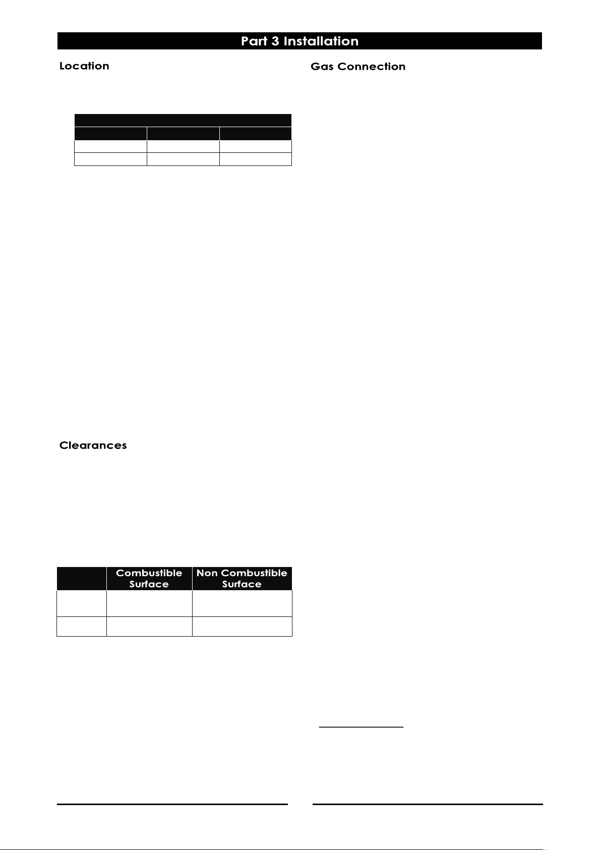
Any gas burning appliance requires adequate
clearance and ventilation for optimum and troublefree operation. The following minimum installation
clearances are to be adhered to:
LH / RH
Side
200mm 0mm
Rear 100mm 0mm
NOTE:
ALL GAS FITTING MUST ONLY BE CARRIED OUT BY A
QUALIFIED SERVICE PERSON.
1. Cobra Model Barbeques do not require an
electrical connection, they function totally on
the gas supply only.
2. It is essential that the gas supply is correct for the
appliance being installed and that adequate
supply pressure and volume are available. The
following checks should be made before
installation is commenced:-
a. The Gas Type the appliance has been
supplied for is shown on coloured stickers
located above the gas entry point and next
to the rating plate. Check that this is correct
for the gas supply the appliance is being
installed for. The gas conversion procedure is
detailed in the ‘Gas Conversion Instruction
Sheet' for this appliance.
b. Supply Pressure required for this appliance is
shown in the “Specifications” section of this
manual. Check the gas supply to ensure that
adequate supply pressure exists.
c. Input Rate of this appliance is also stated on
the rating plate attached to the inner R/H
side, below the grease tray, and in the
“Specifications” section of this manual. The
input rate should be checked against the
available gas supply line capacity. Particular
note should be taken if the appliance is
being added to an existing installation.
NOTE:
It is important that adequately sized piping runs
directly to the connection joint on the appliance,
with as few tees and elbows as possible to give
maximum supply volume.
3. Fit the gas regulator supplied, into the gas supply
line as close to the appliance as possible.
The regulator connections are ½" BSPT female.
The connection is ½" BSPT male.
(Refer to the ‘Specifications’ section for the
gas supply location dimensions).
NOTE:
The gas pressure regulator provided with this
appliance is convertible between Natural Gas and
LPG as per the ‘Gas Conversion Section’ in this
manual.
Ensure the regulator is converted to the correct gas
type that the appliance will operate on.
The regulator outlet pressure is fixed ex-factory for
the gas type that the regulator is converted to and it
is NOT to be adjusted.
4. A suitable joining compound which resists the
breakdown action of LPG must be used on
every gas line connection, unless compression
fittings are used.
Combustion Air Requirements (Minimum)
CB6 CB9
Natural Gas
18 m³/hr 27 m³/hr
LPG / Propane
18 m³/hr 27 m³/hr
Page 11
9
NOTE:
A Manual Isolation Valve must be fitted to the
individual appliance supply line.
5. Correctly locate the appliance into its final
operating position and using a spirit level, adjust
the legs so that the unit is level and at the
correct height.
6. Connect the gas supply to the appliance.
7. Verify the operating pressure is as shown in the
'Specifications Section'.
8. Check all gas connections for leakages using
soapy water or other gas detecting equipment.
NOTE:
The operating pressure to be measured at the
manifold test point and with two burners operating
at the ‘High Flame’ setting.
9. Verify the operating pressure remains correct.
The following commissioning checks must be
carried out before the barbeque is handed over for
use, to ensure that the unit operates correctly and
the operator(s) understand the correct operating
procedure.
1. Before leaving the new installation;
a. Check the following functions in accordance
with the operating instructions specified in
the “Operation” section of this manual.
Light the Pilot Burners.
Light the Main Burners.
Check the Low Fire Burner Operation.
Check the High Fire Burner Operation.
b. Ensure that the operator has been instructed
in the areas of correct lighting, operation,
and shutdown procedure for the appliance.
2. This manual must be kept by the owner for future
reference and a record of Date of Purchase,
Date of Installation and Serial Number of Unit
recorded and kept with this manual. (These
details can be found on the rating plate
attached to the inner R/H side, below the grease
tray. (Refer to the “Gas Connection” section).
NOTE:
If it is not possible to get the appliance to operate
correctly, contact the suppler of this appliance.
DO NOT USE A NAKED FLAME TO CHECK FOR GAS LEAKAGES.
Page 12
10
NOTE:
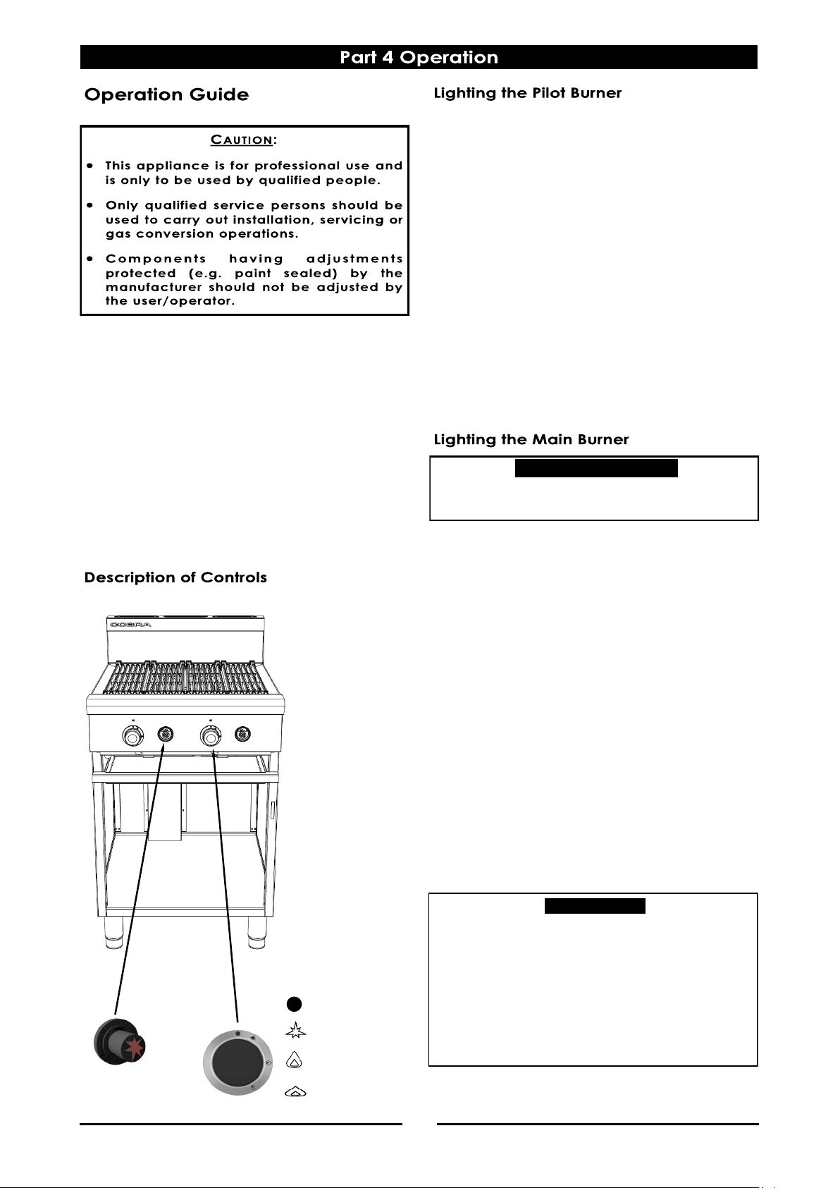
All Barbeque models incorporate the push button
piezo ignition system for each individual pilot burner.
1. Depress the gas control knob and rotate anticlockwise to the ‘PILOT’ position.
2. With the gas control knob held in the depressed
position, depress the piezo igniter button located
on the front control panel to the right of the gas
control knob, until the pilot burner ignites. (Each
depression operation of the piezo igniter button
will generate a single spark). Pilot ignition can
be viewed through openings in the plastic
surround fitted to the piezo igniter button.
3. Hold in the gas control knob for approximately
10-15 seconds, then release. The pilot burner
should remain alight. (If not repeat Items 2 and
3 above).
1. Turn the gas controls anti-clockwise to first stop
(‘FULL’ flame position) and allow the griddle
plates to heat up to the operating temperature.
2. ‘LOW’ flame can be achieved by depressing
the gas control knob and rotating fully anti-
clockwise.
3. For intermediate heat, position the gas control
knob between the ‘HIGH’ and ‘LOW’ positions to
achieve the desired heat.
4. During idle periods, the main burners can be
turned down to maintain an appropriate plate
temperature or the gas controls can be set to
the ‘PILOT’ position as required.
NOTE:
Always set the gas control knob to the ‘HIGH’
position when lighting the main burners.
If the pilot burner goes out during normal
operation, wait 5 minutes before attempting to
re-light the pilot burner.
1. The Cobra Barbeques have been designed to
provide simplicity of operation and 100% safety
protection.
2. Improper operation is therefore almost
impossible, however bad operation practices
can reduce the life of the barbeque and
produce a poor quality product. To use this
barbeque correctly please carefully read the
following sections.
Lighting the Pilot Burner.
Lighting the Main Burner.
Should any abnormal operation like;
- ignition problems,
- abnormal burner flame,
- burner control problems,
- partial or full loss of burner flame in normal
operation,
be noticed, the appliance requires IMMEDIATE
service by a qualified service person and shall not
be used until such service is carried out.
IMPORTANT
Always ensure that the grease tray is emptied regularly
and never allow the grease tray to overflow.
! IMPORTANT
Piezo Igniter
Gas Control Knobs
OFF Position
PILOT Burner
HIGH Flame
LOW Flame
Page 13
11
CORRECT LEV EL FOR FRYING MEDIUM WHEN AT
FRYING TEMPERATURE, KEEP TOPPED UP
INDICATES CORRECT F RYING MEDIUM LEVEL
WHEN COLD
NOTE:
If the Barbeque usage is very high, we
recommend that the weekly cleaning procedure
is carried out on a more frequent basis.
Ensure that protective gloves are worn during the
cleaning process.
DO NOT use harsh abrasive detergents, strong
solvents or caustic detergents as they will
damage the range and burners.
DO NOT use water on the Barbeque while the
grates are still hot as warping may occur. Allow
these items castings to cool and remove for
cleaning.
Grates (Cast Iron)
a. Clean the grates thoroughly with a wire brush
or a flexible spatula.
b. A scraper tool can be used for the removal
of stubborn carbon and deposits.
c. Clean with hot water, a recommended
detergent solution and a scrubbing brush.
Dry all components thoroughly with a dry
cloth.
d. The barbeque should be switched on briefly
to ensure the grates becomes dry. A thin film
of cooking oil should be spread over the
grates in order to form a protective film.
Radiants (Cast Iron)
a. Clean the radiants thoroughly with a wire
brush or a flexible spatula.
b. A scraper tool can be used for the removal
of stubborn carbon and deposits.
c. Clean with hot water, a mild detergent
solution and a scrubbing brush. Dry all
radiants thoroughly with a dry cloth.
Main Burners
a. The main burners can be cleaned with hot
water, a recommended detergent solution
and a scrubbing brush. Ensure that any
excess water is removed from inside the
burners. Dry all burners thoroughly with a dry
cloth.
b. Ensure that the burners are fitted correctly
over the main injectors and are located
properly into the recesses in the barbeque.
Clean the Barbeque regularly. A clean barbeque
looks better, will last longer and will perform better.
Carbonised grease on the surface or on the
barbeque will hinder the transfer of heat from the
cooking surface to the food. This will result in loss of
cooking efficiency.
NOTE:
DO NOT use water on the Barbeque while this
item is still hot as warping and cracking may
occur. Allow the barbeque to cool down before
cleaning.
DO NOT use abrasive detergents, strong solvents
or caustic detergents as they could corrode or
damage the barbeque.
In order to prevent rust forming on the barbeque,
ensure that any detergent or cleaning material
has been completely removed after each
cleaning. The appliance should be switched on
briefly to ensure the barbeque becomes dry. Oil
or grease should be spread over the barbeque
cooking surface in order to form a thin protective
greasy film.
To keep your barbeque clean and operating at
peak efficiency, follow the procedures shown
below:-
Clean the barbeque regularly to remove any food
debris.
1. The spill tray should be checked and emptied
frequently to prevent overflow and spillage.
Remove the spill tray while still warm so that the
grease is in a liquid state. Empty any grease
from the tray and wash thoroughly in the same
manner as any cooking utensil.
2. Remove the grates and radiants and thoroughly
clean with the splash back, interior and exterior
surfaces of the barbeque with hot water, a
detergent solution and a soft scrubbing brush.
3. Brush the barbeque surface with a soft bristled
brush. Any carbon deposits should be removed
using a scraper tool followed by wiping with a
cloth to prevent accumulation of food deposits.
Page 14
12
NOTE:
All maintenance operations should only be carried
out by a qualified service person.
To achieve the best results cleaning must be regular
and thorough and all controls and mechanical
parts should be checked and adjusted periodically
by a qualified service person. If any small faults
occur, have them attended to promptly. Don't wait
until they cause a complete breakdown. It is
recommended that the appliance is serviced every
6 months.
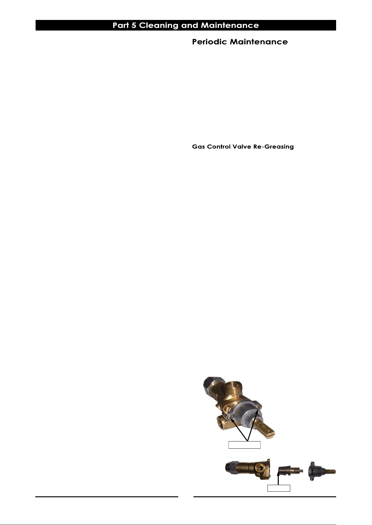
The gas control valve should be dismantled and
greased every 6 months to ensure the correct
operation of the gas control valve.
To carry out this operation;a. Remove the gas control knobs from the gas tap
spindles by pulling the knobs away from the
control panel.
b. Remove the drip tray from the appliance.
c. Remove the two screws on the underside of the
control panel, securing the control panel to the
hob.
d. Remove the control panel from the front of the
appliance.
e. Remove the 2 screws holding shaft plate to gas
control body and remove control shaft and
plate. Note orientation of shaft for correct
re-assembly.
f. Using needle nose pliers or similar, pull out gas
control spindle, again noting its orientation.
g. Apply a suitable high temperature gas cock
grease or lubricant such as ROCOL - A.S.P (Anti
scuffing paste) / Dry Moly Paste to the outside of
spindle.
h. Replace spindle and re-assemble the gas
control in reverse order.
i. Refit the control panel to the appliance and
secure with 2 screws.
j. Refit the knobs to the gas control valve spindles.
Stainless Steel Surfaces
a. Clean the exterior surfaces of the barbeque
with hot water, a mild detergent solution and
a soft scrubbing brush. Note that the gas
control knobs are a push fit onto the gas
control valve spindles and can be removed
to allow cleaning of the front control panel.
b. Baked on deposits or discolouration may
require a good quality stainless steel cleaner
or stainless steel wool. Always apply cleaner
when the appliance is cold and rub in the
direction of the grain.
c. To remove any discolouration, use an
approved stainless steel cleaner or stainless
steel wool. Always rub in the direction of the
grain.
d. Remove the grease tray and clean with a
mild anti bacterial detergent and hot water
solution using a soft bristled brush.
e. Dry the grease tray thoroughly with a dry
cloth.
f. Dry all components thoroughly with a dry
cloth and polish with a soft dry cloth.
Two Screws
Spindle
Page 15

13
Pilot won’t light. No gas supply.
Blocked pilot injector.
Ensure gas isolation valve is turned
‘On’ and bottles are not empty.
Call service provider.
Pilot goes out when gas control
knob is released.
Releasing knob before the
thermocouple has heated.
Pilot flame too small.
- Gas pressure too low.
- Partially blocked pilot injector.
Thermocouple faulty.
Hold knob in for at least 20
seconds following ignition of
pilot.
Call service provider.
Call service provider.
Main burner will not light. Incorrect supply pressure.
Faulty gas control.
Call service provider.
Call service provider.
This section provides an easy reference guide to the more common problems that may occur during
operation of your equipment. The fault finding guide in this section is intended to help you correct, or at
least accurately diagnose problems with your equipment.
Although this section covers the most common problems reported, you may encounter a problem not
covered in this section. In such instances, please contact your local authorised service agent who will make
every effort to help you identify and resolve the problem. Please note that the service agent will require the
following information:-
Model Trade Name and Serial Number of the Appliance. (both can be found on the Rating Plate located
Page 16
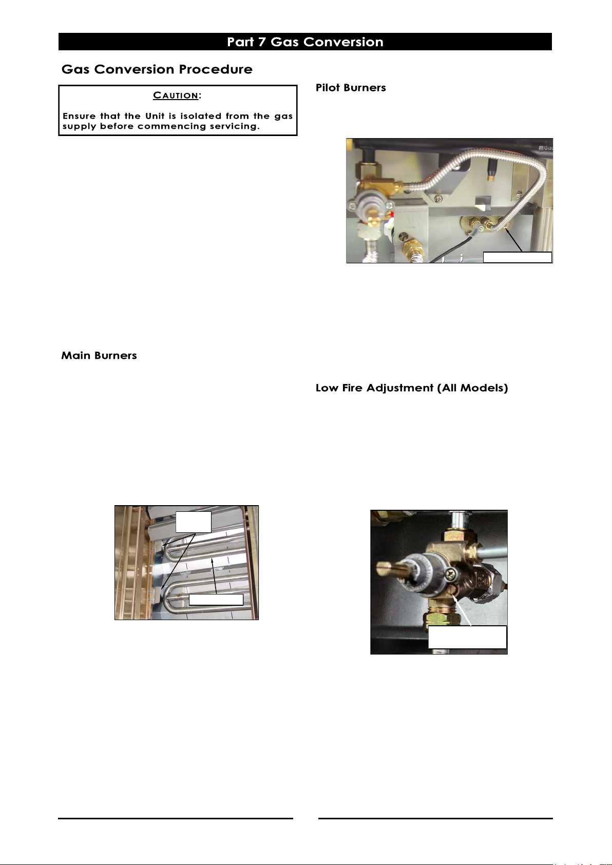
14
NOTE:
These conversions should only be carried out
by qualified persons. All connections must be
checked for leaks before re-commissioning the
appliance.
Adjustment of components that have
adjustments / settings sealed (e.g. paint
sealed) can only be adjusted in accordance
with the following instructions and shall be
re-sealed before re-commissioning this
appliance.
For all relevant gas specifications refer to the
Gas Specifications table at the end of this
section.
1. Remove the following:-
Gas control knobs.
Control Panel.
Chargrill castings / griddle plates and inner
radiants.
Main burners.
2. Remove main burner injectors and replace with
correct size injectors as shown in ‘Gas
Specifications Tables’ at rear of this section.
3. Check / adjust main burner aeration shutter as
shown in ‘Gas Specifications Tables’ at rear of
this section.
4. Refit the following:-
Main burners.
Inner radiants, chargrill castings / griddle
plates.
1. Disconnect the following:-
Gas supply tube to pilot burner.
2. Remove pilot injectors and replace with correct
size pilot injectors as shown in ‘Gas
Specifications Tables’ at rear of this section.
3. Re-connect the following:-
Gas supply tube to pilot burner.
Inner radiants, chargrill castings / griddle
plates.
1. Light main burners and check flame size on
‘Low’ setting.
Adjust low fire adjustment screw on burner
gas control valves by screwing adjustment
screw fully ‘In’ and then unscrewing by the
measurement shown in ‘Gas Specifications’
table at the rear of this Section, to obtain the
desired flame size.
NOTE:
‘Low Fire Adjustment Screw’ should be sealed with
coloured paint on completion of low fire
adjustment.
2. Refit control panel.
3. Refit gas control knobs.
Main Burner
Shell
Brackets
Low Fire
Adjustment Screw
Gas Supply Tube
Page 17
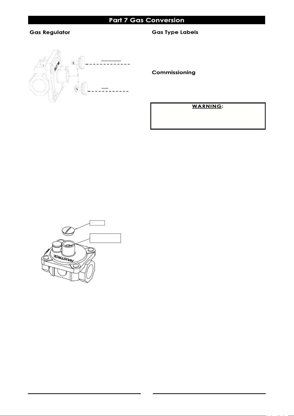
15
- NAT Gas / LPG / Butane Only.
NOTE:
The regulator supplied is convertible between
Natural Gas and LP Gas, but it’s outlet pressure is
fixed ex-factory and is NOT to be adjusted.
1. Ensure that the gas supply is turned 'Off' at the
mains.
2. Unscrew the hexagonal cap (23mm A/F) from
the regulator.
3. Un-clip the plastic pin from the cap, reverse the
pin and re-fit it back to the cap the correct way
for the gas type to be used. (Either ‘LP’ or ‘NAT’
should be visible on the flank of the pin once refitted to the cap).
4. Screw the cap back into the regulator hand
tight only.
- Town Gas Only.
1. Unscrew and remove the slotted cap from the
regulator.
2. Turn on the gas supply and the appliance.
3. Adjust the pressure djusting nut to achieve the
correct burner operating pressure.
NOTE:
The operating pressure is to be measured at the
manifold test point and with two burners operating
at the “High Flame” setting.
4. Verify the operating pressure remains correct
(Re-adjust the regulator if required).
5. Screw the cap nut back onto the regulator.
NOTE, Pin rotated
for Natural Gas
NOTE, Pin rotated
for LPG
Pressure Adjusting
Screw
Cap Nut
On completion of the gas conversion, replace gas
type labels located at:-
- The rear of the unit, above gas connection.
- Beside the rating plate.
Before leaving the converted installation;
1. Check all gas connections for leakages using
soapy water or other gas detecting equipment.
2. Check the following functions in accordance
with the operating instructions specified in the
'Operation' section of the Installation and
Operation Manual.
Light the Pilot Burners.
Light the Main Burners.
Check the Low Fire burner operation.
Check the High Fire burner operation.
Ensure that all controls operate correctly.
Ensure that the operating pressure remains
correct.
3. Ensure any adjustments done to components
that have the adjustments / settings sealed (e.g.
paint sealed) are re-sealed.
NOTE:
If it is not possible to get the appliance to operate
correctly, shut off the gas supply and contact the
supplier of this unit.
DO NOT USE A NAKED FLAME TO CHECK FOR GAS
LEAKAGES.
Page 18
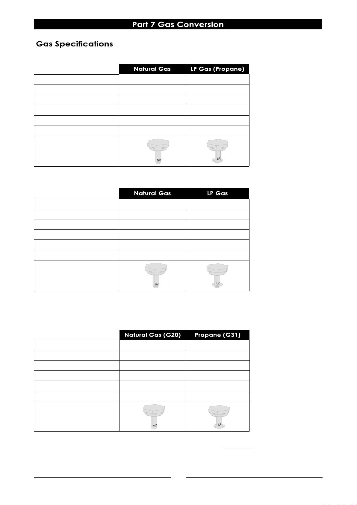
16
- Australia:
- New Zealand:
- United Kingdom:
Category: II
2H3P
(20, 30 / 37).
Flue Type: A1.
NOTE:
(*) Measure burner operating pressure at manifold test point with two burners operating at full setting.
Operating pressure is ex-factory set and not to be adjusted, apart from when converting between gases,
if required. (Refer to details in this section for further information.
Main Burner Injectors
2.70mm 1.65mm
Pilot Burner Injectors
0.45 0.30
Low Fire Adjustment
11/4 turns out (ccw) ½ turn out (ccw)
Supply Pressure
1.13 - 3.40 kPa 2.75 - 4.50 kPa
Burner Operating Pressure (*)
0.95 kPa 2.6 kPa
Main Burner Aeration Shutter
Fully Open Fully Open
Gas Regulator Cap Screw
Main Burner Injectors
2.70 mm 1.65 mm
Pilot Burner Injectors
0.45 0.30
Low Fire Adjustment
11/4 turns out (ccw) ½ turn out (ccw)
Supply Pressure
20 mbar 30 / 37 mbar
Burner Operating Pressure (*)
10 mbar 26 mbar
Main Burner Aeration Shutter
Fully Open Fully Open
Gas Regulator Cap Screw
Main Burner Injectors
2.70mm 1.65mm
Pilot Burner Injectors
0.45 0.30
Low Fire Adjustment
11/4 turns out (ccw) ½ turn out (ccw)
Supply Pressure
1.13 - 3.40 kPa 2.75 - 4.50 kPa
Burner Operating Pressure (*)
0.95 kPa 2.6 kPa
Main Burner Aeration Shutter
Fully Open Fully Open
Gas Regulator Cap Screw
Page 19
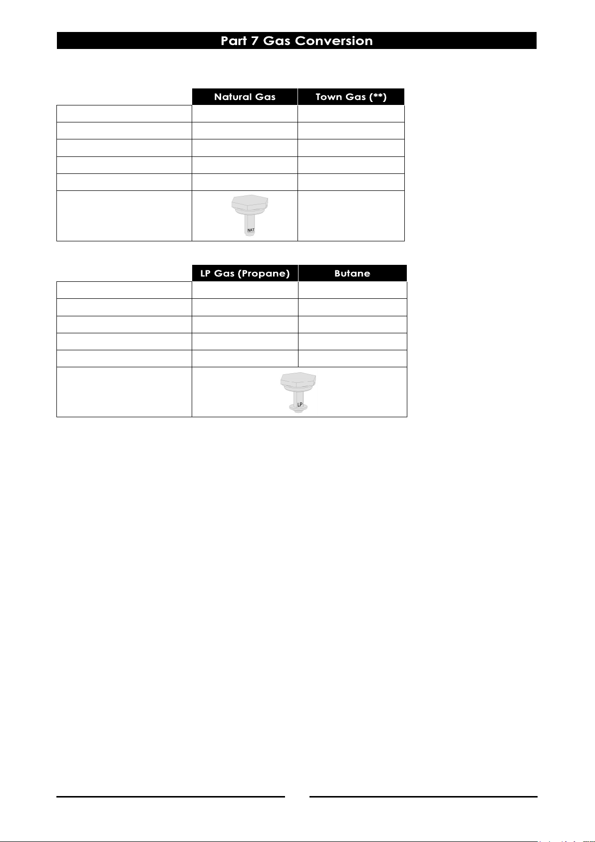
17
- All Other Markets:
NOTE:
(*) Measure burner operating pressure at manifold test point with two burners operating at 'High Flame'
setting.
NAT, LPG & Butane Only - The operating pressure is ex-factory set and is not to be adjusted, apart from
when converting between gasses, if required.
(**) TOWN GAS Only - Burner operating pressure is to be adjusted using the adjustable gas regulator
supplied.
Refer to the ‘Gas Conversion and Specifications section of this manual for further details.
Main Burner Injectors
2.70mm 4.50mm
Pilot Burner Injectors
0.45 0.75
Low Fire Adjustment
11/4 turns out (ccw) 2 turns out (ccw)
Burner Operating Pressure (*)
0.95 kPa 0.63 kPa
Main Burner Aeration Shutter
Fully Open Fully Open
Gas Regulator Cap Screw
Adjustable Regulator
(Adjust to the Burner
Operating Pressure
specified)
Main Burner Injectors
1.65mm 1.55mm
Pilot Burner Injectors
0.30 0.30
Low Fire Adjustment
½ turn out (ccw) ½ turn out (ccw)
Burner Operating Pressure (*)
2.6 kPa 2.6 kPa
Main Burner Aeration Shutter
Fully Open Fully Open
Gas Regulator Cap Screw
Page 20
18
Replacement Parts List
When ordering spare parts, please quote the part number and the description as listed below. If the part
required is not listed below, request the part by description and quote model number and serial number
which is shown on the rating plate.
Controls
230441 Main Burn er.
227404 Gas Co ntrol Valve.
019218 Thermocouple M9 x 1, 450mm.
037270 Burner Injector (Natu ra l) Ø 2.70mm.
037165 Burner Injector (LPG) Ø 1.65mm.
037155 Burner Injector (Butane) Ø 1.55 mm.
037450 Burner Injector (Town Gas) Ø 4.50mm.
227508 Piezo Ignitor.
242362 Control Knob.
019464K Pil ot Burner Kit.
018972 Pilot Orifice (Natural) 0 .45.
018971 Pilot Orifice (LPG / Bu tane) 0.30 .
026393 Pilot Orifice (Town Gas) 0.75.
019624 I gniti on HT Electrode.
229731 I gniti on HT Lead 250mm.
General
229870 Burner Radiant Casting.
229869 Top Gr ate Casting.
242306 Drip Tray (CB6).
242307 Drip Tray (CB9).
242352 Leg.Assembl y (150mm) c/w Leg Plate.
229674 Rear R oller Assy.
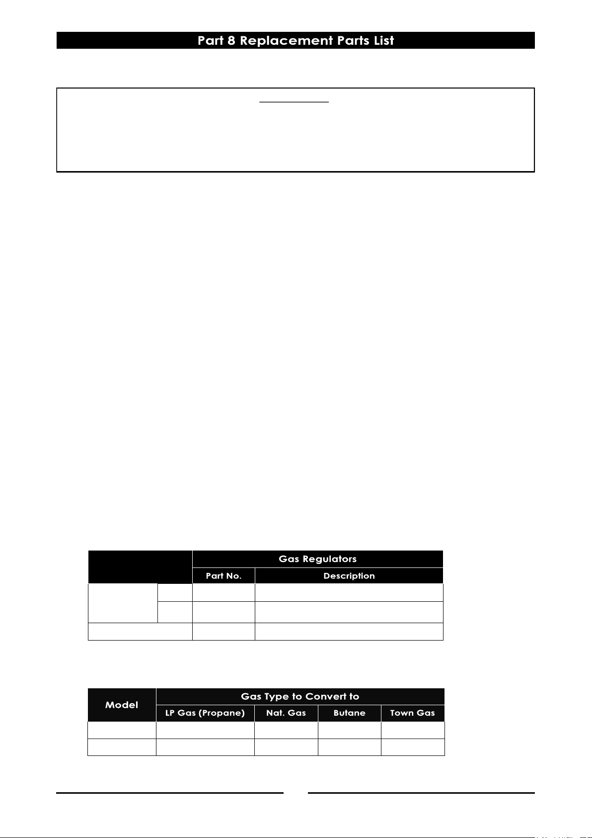
Regulators
Gas Conversion Kits
IMPORTANT:
Only genuine qualified replacement parts should be used for the servicing and repair of this appliance.
The instructions supplied with the parts should be followed when replacing components.
For further information and servicing instructions, contact your nearest qualified service branch (contact
details are as shown on the reverse of the front cover of this manual).
Gas Type
Nat. Gas
LPG
Butane
CB6 228533 ½” BSPT F/F Con verti ble.
228531 ¾” BSPT F/F Convertible CB9
230185 ¾” BSPT F/F Adjustabl e.
Town Gas
CB6 231562 231561 231563 231564
CB9 240859 240858 240860 240861
Page 21

 Loading...