


BD300
Blue Ribbon BD300, BD300-10, BD300-12, BD300-11, BD300-14 Instruction Manual
...
Blue Ribbon Corporation
Instruction Manual
Model BD300
Analog Input
Process Meter
• 0-20 mA, 4-20 mA, 0-5 V, 1-5 V, and ±10 V Inputs
• NEMA 4X, IP65 Front
• Universal 85-265 VAC,or 12/24 VDC Input Power Models
• Large Dual-Line 6-Digit Display, 0.60” & 0.46”
• Dual-Scale for some Level Applications - Single Input
• Sunlight Readable Display Models
• Isolated 24 VDC Transmitter Power Supply
• Signal Input Conditioning for Flow & Round Horizontal Tanks
• Programmable Display & Function Keys
• 32-Point, Square Root, or Exponential Linearization
• Multi-Pump Alternation Control
• 2 or 4 Relays + Isolated 4-20 mA Output Options
• External 4-Relay & Digital I/O Expansion Modules
• USB, RS-232, RS-485 Serial Communication Options
• Tare Function
• Modbus® RTU Communication Protocol Standard
• Configure, Monitor, and Datalog from a PC with
Free BULLDOG Pro Software
Model BD300 Analog Input Process Meter Instruction Manual
DISCLAIMER:
The information contained in this document is subject to change without notice. Blue Ribbon Corp. makes no representations
or warranties with respect to the contents herein adn specifically disclaims any implied warranties of merchantability or
fitness for a particular purpose.
CAUTION:
instructions prior to installation
and operation of the meter.
R
ead complete
WARNING:
Risk of
electric shock or
personal injury.
This product is not recommended for life support
applications or applications where malfunctioning
could result in personal injury or property loss.
Anyone using this product for such applications does
WARNING!
so at his/her own risk. Blue Ribbon Corporation
shall not be held liable for damages resulting from
such improper use.
Limited Warranty
Blue Ribbon Corporation warrants this product against defects in material or
workmanship for the specified period under “Specifications” from the date of
shipment from the factory. Blue Ribbon’s liability under this limited warranty shall
not exceed the purchase value, repair, or replacement of the defective unit.
Registered Trademarks
All trademarks mentioned in this document are the property of their respective
owners.
© 2011-2012 Blue Ribbon Corporation. All rights reserved.
www.blueribboncorp.com
2

Table of Contents
1. IntroductIon . . . . . . . . . . . . . . . . . . . . 1
2. orderIng InformatIon . . . . . . . . . . . . . . . . 2
3. SpecIfIcatIonS . . . . . . . . . . . . . . . . . . . . 4
3.1. General. .....................................4
3.2. Process Input. ................................6
3.3. Relays. . .....................................7
3.4. ISOLATED 4-20 mA TRANSMITTER OUTPUT. .........8
®
3.5. MODBUS
3.6. COMPLIANCE INFORMATION. ....................9
RTU SERIAL COMMUNICATIONS. .........8
3.7. ELECTROMAGNETIC COMPATIBILITY. ...............9
4. Safety InformatIon . . . . . . . . . . . . . . . . 10
5. InStallatIon . . . . . . . . . . . . . . . . . . . . 10
5.1. Unpacking. .................................10
5.2. Panel Mounting Instructions. ....................11
5.3. Conguration for 12 or 24 VDC Power Option. ......13
5.4. Transmitter Supply Voltage Selection (P+, P-). ......14
5.5. Connections. .................................14
Model BD300 Analog Input Process Meter - Instruction Manual
6. Setup and programmIng . . . . . . . . . . . . . 22
6.1. Front Panel Buttons and Status LED Indicators. .....23
6.2. Display Functions & Messages. ..................24
6.3. Main Menu. .................................28
6.4. Setting Numeric Values. .......................29
6.5. Setting Up the Meter (
6.6. Setting the Relay Operation (
6.7. Relay and Alarm Operation Diagrams. ............44
6.8. Relay Operation Details. .......................52
6.9. Scaling the 4-20 mA Analog Output (
6.10. Reset Menu (
6.11. Control Menu (
6.12. Setting Up the Password (
6.13. Advanced Features Menu. ......................66
rESEt). ...........................63
Contrl
SEtuP). ...................30
rELAy). .............41
Aout). ........62
). ........................63
PASS). .................64
7. meter operatIon . . . . . . . . . . . . . . . . . 83
7.1. Front Panel Buttons Operation. ..................83
7.2. Function Keys Operation. ......................84
7.3. F4 Operation. ................................84
7.4. Maximum/Minimum Readings. ..................84
8. troubleShootIng . . . . . . . . . . . . . . . . . 85
8.1. Diagnostics Menu (d iAG). ......................85
8.2. Reset Meter to Factory Defaults. .................86
8.3. Troubleshooting Tips. .........................91
8.4. Alphabetical List of Display Functions & Messages. ..92
9. how to contact blue rIbbon . . . . . . . . . 101
Model BD300 Analog Input Process Meter - Instruction Manual

Table of Figures
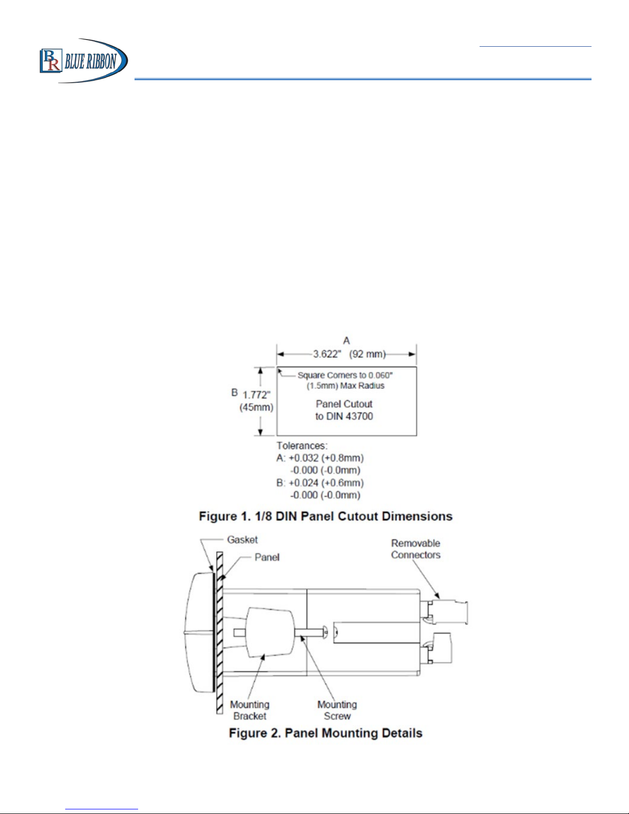
Figure 1. 1/8 DIN Panel Cutout Dimensions ................................................ 11
Figure 2. Panel Mounting Details ................................................................ 11
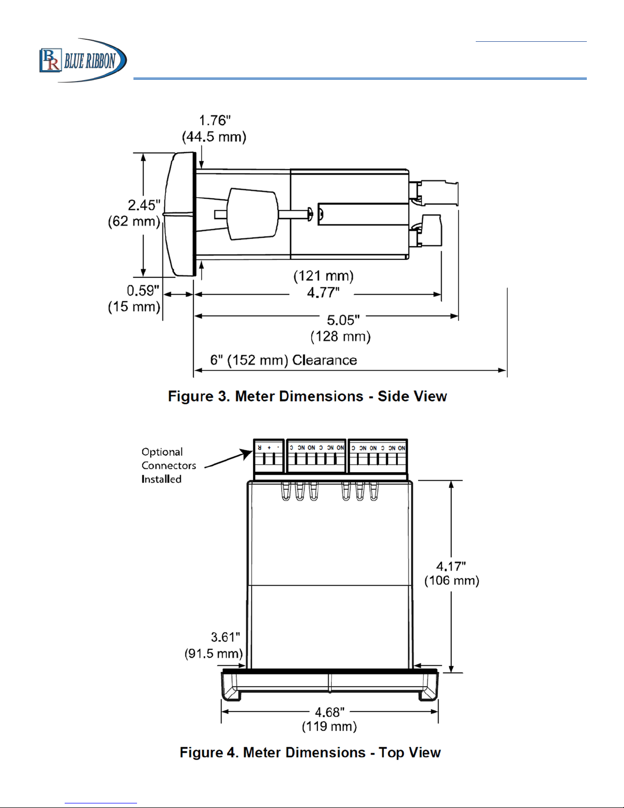
Figure 3. Meter Dimensions - Side View ..................................................... 12
Figure 4. Meter Dimensions - Top View ....................................................... 12
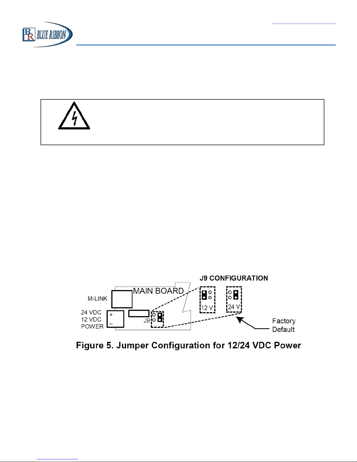
Figure 5. Jumper Conguration for 12/24 VDC Power ................................ 13
Figure 6. Transmitter Supply Voltage Selection ........................................... 14
Figure 7. Connector Labeling for Fully Loaded BD300 ................................ 15
Figure 8. Power Connections .......................................................................15
Figure 9. Transmitters Powered by Internal Supply .................................... 16
Figure 10. Transmitter Powered by Ext. Supply or Self-Powered .................. 16
Figure 11. Voltage Input Connections ............................................................ 17
Figure 12. Relay Connections ......................................................................... 17
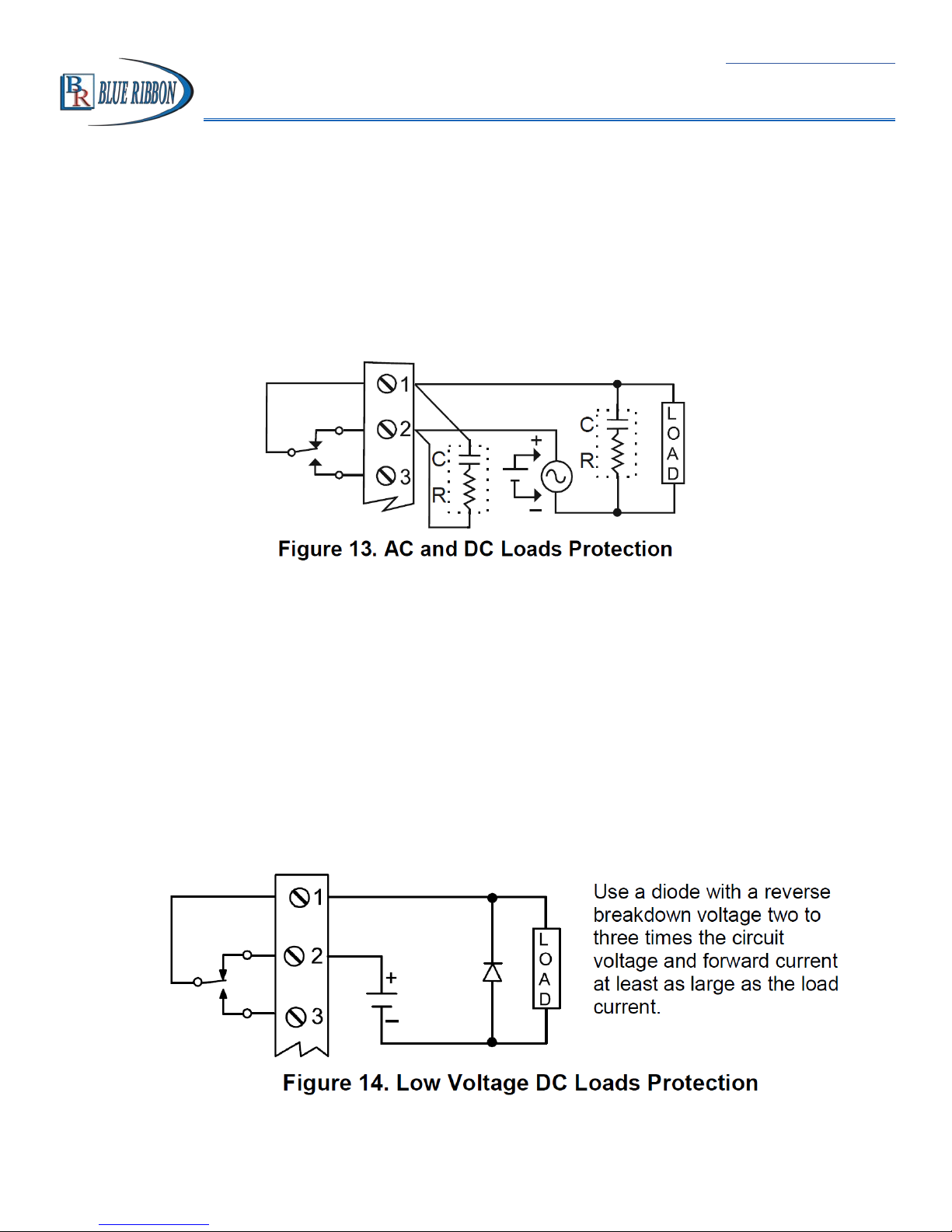
Figure 13. AC and DC Loads Protection ......................................................... 18
Figure 14. Low Voltage DC Loads Protection ................................................. 18
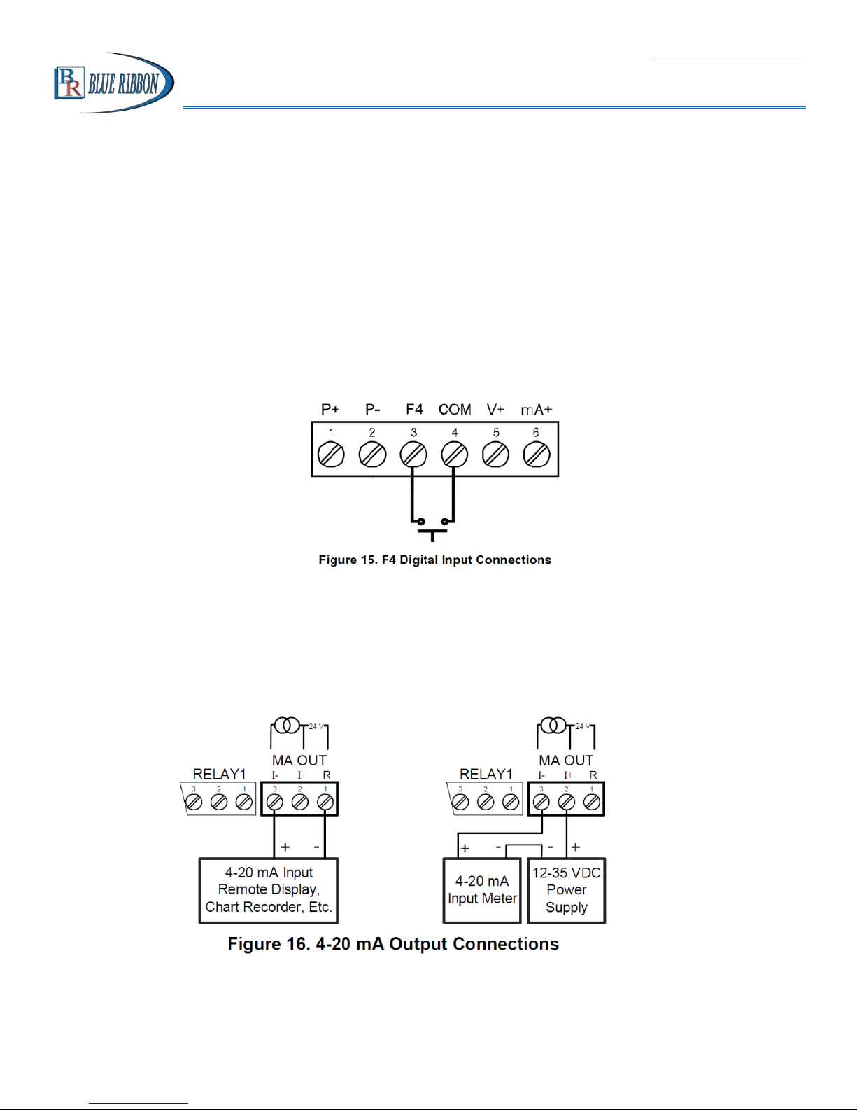
Figure 15. F4 Digital Input Connections ........................................................ 19
Figure 16. 4-20 mA Output Connections ....................................................... 19
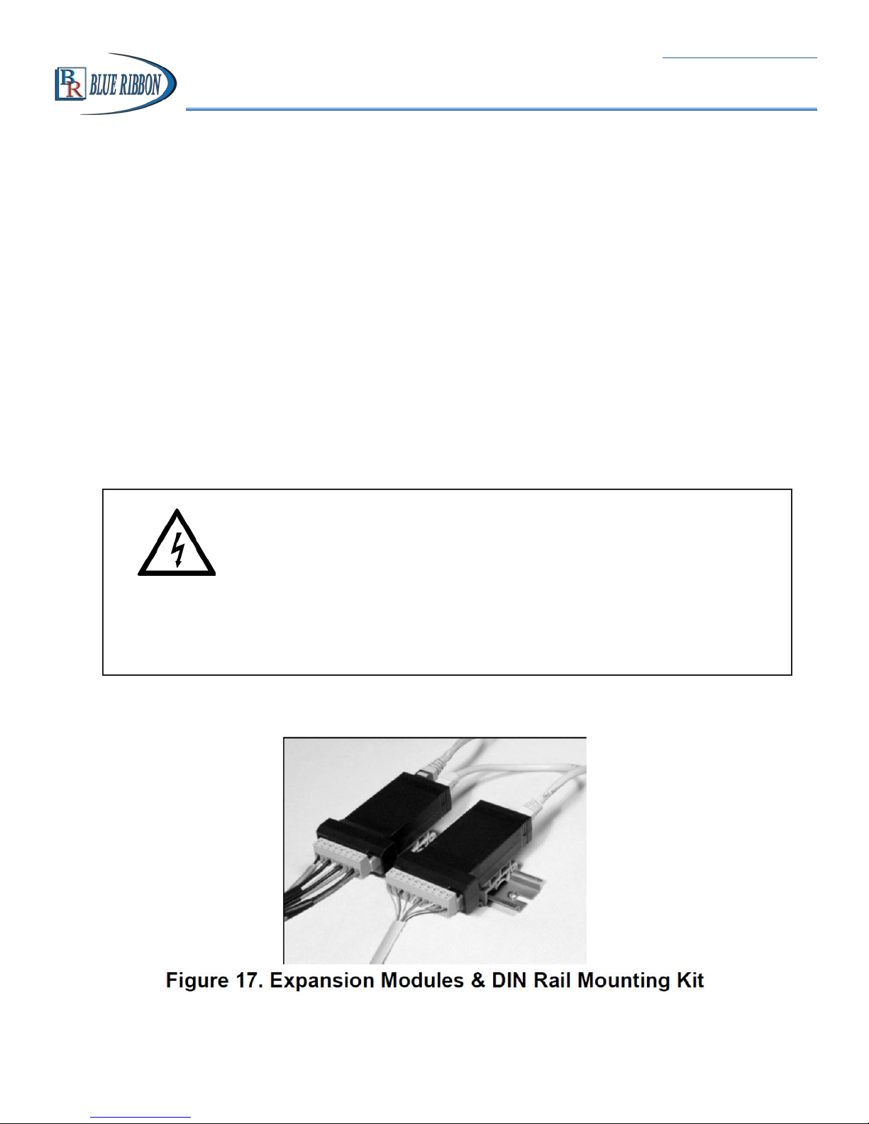
Figure 17. Expansion Modules & DIN Rail Mounting Kit ............................... 20
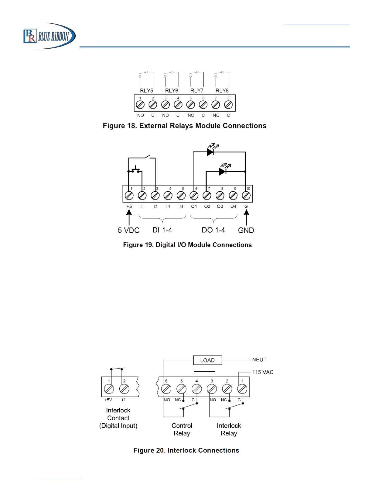
Figure 18. External Relays Module Connections ............................................ 21
Figure 19. Digital I/O Module Connections ................................................... 21
Figure 20. Interlock Connections ................................................................... 21
Figure 21. Acknowledge Relays w/Function Key or Digital Input ................. 57
Figure 22. 1/8 DIN Panel Cutout Template .................................................... 97
Model BD300 Analog Input Process Meter - Instruction Manual

Return to Table of Contents
Model BD300 Analog Input Process Meter Instruction Manual
DISCLAIMER:
The information contained in this document is subject to change without notice.
Blue Ribbon Corp. makes no representations or warranties with respect to the contents herein adn specifically disclaims any implied warranties of merchantability or
fitness for a particular purpose.
1. IntroductIon
The BULLDOG BD300 is a multi-purpose, easy to use digital process meter ideal for
level, flow rate, temperature, or pressure transmitter applications. It accepts current
and voltage signals (e.g. 4-20 mA, 0-10 V). Three of the front panel buttons can be
custom-programmed for a specific operation. The analog input can be scaled to
display the process in two different scales; for example the main display could indicate
level in feet and the second display could indicate the volume in gallons.
The basic model includes an isolated 24 VDC transmitter power supply that can be
used to power the input transmitter or other devices. An additional isolated 24 VDC
power supply is included with the 4-20 mA output option. A digital input is standard.
A fully loaded BD300 meter has the following: four SPDT relays, 4-20 mA output, and two
24 VDC power supplies. The BD300 capabilities may be enhanced by adding the
following external expansion modules: four SPST relays (creating an eight-relay process
meter), two digital I/O modules with four inputs and four outputs each, and USB, RS-232
or RS-485 communication adapters.
The eight relays can be used for alarm indication or process control applications, such as
pump alternation control. The 4-20 mA isolated output, Modbus RTU serial
communications, and digital I/O options make the BD300 an excellent addition to any
system.
1
Model BD300 Analog Input Process Meter Instruction Manual
2. orderIng InformatIon
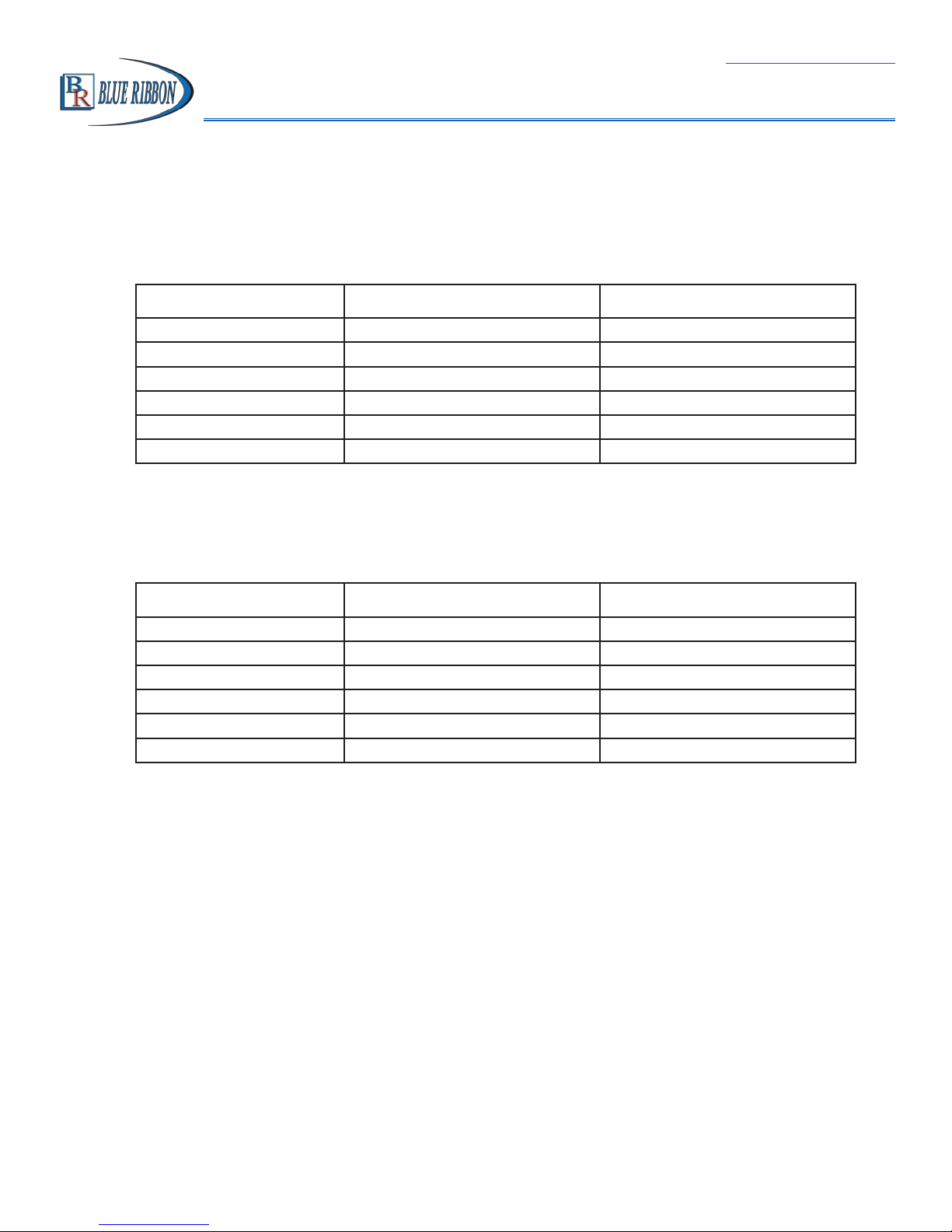
2.1. Standard Models
85-265 VAC Model 12/24 VDC Options Installed
BD300-10 BD300-20 No Options
BD300-12 BD300-22 2 Relays
BD300-11 BD300-21 4-20 mA Output
BD300-14 BD300-24 4 Relays
BD300-13 BD300-23 2 Relays & 4-20 mA Output
BD300-15 BD300-25 4 Relays & 4-20 mA Output
Return to Table of Contents
2.2. SunBright Display Models
85-265 VAC Model 12/24 VDC Options Installed
BD300-10X BD300-20X No Options
BD300-12X BD300-22X 2 Relays
BD300-11X BD300-21X 4-2 mA Output
BD300-14X BD300-24X 4 Relays
BD300-13X BD300-23X 2 Relays & 4-20mA Output
BD300-15X BD300-25X 4 Relays & 4-20mA Output
2
Model BD300 Analog Input Process Meter Instruction Manual
2.3. Accessories
Model Description
BDRMK DIN rail mounting kit for two expansion modules
BDXM 4 SPST (Form A) relays
BDIO 4 Digital inputs & 4 digital outputs (2 may be connected)
BDCCC Meter copy cable
BD232SA RS-232 serial adapter
BD422SA RS-485 serial adapter
BDI232-422/485 RS-232 to RS-422/485 isolated converter
BDN232-422/485 RS-232 to RS-422/485 non-isolated converter
BDUSBSA USB serial adapter
BDNUSB-232 USB to RS-232 non-isolated converter
BDIUSB-422/485 USB to RS-422/485 isolated converter
BDNUSB-422/485 USB to RS-422/485 non-isolated converter
BD6901 Suppressor (snubber): 0.01 µF/470 Ω, 250 VAC
Return to Table of Contents
2.4. Enclosures
Model Description
BD281 1 Meter Plastic NEMA 4X Enclosure
BD282 2 Meter Plastic NEMA 4X Enclosure
3

Model BD300 Analog Input Process Meter Instruction Manual
3. SpecIfIcatIonS
Except where noted, all specifications apply to operation at +25 °C (+77 °F).
3.1. General
Return to Table of Contents
DISPLAY
DISPLAY INTENSITY
DISPLAY UPDATE RATE
OVERRANGE
UNDERRANGE
DISPLAY ASSIGNMENT
PROGRAMMING METHODS
NOISE FILTER
FILTER BYPASS
RECALIBRATION
MAX/MIN
DISPLAY
PASSWORD
POWER OPTIONS
ISOLATED TRANSMITTER
POWER SUPPLY
NON-VOLATILE MEMORY
FUSE
NORMAL MODE REJECTION
ISOLATION
OVERVOLTAGE CATEGORY
Main display: 0.60” (15mm) high, red LEDs
Second display: 0.46” (12mm) high, red LEDs
6 digits each (-99999 to 999999), with lead zero blanking
Eight user selectable intensity levels
5/second (200 ms)
Display flashes 999999
Display flashes -99999
The main (Big) and small (Little) displays may be assigned to PV1, PV2, PCT, d
r4-u, d gross, d-nt-g, max/min max & min, set points, units (small display only, or
Modbus input.
Four front panel buttons, digital inputs, PC and BULLDOG Pro software, Modbus
registers, or cloning using Copy function.
Programmable from 2 to 199 (0 will disable filter)
Programmable from 0.1 to 99.9% of calibrated span
All ranges are calibrated at the factory. Recalibration is recommended at least every
12 months.
Max/Min readings reached by the process are stored until reset by the user or until
power to the meter is turned off.
Three programmable passwords restrict modification of programmed settings.
Pass 1: Allows use of function keys and digital inputs
Pass 2: Allows use of function keys, digital inputs, and editing set/reset points
Pass 3: Restricts all programming, function keys, and digital inputs
85-265 VAC 50/60 Hz, 90-625 VDC, 20 W max or jumper selectable 12/24 VDC
±10%, 15 W max
Terminals P+ & P-: 24 VDC ± 10%. 12/24 VDC powered models selectable for
24, 10, or 5 VDC supply (internal jumper J4). 85-265 VAC models rated @ 200
mA max, 12/24 VDC powered models rated @ 100 mA max, @ 50 mA max for 5
or 10 VDC supply.
All programmed settings are stored in non-volatile memory for a minimum of ten
years if power is lost.
Required external fuse: UL Recognized, 5 A max, slow blow; up to 6 meters may
share one 5 A fuse
Greater than 60 dB at 50/60 Hz
4 kV input/output-to-power line 500 V input-to-output or output-to-P+ supply
Installation Overvoltage Category II: Local level with smaller transient overvoltages
than Installation Overvoltage Category III.
4

Return to Table of Contents
Model BD300 Analog Input Process Meter Instruction Manual
3.1 General (cont.)
ENVIRONMENTAL
CONNECTIONS
ENCLOSURE
MOUNTING
TIGHTENING TORQUE
OVERALL DIMENSIONS
WEIGHT
WARRANTY
Operating temperature range: -40 to 65°C
Storage temperature range: -40 to 85°C
Relative humidity: 0 to 90% non-condensing
Removable screw terminal blocks accept 12 to 22 AWG wire, RJ45 for external
relays, digital I/O, and serial communication adapters.
1/8 DIN, high impact plastic, UL 94V-0, color: black
1/8 DIN panel cutout required:
3.622” x 1.772” (92 mm x 45 mm)
Two panel mounting bracket assemblies are provided.
Screw terminal connectors: 5 lb-in (0.56 Nm)
4.68” x 2.45” x 5.64” (119 mm x 62 mm x 143 mm) (W x H x D)
9.5 oz (269 g)
3 years parts & labor
5

Model BD300 Analog Input Process Meter Instruction Manual
3.2. Process Input
Return to Table of Contents
INPUTS
ACCURACY
TEMPERATURE DRIFT
SIGNAL INPUT
CONDITIONING
MULTI-POINT
LINEARIZATION
PROGRAMMABLE
EXPONENT
ROUND H TANK
LOW -FLOW CUTOFF
DECIMAL POINT
CALIBRATION RANGE
Field selectable: 0-20, 4-20 mA, ±10 V (0-5, 1-5, 0-10 V), Modbus PV (Slave)
±0.03% of calibrated span ±1 count,
square root & programmable exponent accuracy
range: 10-100% of calibrated span
0.005% of calibrated span/°C max from 0 to 65°C ambient,
0.01% of calibrated span/°C max from -40 to 0°C ambient
Linear, square root, programmable exponent, or round horizontal tank volume
calculation
2 to 32 points for PV or PV1
2 to 8 points for PV2 (Dual-scale Level feature)
1.0001 to 2.9999
Diameter & Length: 999.999 inch or cm calculates volume in gallons or liters
respectively.
0-999999 (0 disables cutoff function)
Up to five decimal places or none:
d.ddddd, d.dddd, d.ddd, d.dd, d.d, or dddddd
Input Minimum Span
Range Input 1 & Input 2
4-20 mA 0.15 mA
±10 V 0.10 V
An Error message will appear if the input 1 and input 2 signals are
too close together.
INPUT IMPEDANCE
Voltage ranges: greater than 500 kΩ
Current ranges: 50 - 100 Ω
INPUT OVERLOAD
Current input protected by resettable fuse, 30 VDC max.
Fuse resets automatically after fault is removed.
F4 DIGITAL INPUT
CONTACTS
F4 DIGITAL INPUT LOGIC
LEVELS
3.3 VDC on contact. Connect normally open contacts across F4 to
COM.
Logic High: 3 to 5 VDC
Logic Low: 1 to 1.25 VDC
(depending on resettable fuse impedance)
6

Model BD300 Analog Input Process Meter Instruction Manual
3.3. Relays
Return to Table of Contents
RATING
NOISE SUPPRESSION
DEADBAND
HIGH OR LOW ALARM
RELAY OPERATION
RELAY RESET
2 or 4 SPDT (Form C) internal and/or 4 SPST (Form A) external; rated 3 A @ 30
VDC and 125/250 VAC resistive load; 1/14 HP (≈ 50 W) @ 125/250 VAC for
inductive loads.
Noise suppression is recommended for each relay contact switching inductive
loads; see page 18 for details.
0-100% of span, user programmable
User may program any alarm for high or low trip point.
Unused alarm LEDs and relays may be disabled (turn off).
Automatic (non-latching) and/or manual reset
Latching (requires manual acknowledge) with/without clear
Pump alternation control (2 to 8 relays)
Sampling (based on time)
Off (disable unused relays and enable interlock feature)
Manual on/off control mode
User selectable via front panel buttons or digital inputs
1. Automatic reset only (non-latching), when the input passes the reset point.
2. Automatic + manual reset at any time (non-latching)
3. Manual reset only, at any time (latching)
TIME DELAY
FAIL-SAFE OPERATION
AUTO INITIALIZATION
4. Manual reset only after alarm condition has cleared (latching)
Note: Front panel button or digital input may be assigned to acknowledge relays
programmed for manual reset.
0 to 999.9 seconds, on & off relay time delays
Programmable and independent for each relay
Programmable and independent for each relay.
Note: Relay coil is energized in non-alarm condition.
In case of power failure, relay will go to alarm state.
When power is applied to the meter, relays will reflect the state of the input
to the meter
7

Model BD300 Analog Input Process Meter Instruction Manual
3.4. ISOLATED 4-20 mA TRANSMITTER OUTPUT
Return to Table of Contents
OUTPUT SOURCE
SCALING RANGE
CALIBRATION
ANALOG OUT
PROGRAMMING
ACCURACY
TEMPERATURE DRIFT
ISOLATED TRANSMITTER
POWER SUPPLY
EXTERNAL LOOP POWER
SUPPLY
OUTPUT LOOP RESISTANCE
Process variable (PV), max, min, set points 18, ModBUS input, or manual control
mode
1.000 to 23.000 mA for any display range
Factory calibrated: 4.000 to 20.000 = 4-20 mA output
23.000 mA maximum for all parameters:
Overrange, underrange, max, min, and break
±0.1% of span ± 0.004 mA
0.4 µA/°C max from 0 to -65 °C ambient,
0.8 µA/°C max from -40 to 0 °C ambient
Note: Analog output drift is separate from input drift.
Terminals I+ & R: 24 VDC ± 10%. May be used to power the 4-20 mA output or
other devices. Refer to Figure 5 on page 17 and Figure 16 on page 23.
All models rated @ 40 mA max.
35 VDC maximum
Power Supply Minimum Maximum
24 VDC 10 Ω 700 Ω
35 VDC (external) 100 Ω 1200 Ω
3.5. MODBUS® RTU SERIAL COMMUNICATIONS
SLAVE ID
BAUD RATE
TRANSMIT TIME DELAY
DATA
PARITY
BYTE-TO-BYTE TIMEOUT
TURN AROUND DELAY
Note: Refer to the BULLDOG ModBUS Register Tables located at www. blueribboncorp.com for details.
1-247 (Meter address)
300 – 19,200 bps
Programmable between 0 and 199 ms
8 bit (1 start bit, 1 or 2 stop bits)
Even, Odd, or None with 1 or 2 stop bits
0.01 – 2.54 second
Less than 2 ms (fixed)
8

Model BD300 Analog Input Process Meter Instruction Manual
3.6. COMPLIANCE INFORMATION
Safety
Return to Table of Contents
UL & c-UL LISTED
UL FILE NUMBER
FRONT PANEL
LOW VOLTAGE DIRECTIVE
USA & Canada
UL 508 Industrial Control Equipment
E350669
UL TYPE 4X, NEMA 4X, IP65; panel gasket provided
EN61010-1:2001
Safety requirements for measurement, control, and laboratory use
3.7. ELECTROMAGNETIC COMPATIBILITY
EMISSIONS
Radiated Emissions Class A
AC Mains
Conducted
Emissions
IMMUNITY
RFI - Amplitude
Modulated
Electrical Fast
Transients
Electrostatic
Discharge
RFI - Conducted 10V, 0.15-80 MHz, 1kHz 80% AM
AC Surge ±2kV Common, ±1kV Differential
Surge 1KV (CM)
Power-Frequency
Magnetic Field
Voltage Dips 40%V for 5 & 50 periods
Voltage
Interruptions
EN 55022:2006/A1:2007
Class A
EN61326-1:2006
Measurement, control, and laboratory equipment
EN61000-6-2:2005
EMC heavy industrial generic immunity standard
80 - 1000 MHz 10 V/m 80% AM (1 kHz)
1.4 - 2.0 GHz 3 V/m 80% AM (1kHz)
2.0 - 2.7 GHz 1 V/m 80% AM (1kHz)
±2kV AC mains, ±1kV other
±4kV AC contact, ±8kV air
3 A/m 70%V for 0.5 period
70%V for 25 periods
<5%V for 250 periods
9

Return to Table of Contents
Model BD300 Analog Input Process Meter Instruction Manual
NOTE:
Testing was conducted on BD300 meters installed through the covers of
grounded metal enclosures with cable shields grounded at the point of
entry representing installations designed to optimize EMC performance.
Declaration of Conformity available at www.blueribboncorp.com
4. Safety InformatIon
CAUTION:
instructions prior to installation
and operation of the meter.
R
ead complete
WARNING:
Risk of
electric shock or
personal injury.
Hazardous voltages exist within enclosure.
Installation and service should be performed only by
WARNING!
trained service personnel.
5. InStallatIon
There is no need to remove the meter from its case to complete the installation, wiring, and setup of the meter for most applications.
Instructions are provided for setting up a 12/24 VDC powered meter to operate from 12 VDC
and for changing the transmitter power supply to output 5 or 10 VDC instead of 24 VDC, see
page 13.
5.1. Unpacking
Remove the meter from box. Inspect the packaging and contents for damage. Report damages,
if any, to the carrier.
If any part is missing or the meter malfunctions, please contact your supplier or the factory for
assistance.
10
Model BD300 Analog Input Process Meter Instruction Manual
5.2. Panel Mounting Instructions
Prepare a standard ⅛ DIN panel cutout – 3.622” x 1.772” (92 mm x 45 mm).
Refer to Figure 1 below, for more details.
Clearance: allow at least 6.0” (152 mm) behind the panel for wiring.
Panel thickness: 0.04” - 0.25” (1.0 mm - 6.4 mm).
Remove the two mounting brackets provided with the meter (back-off the two
screws so that there is ¼” (6.4 mm) or less through the bracket. Slide the
bracket toward the front of the case and remove).
Insert meter into the panel cutout.
Install mounting brackets and tighten the screws against the panel. To achieve
a proper seal, tighten the mounting bracket screws evenly until meter is snug
to the panel along its short side. DO NOT OVER TIGHTEN, as the rear of the
panel may be damaged.
Return to Table of Contents
11
Return to Table of Contents
Model BD300 Analog Input Process Meter Instruction Manual
Mounting Dimensions
12
Model BD300 Analog Input Process Meter Instruction Manual
5.3. Conguration for 12 or 24 VDC Power Option
Do not exceed voltage rating of the selected
configuration.
WARNING!
Meters equipped with the 12/24 VDC power option are shipped
from the factory ready to operate from 24 VDC.
Return to Table of Contents
To configure the meter for 12 VDC power.
1.
Remove all the connectors.
2.
Unscrew the back cover.
3.
Slide the back cover about 1 inch.
4.
Configure the J9 jumper, located behind the power
connector, for 12 V as shown below.
13
Return to Table of Contents
Model BD300 Analog Input Process Meter Instruction Manual
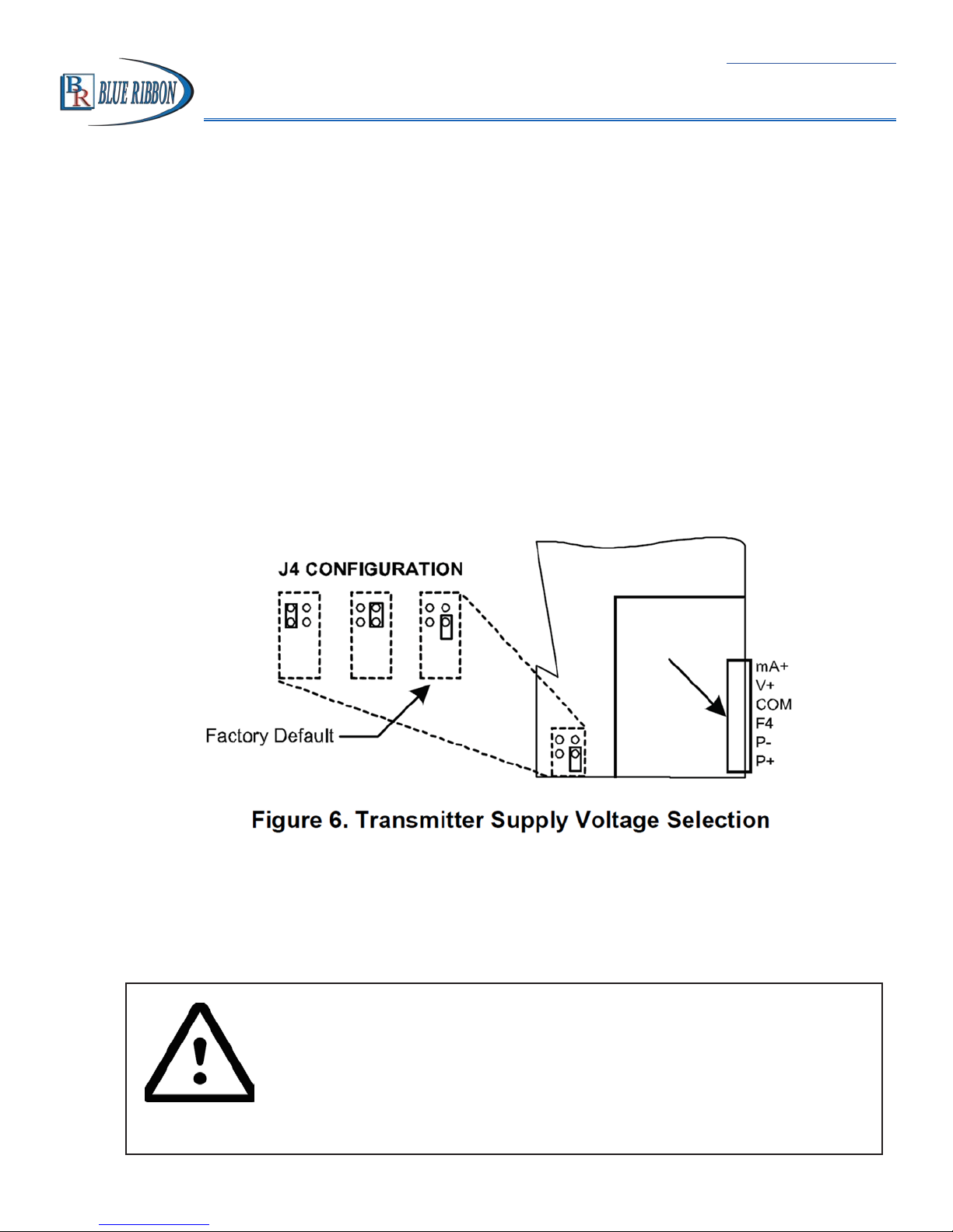
5.4. Transmitter Supply Voltage Selection (P+, P-)
All meters, including models equipped with the 12/24 VDC power option, are shipped from the
factory configured to provided 24 VDC power for the transmitter or sensor.
If the transmitter requires 5 or 10 VDC excitation, the internal jumper J4 must be configured
accordingly.
To access the voltage selection jumper:
1.
Remove all the wiring connectors.
2.
Unscrew the back cover.
3.
Slide out the back cover by about 1 inch.
4.
Configure the J4 jumper, located behind the input signal connector,
for the desired excitation voltage shown.
5.5. Connections
All connections are made to removable screw terminal connectors located at the rear of the
meter.
Use copper wire with 60 °C or 60/75 °C insulation for all line voltage
connections. Observe all safety regulations. Electrical writing should be
performed in accordance with all applicable national, state, and local
codes to prevent damage to the meter and ensure personnel safety.
14
Return to Table of Contents
Model BD300 Analog Input Process Meter Instruction Manual
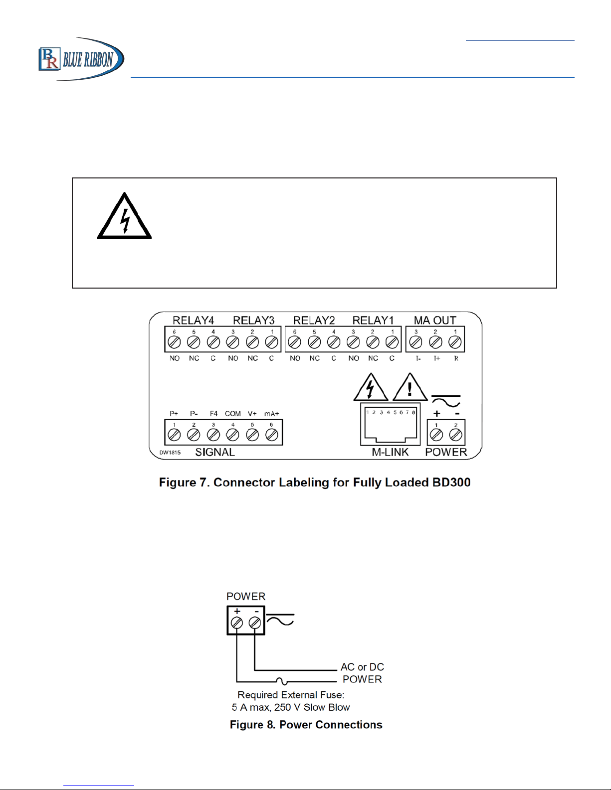
5.6. Connectors Labeling
The connectors’ label, affixed to the meter, shows the location of all connectors available with
requested configuration.
Do not connect any equipment other than Blue Ribbon’s
expansion modules, cables, or meters to the RJ45 M-LINK
connector. Otherwise damage will occur to the equipment
WARNING!
and the meter.
5.7. Power Connections
Power connections are made to a two-terminal connector labeled POWER on Figure 7 on page
19. The meter will operate regardless of DC polarity connection. The + and – symbols are only
a suggested wiring convention.
15
Return to Table of Contents
Model BD300 Analog Input Process Meter Instruction Manual
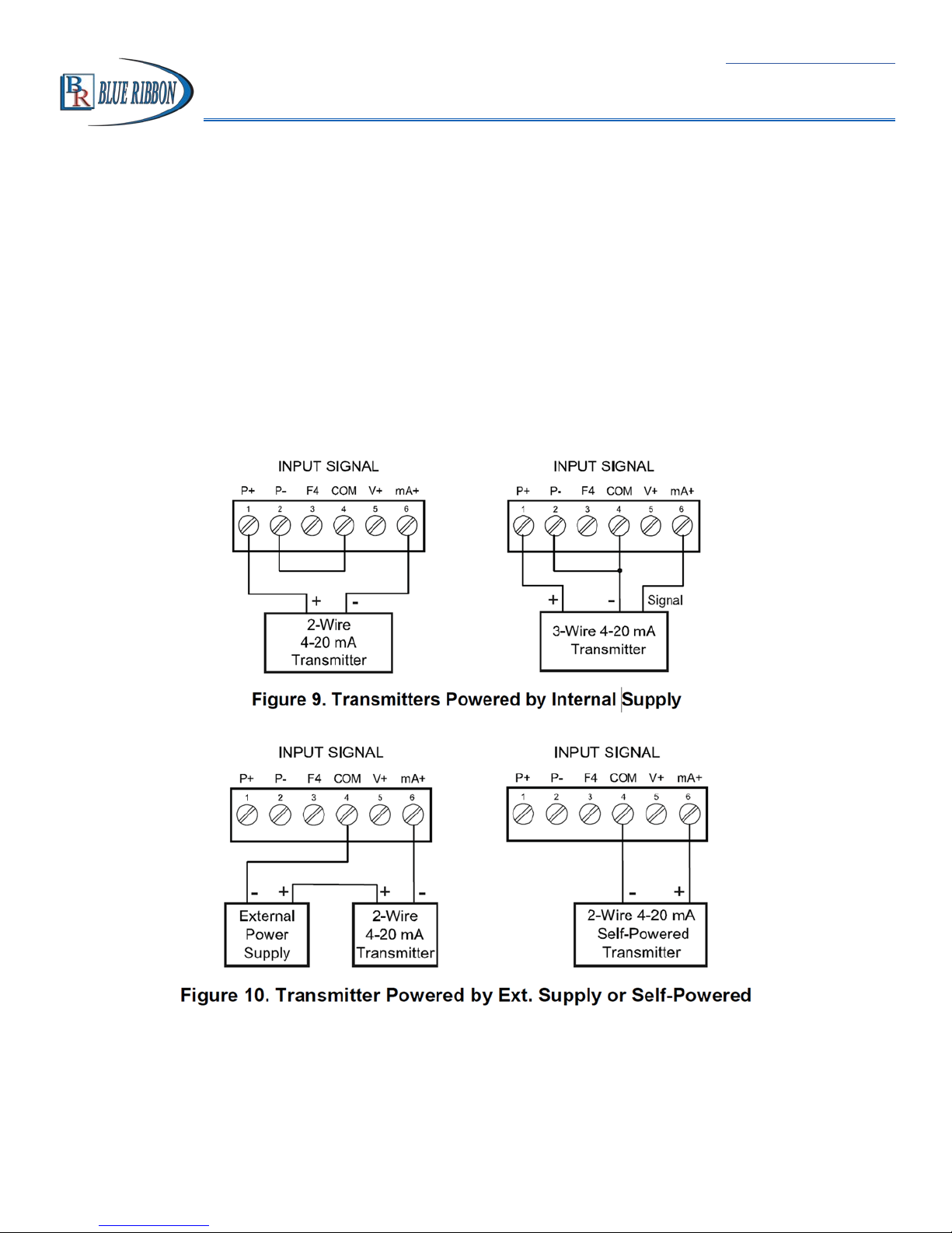
5.8. Signal Connections
Signal connections are made to a six-terminal connector labeled SIGNAL on Figure 7. The COM
(common) terminal is the return for the 4-20 mA and the ±10 V input signals.
5.9. Current and Voltage Connections
The following figures show examples of current and voltage connections.
There are no switches or jumpers to set up for current and voltage inputs. Setup and programming is performed through the front panel buttons.
The current input is protected against current overload by a resettable fuse. The display may or
may not show a fault condition depending on the nature of the overload.
The fuse limits the current to a safe level when it detects a fault condition, and automatically
resets itself when the fault condition is removed.
16
Return to Table of Contents
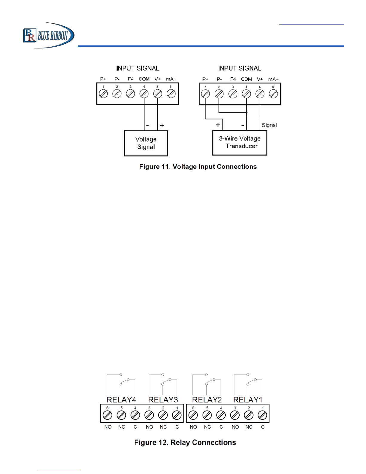
Model BD300 Analog Input Process Meter Instruction Manual
The meter is capable of accepting any voltage from -10 VDC to +10 VDC
5.10. ModBUS RTU Serial Communications
Serial communications connection is made to an RJ45 connector labeled M-LINK on Figure 7.
For interfacing to the BULLDOG, use the BD232SA for RS-232, the BD422SA for RS-485, or the
e.g.
BDUSBSA for the USB. The same port is used for interfacing with all expansion modules (
external relays, digital I/O).
Using the BDCCC meter copy cable for meter-to-meter interfacing for cloning purposes (
i.e.
copying settings from one meter to other meters).
5.11. Relay Connections
Relay connections are made to two six-terminal connectors labeled RELAY1 – RELAY 4 on Figure
7. Each relay’s C terminal is common only to the normally open (NO) and normally closed (NC)
contacts of the corresponding relay. The relays’ C terminals should not be confused with the
COM (common) terminal of the INPUT SIGNAL connector.
17
Return to Table of Contents
Model BD300 Analog Input Process Meter Instruction Manual
5.12. Switching Inductive Loads
The use of suppressors (snubbers) is strongly recommended when switching inductive loads to
prevent disrupting the microprocessor’s operation. The suppressors also prolong the life of the
relay contacts. Suppression can be obtained with resistor-capacitor (RC) networks assembled
by the user or purchased as complete assemblies. Refer to the following circuits for RC network
assembly and installation:
Choose R and C as follows:
R: 0.5 to 1 Ω for each volt across the contacts
C: 0.5 to 1 µF for each amp through closed contracts
Notes:
1.
Use capacitors rated for 250 VAC
2.
RC networks may affect load release time of solenoid loads. Check to confirm proper
operation.
3.
Install the RC network at the meter’s relay screw terminals. An RC network may also
be installed across the load. Experiment for best results.
18
Return to Table of Contents
Model BD300 Analog Input Process Meter Instruction Manual
5.13. RC Networks Available from Blue Ribbon Corp
RC networks are available from Blue Ribbon Corp and should be applied to each relay contact
switching an inductive load. Part number: BD6901.
Note: Relays are de-rated to 1/14th HP (50 watts) with an inductive load.
5.14. F4 Digital Input Connections
A digital input, F4, is standard on the meter. This digital input is connected with a normally open
contact across F4 and COM, or with an active low signal applied to F4.
5.15. 4-20 mA Output Connections
Connections for the 4-20 mA transmitter output are made to the connector terminals labeled
MA OUT. The 4-20 mA output may be powered internally or from an external power supply.
19
Return to Table of Contents
Model BD300 Analog Input Process Meter Instruction Manual
5.16. Analog Output Transmitter Power Supply
The internal 24 VDC power supply powering the analog output may be used to power other
devices, if the analog output is not used. The I+ terminal is the +24 V and the R terminal is the
return.
5.17. External Relays & Digital I/O Connections
The relay and the digital I/O expansion modules BDXM & BDIO are connected to the meter
using a CAT5 cable provided with each module. The two RJ45 connectors on the expansion
modules are identical and interchangeable; they are used to connect additional modules to the
system.
Note: The jumper located between the RJ45 connectors of the BDIO must be removed on the
second digital I/O module in order for the system to recognize it as module #2.
WARNING!
Do not connect ar disconnect the expansion modules with
the power on!
More detailed instructions are provided each optional
expansion module.
20
Return to Table of Contents
Model BD300 Analog Input Process Meter Instruction Manual
5.18. Interlock Relay Feature
As the name implies, the interlock relay feature reassigns one or more alarm/control relays for
use as interlock relay(s). Interlock contact(s) are wired to digital input(s) and trigger the interlock
relay. This feature is enabled by configuring the relay, and relative digital input(s) (see page 61).
In one example, dry interlock contacts are connected in series to one digital input which will be
used to force on (energize) the assigned interlock power relay when all interlock contacts are
closed (safe). The interlock relay front panel LED flashes when locked out. The interlock relay
would be wired in-series with the load (N/O contact). See below.
21

Model BD300 Analog Input Process Meter Instruction Manual
6. Setup and programmIng
The meter is factory calibrated prior to
shipment to read in milliamps and volts
depending on the input selection. The
calibration equipment is certified to NIST
standards.
Overview
Return to Table of Contents
There are no jumpers to set for the meter input selection. Setup and programming is done
through the front panel buttons. After power and input signal connections have been completed
and verified, apply power to the meter.
22
Model BD300 Analog Input Process Meter Instruction Manual
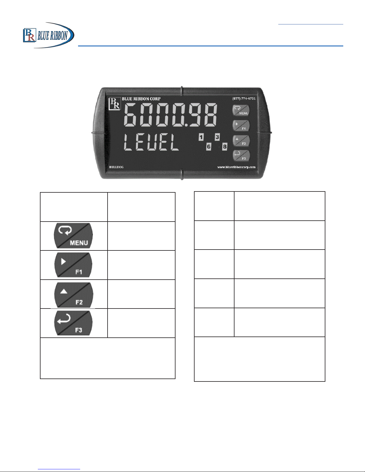
6.1. Front Panel Buttons and Status LED Indicators
Return to Table of Contents
Button
Description
Symbol
Menu
Right Arrow/F1
Up Arrow/F2
Enter/F3
Note:
F4 is a digital input. Alarms 5-8
are enabled when relay expansion
module is installed.
LED Status
1-8 Alarm 1-8 Indicator
Flashing: Relay in
1-8 M
manual control mode
T Flashing: Tare
Flashing: Relay
1-8
interlock switch open
Note:
LEDs for relays in manual mode flash
with the “M” LED every 10 seconds.
“M” flashing by intself indicates Aout -
manual control is used.
23

Return to Table of Contents
Model BD300 Analog Input Process Meter Instruction Manual
• Press the Menu button to enter or exit the Programming Mode at any time.
• Press the Right arrow button to move to the next digit during digit or decimal point
programming.
• Press or hold the Up arrow button to scroll through the menus, decimal point, or to
increment the value of a digit.
• Press the Enter button to access a menu or to accept a setting.
• Press and hold the Menu button for three seconds to access the advanced features of
the meter.
6.2. Display Functions & Messages
The meter displays various functions and messages during setup, programming, and operation.
The following table shows the main menu functions and messages in the order they appear in
the menu.
Display Parameter Action/Setting Description
SEtuP
InPut
mA
UoLt
d-SCAL
units
dEc Pt
PU 1
PU 2
ProG
Setup
Input
4-20 mA
0-10 VDC
Dual-scale
Units
Decimal Point
PV1
PV2
Program
Enter
Setup
menu
Enter
Input
selection menu
Set meter for 4-20 mA Input
Set meter for ±10 VDC input
Press Enter to select dual-scale display for
some level applications (Select Yes or No)
Select the display units/tags
Set decimal point
PV1 decimal point (Level)
PV2 decimal point (Level)
Enter the
Program
menu
SCALE
SCAL 1
SCAL 2
Scale
Scale 1
Scale 2
Enter the
Enter the
Enter the
24
Scale
menu
Scale
Menu for PV1
Scale
menue for PV2

Model BD300 Analog Input Process Meter Instruction Manual
Display Parameter Action/Setting Description
Return to Table of Contents
CAL
InP 1
di5 1
InP 2
dis 2
Error
dSPLAy
biG
LittlE
d-Inty
rELAY
Calibrate
Input 1
Display 1
Input 2
Display 2
Error
Display
Big Display
Little Display
Display Intensity
Relay
Enter the
Calibrate input 1 signal or program input
1 value
Program display 1 value
Calibrate input 2 signal or program input 2
value (up to 32 points)
Program display 2 value (up to 32 points)
Error, calibration not successful, check sig-
nal or programmed value
Enter the
Press Enter to assign the Main display pa-
rameter (default: PV)
Press Enter to assign the small display pa-
rameter (default: engineering units)
Set display intensity level from 1 to 8
Enter the
Calibration
Display
Relay
menu
menu
menu
rLy 1
Act 1
Auto
A-mAn
LAtCH
Lt-Clr
AltErn
SamPL
OFF
SEt 1
Relay 1
Action 1
Automatic
Auto-manual
Latching
Latching-cleared
Alternate
Sampling
Off
Set 1
Relay 1 setup
Set relay 1 action
Set relay for automatic reset
Set relay for automatic & manual reset any
time
Set relay for latching operation
Set relay for latching operation with man-
ual reset only after alarm condition has
cleared
Set relay for pump alternation control
Set relay for sampling operation
Disable relay and front panel status LED
(Select Off to enable Interlock feature)
Program set point 1
25
 Loading...